
This is an attempt to collect all known and available modifications for Philips CD-i players in a single article. Consider it a work in progress – I will add new information from time to time. Please give feedback if you find an error or want to add something to this article.
Due to the plethora of different models, versions and revisions of CD-i players that have been sold under the Philips / Magnavox or entirely different brands (OEM), it is virtually impossible to create one big list that contains every player. I chose a different approach with several lists to cover most of the hardware combinations: Available modifications, mainboards, and video encoders.
Available modifications
This is an overview of the available modifications:
- 50/60 Hz modification: This is done by changing the STAND! / STANDIN! signal to make the player believe that it is from a different region (PAL = 0 and NTSC = 1). It does not really change a PAL player to NTSC or vice versa, but it changes the refresh rate of the video output.
- PAL/NTSC modification: This is the actual hardware change from PAL to NTSC. Depending on mainboard and video encoder, this can be as easy as installing a DFO or as hard as populating the entire analog video section of the mainboard or encoder panel.
- RGB modification: This will add an RGB video output to your CD-i player. Useful for all CD-i players from the NTSC regions and the cheaper players from the PAL regions.
- NVRAM modification: Depending on mainboard and ROM, the 8 KB Timekeeper chip of some players can be upgraded to a 32 KB SRAM chip in a SmartWatch socket.
- CDM: Information about the CD loading mechanism that can be connected to the mainboard and is usually found in the players.
- PSU: Information about the power supply unit.
- Adapters and cables: Various cables from Philips, adapters for connecting accessories of other computer or game systems to CD-i players and replacement power supplies/adapters.
- ROM/Software modifications: Add missing features and customise the player shell.
Mainboards
The focus of this list lies on the 50/60 Hz modification. Players without SCART connector/RGB video output will need additional modifications, as explained in the video encoders section.
Before proceeding, identify the mainboard with the aid of the model and version of your CD-i player. It is important to understand the versioning that Philips uses. The comparision tables and explanations at ICDIA are vital for this understanding.
To help identifying the mainboard, this list also includes the major CD-i player versions. CD-i players from other regions and brands are only listed if they have a different model number or other special features. And as a rule of thumb, US players always have 17 added to the major version/revision (i.e. /17 /37 /57 /77 /97).
- JNMS, Maxi MMC and Mini MMC (prof.)
- Mini MMC (NTSC)
- Mini MMC
- Mini MMC-based
- Mono I
- Mono II
- Mono III
- Mono III-based
- Roboco (Mono III-based)
- Mono IV (large players)
- Mono IV (small players)
- Mono IV (B&O)
Other mainboards: - GoldStar / LG (midi-size players)
- GoldStar / LG (portable players)
- Kyocera
- Sony PU-4
- Sony PU-702
JNMS, Maxi MMC and Mini MMC (prof.)
For the sake of completeness, these are the mainboards of the early professional and authoring players:
- 181 Multi Media Controller module – the first professional player with JNMS mainboard (together with the 180 CD-i Player module). With the 182 System Expansion module, it became the first authoring player.
- 601 and 602 – professional players with Maxi MMC mainboard.
- 604 – professional player with Mini MMC mainboard.
- 605 and 605T – authoring players with Mini MMC mainboard.
Not much is known about the first two; the following list is almost exclusively about Mini MMC (prof.):
- Service manual: Here (use CDI 220/00 service manual); there is some technical documentation as well, also for some of the other players.
- Video encoder: CXA1145P.
- NVRAM: 8 KB only.
- CDM: Philips CDM 9/44.
- PSU: Further details will follow.
- 50/60 Hz modification: Not needed; players come with pre-installed multi-region switches.
Professional and authoring players have multi-region encoder panels.
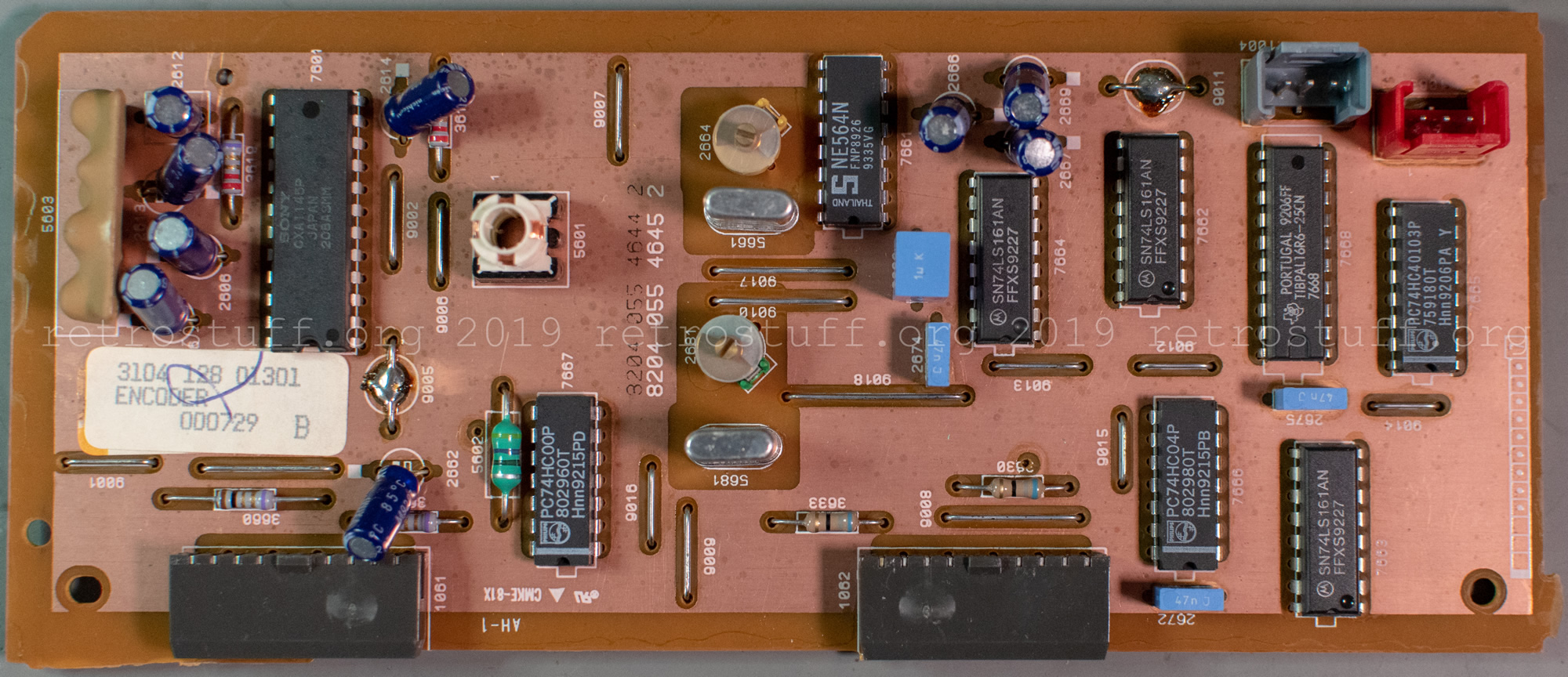
Mini MMC (NTSC)
Found in the 205/11 (Japan), 205/17T (Memorex CDI 2200) and 910/17P (US) consumer players:
- Service manual: Here (CDI 220/00) and here (CDI910 Technical Training Manual).
- Video encoder: CXA1145P.
- NVRAM: 8 KB only.
- CDM: Philips CDM 9/44.
- PSU: Further details will follow.
- 50/60 Hz modification: Possible, but not yet documented. The following information has been compiled together with CD-i Fan and is considered untested.
Location: Underneath the SLAVE microprocessor on the SMD/track side. A 1 kΩ resistor sets the STAND! signal.
3247 to GND = PAL / 3246 to +5V = NTSC.
Do not set these resistors on the other two Mini MMC variants (see above and below)!
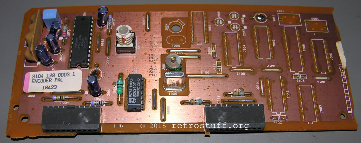
- PAL/NTSC modification: Probably possible, but needs some additional components or swapping the encoder panels.
Encoder panels are available as PAL or NTSC versions for consumer players.
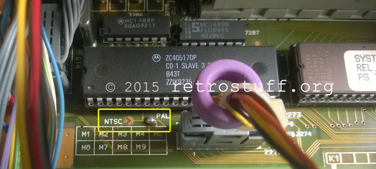
Mini MMC
Found in the 205/00 and 220/00 consumer players:
- Service manual: Here (CDI 220/00) and here (CDI910 Technical Training Manual).
- Video encoder: CXA1145P.
- NVRAM: 8 KB only.
- CDM: Philips CDM 9/44.
- PSU: Further details will follow.
- 50/60 Hz modification: Possible and documented here.
Move the solder blob in the lower left of the Mini MMC panel to PAL or NTSC for a permanent modification or add a switch. (Do not attempt this modification on professional players!)
- PAL/NTSC modification: Probably possible, but needs some additional components or swapping the encoder panels.
Encoder panels are available as PAL or NTSC versions for consumer players.
Mini MMC-based
Found in the 310, 350 and 360 portable players:
- Service manual: Here.
- Video encoder: CXA1145M.
- NVRAM: 8 KB only.
- CDM: Philips CDM 9/44.
- PSU: Further details will follow.
- 50/60 Hz modification: Not needed; players come with pre-installed multi-region switches.
Mono I
Found in the 210/00, 220/20 and 200/17 (US) consumer players:
- Service manual: Here.
- Video encoder: CXA1145P.
- NVRAM: 8 KB “SGS-Thomson” only, set by 0 Ω resistor 3201.
(The service manual reveals two “NOT IMPLEMENTED” resistors 3205 and 3227 for a “Motorola” chip. These match the 32 KB resistors of the Mono II board.) - CDM: Philips CDM 9/44.
- PSU: Further details will follow.
- 50/60 Hz modification: Possible and documented here.
Location: Grid square C6 on the SMD/track side. A 1 kΩ resistor (1% / 0,1 W) sets the STAND! signal.
3243 to GND = PAL / 3246 to +5V = NTSC.
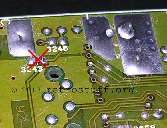
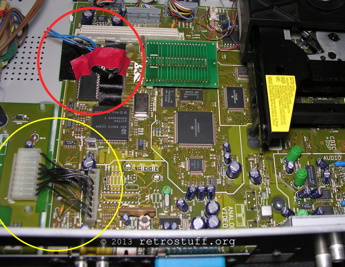
- PAL/NTSC modification: Probably possible, but needs some additional components. See the unpopulated area of this CDI220/20 next to the yellow circle:
Mono II
Found in the 210/20, 220/40 and 200/37 (US) consumer players:
- Service manual: Here.
- Video encoder: CXA1145P.
- NVRAM: 8 KB “SGS-Thomson”, set by 0 Ω resistor 3201.
32 KB “DALLAS”, set by 0 Ω resistors 3205 and 3227. - CDM: Philips CDM 9/44.
- PSU: Further details will follow.
- 50/60 Hz modification: Possible, but not yet documented. It is basically the same as for Mono I.
Location: Grid square D2 on the SMD/track side. A 1 kΩ resistor (2% / 0,25 W) sets the STANDIN! signal.
3243 to GND = PAL / 3246 to +5V = NTSC. - PAL/NTSC modification: Probably possible, but needs some additional components, see Mono I.
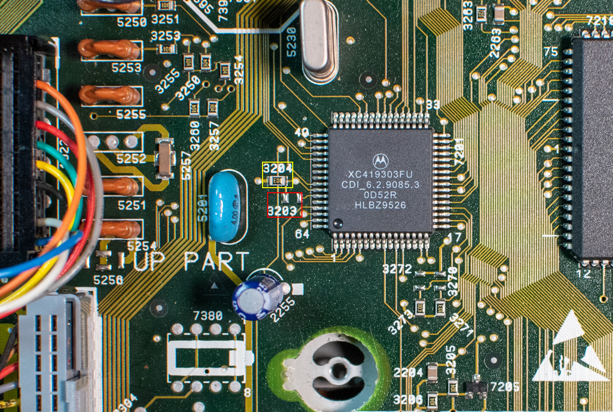
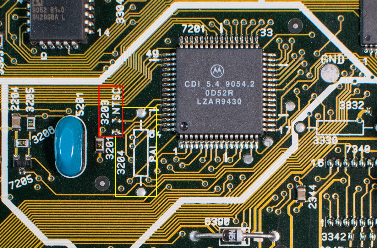
Mono III
Found in the 210/40 and 220/60 consumer players, as well as in the 21TCDI30 TV:
- Service manual: Here.
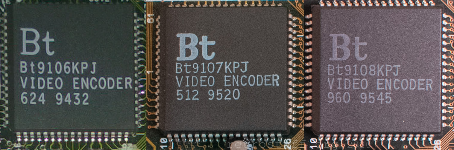
- Video encoder: BT9106KPJ (Calvin).
- NVRAM: 8 KB, set by 4,7 kΩ resistor 3241.
32 KB, set by 0 Ω resistors 3244 and 3246. - CDM: Philips CDM 12.4.
- PSU: 20PS302.
- 50/60 Hz modification: Possible and documented here.
Location: Grid square D2 on the component side. A 10 kΩ resistor (1% / 0,1 W) sets the STANDIN! signal.
3204 to GND = PAL / 3203 to +5V = NTSC.
- PAL/NTSC modification: Installing a DFO is the next logical step.
Mono III-based
Found in the FW380i mini system:
- Service manual: Here.
- Video encoder: BT9106KPJ (Calvin) / BT9107KPJ (Hobbes).
- NVRAM: 8 KB only, set by 4,7 kΩ resistor 3241.
- CDM: Philips CDM 12.1.
- PSU: 20PS303.
- 50/60 Hz modification: Pointless, unless you combine it with an RGB and/or a PAL/NTSC modification. See the video encoders section.
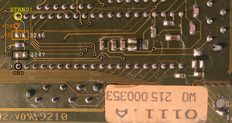
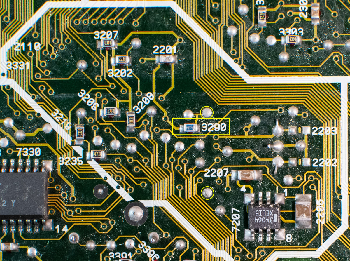
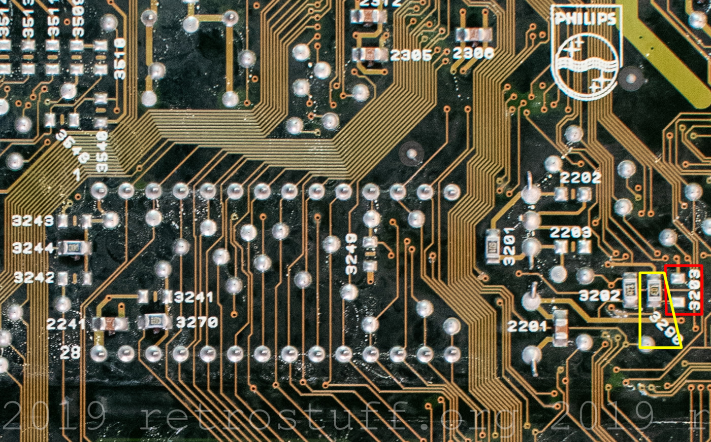
Roboco (Mono III-based)
Found in all top-loading consumer players (450, 550, 5000, 9000, GDI-750 and GDI-1000):
- Service manual: Here.
- Video encoder: BT9106KPJ (Calvin).
- NVRAM: 8 KB only, set by 4,7 kΩ resistor 3241.
Upgrade to 32 KB NVRAM. - CDM: Philips CDM 12.1T.
Philips CDM 12.1T Laser Sledge Replacement. - PSU: 20PS301 (22ER9156).
- 50/60 Hz modification: Pointless, unless you combine it with an RGB and/or a PAL/NTSC modification. See the video encoders section.
Location: The bird-shaped area in the center of the mainboard, both sides. The information in the service manual about which resistor sets the STANDIN! signal is partially wrong/misleading!
3204 (component side) or 3290 (track side) to GND (0 Ω) = PAL.
3203 (component side) to +5V (10 kΩ / 5% / 0,1 W) = NTSC.
- ROM/Software modifications: See below.
Mono IV (large players)
Found in the 210/60, 220/80 and 740 consumer players, as well as in the 615, 660 and 670 professional players:
- Service manual: Here.
- Video encoder: BT9106KPJ (Calvin) / BT9108KPJ (Hobbes).
- NVRAM: 8 KB, set by 4,7 kΩ resistor 3241.
32 KB, set by 0 Ω resistors 3244 and 3270. - CDM: Philips CDM 12.1, VAM1201 or VAM1202.
(Also: optional CDM 12.4 footprint in the service manual.) - PSU: 20PS306 or 20PS308 (consumer) and 20PS307 (professional).
- 50/60 Hz modification: Possible and documented here.
Location: Grid square C2 on the SMD/track side. A 10 kΩ resistor (5%) sets the STANDIN! signal.
3290 to GND = PAL / 3203 to +5V = NTSC.
- PAL/NTSC modification: Installing a DFO is the next logical step.
- ROM/Software modifications: See below.
Mono IV (small players)
Found in all 470 and 490 consumer players:
- Service manual: Here.
- Video encoder: BT9107KPJ / BT9108KPJ (Hobbes).
- NVRAM: Same as above.
Upgrade to 32 KB NVRAM. - CDM: Philips CDM 12.1.
(Also: optional CDM 12.4 footprint in the service manual.) - PSU: 20PS304.
- 50/60 Hz modification: Pointless, unless you combine it with an RGB and/or a PAL/NTSC modification. See the video encoders section.
- ROM/Software modifications: See below.
Mono IV (B&O)
Found in the Bang & Olufsen BeoCenter AV5:
- Service manual: N/A. (Partially featured in the 210/60, 220/80 and 470 service manuals.)
- Video encoder: BT9107KPJ (Hobbes).
- NVRAM: 32 KB only. (See above.)
- CDM: Philips CDM 12.5 or VAM1205 (CDM 12.4 / VAM1204 with brushless motor).
- PSU: Further details will follow.
- 50/60 Hz modification: Not needed; video format is set by the TV.
Other mainboards
GoldStar / LG (midi-size players)
Not much is known about the GoldStar / LG boards. The earlier designations Motorola 68341 Integrated CD-i Engine and Portable CD-i Board (PCDI) have turned out to be wrong: These boards have a Motorola MC 68340 Integrated Processor with DMA.
Found in the GDI-700M, GDI-S710, DVS VE-200 and Knowlogy K2000-MSS midi-size players:
- Service manual: N/A.
- Video encoder: BT9107KPJ (Hobbes).
- NVRAM: 32 KB only.
- CDM: Sony KSM-2101ADM / KSS-210A.
- PSU: Further details will follow.
- 50/60 Hz modification: Not needed; players come with pre-installed multi-region switches (except GDI-S710).
GoldStar / LG (portable players)
Found in the 370, GPI-1100M, GPI-1200M and NBS Lookman ID portable players:
- Service manual: N/A. (See above.)
- Video encoder: AD722 RGB to NTSC/PAL Encoder.
- NVRAM: 32 KB only.
- CDM: Sanyo SF-92.5 with 4/12 pins.
- PSU: Further details will follow.
- 50/60 Hz modification: Not needed; players come with pre-installed multi-region switches.
Kyocera
Found in the PRO 1000S portable player:
- Service manual: N/A.
- Video encoder: CXA1645M.
- NVRAM: 8 KB only.
- CDM: KSS-320B.
- PSU: Further details will follow.
- 50/60 Hz modification: Unknown.
Sony PU-4
Found in the IVO-V10 and IVO-V11 portable players:
- Service manual: Here.
- Video encoder: CXA1145M.
- NVRAM: 8 KB only.
- CDM: KSM-311AAM / KSS-311A.
- PSU: Further details will follow.
- 50/60 Hz modification: Unknown.
Sony PU-702
Found in the IVO-N7 portable player:
- Service manual: Here.
- Video encoder: CXA1145M.
- NVRAM: 8 KB only.
- CDM: KSM-311AAM / KSS-311A.
- PSU: Further details will follow.
- 50/60 Hz modification: Unknown.
Video encoders
Let’s have a look at the prerequisites and additional possibilities for your CD-i player, based on the video encoder family:
Sony CXA1145P/M
- Datasheet: Here.
- RGB modification: Here, here and here.
Professional CD-i players have a DE-9 RGB port. Schematics for a SCART adapter can be found here. If you have a consumer Mini MMC player then you might want to look into this possibility as well.
Portable CD-i players have a proprietary RGB port. An adapter hasn’t been made yet. - PAL/NTSC modification: A DFO for the system clock is possible, but that won’t change the colour subcarrier frequency. Consider adding missing components according to the service manual. NTSC uses many more components than PAL. (i.e. modification of NTSC players is easier than of PAL players.)
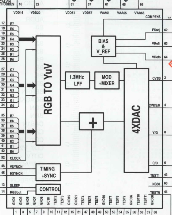
Brooktree BT9106 & BT9107 / BT9108 (Calvin & Hobbes)
- Datasheet: N/A.
- RGB modification: RGB SCART modification for 470 and 490 – is valid for all Mono IV players without RGB.
For Roboco players and/or if SCART is not needed, there are other solutions by Mobius Strip Technologies (GitHub) and 8Bitplus. - PAL/NTSC modification: A DFO for the system clock is possible and recommended.
NVRAM
Moved completey reworked version of the NVRAM section to a new article.
Adapters and cables
Cables and adapters designed by Philips
- Many serial cables are listed on the PMpro mirror on ICDIA.
- A 22ER9208 I/O Port splitter is needed for some CD-i players to play certain games with two players simultaneously or connect a keyboard and/or modem. The world of CD-i has a project to replicate this port-splitter.
- With a null-modem cable you can access and transfer data in the NVRAM. For example, with CD-i Link (cdilink) or CD-interlink and a terminal.
Adapters for connecting accessories of other computer or game systems to CD-i players
USB
- With the Arduino CD-i Controller Library by TwBurn you can connect USB controllers, mice and keyboards to CD-i players. Several code examples are available and most of them make use of a USB Host Shield.
- There is also a USB-2-CDI adapter that can be pre-ordered on controlleradapter.com.
Bluetooth
- The CD-i Bluetooth controller module is a plug & play solution to connect Bluetooth controllers to CD-i players. Also on GitHub.
- The BlueRetro Multiplayer Bluetooth controllers adapter supports CD-i since v0.15. More information here.
Super Nintendo / Super Famicom
- With the Arduino-based SNEStoCDi adapter by Laurent Berta you can connect Super Nintendo (SNES) / Super Famicom (SFC) gamepads to CD-i players.
- This is a fork of the SNEStoCDi project by Larry Erb. It contains layout and code changes for Arduino Nano and ATtiny85.
Mega Drive / Genesis
- GenesisToCDi is an adaptation of SNEStoCDi by UrQuan3 to connect Sega Mega Drive game pads to CD-i players.
- There is also closed-source Arduino-based SMDtoCDI adapter by Lauraiss.
- Technically not an adapter, but it can be converted into one: Philips CD-i RC6 Remote Control Hack.
PlayStation
- With psx2cdi by danhans42 you can connect PlayStation pads to CD-i players. At the moment, it supports digital buttons only.
PC game port
- With the CD-i Gamepad Adapter by Paul Hackmann you can connect analogue PC joysticks and gamepads to CD-i players. The adapter is not available anymore and the website is long gone, but this capture of the website contains an archive with the specifications of the adapter.
PS/2 mouse
- With the Arduino-based PS/2 Mouse to Cdi adapter by Dan Brakeley you can connect PS/2 mice to CD-i players.
Replacement power supplies / adapters
CDI450 and other Roboco CD-i players
All information is now in the new article Philips CD-i Power Supply Units.
CDI370 and other portable GoldStar / LG players
These CD-i players have a Mini-Din-5 socket for the power supply. What makes them special is that they need two voltages (21 V / 1,7 A and 5 V).
- The pinout can be found on retrovideogames.de and allows you to build an adapter with two power supplies.
- As an alternative solution, it was suggested in the Philips CD-i Appreciation Facebook Group to remove the battery and connect an 18 V power supply directly to the terminals on the back (+ to the upper left terminal and – to the lower left terminal).
- Another solution has been invented on the Philips CD-i Community Discord server:
Connect a USB-C/USB-A dual port charger (65 W or more) to a Mini-DIN-5 plug according to the pinout. +5 V from the USB-A output and +20 V from the USB-C output (set to 20 V with an additional USB-PD trigger module).
ROM/Software modifications
Simple and not so simple modifications that could render your CD-i player useless.
Remedy: Use the original ROM and/or delete the NVRAM to go back to normal.
- A modification of a ROM file has been attempted here for the first time. Even though the results were not successful, the article will give you an overview of how to patch a file and how to calculate the required checksums.
- Add the missing Service Shell for CDI660 by patching the DVC ROM. Lots of additional information about modules, headers and checksums.
- Custom ROM for CDI450 (and 550) to make 32 KB NVRAM upgrades possible.
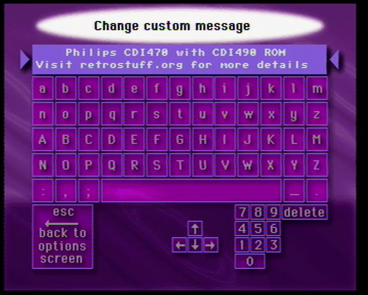
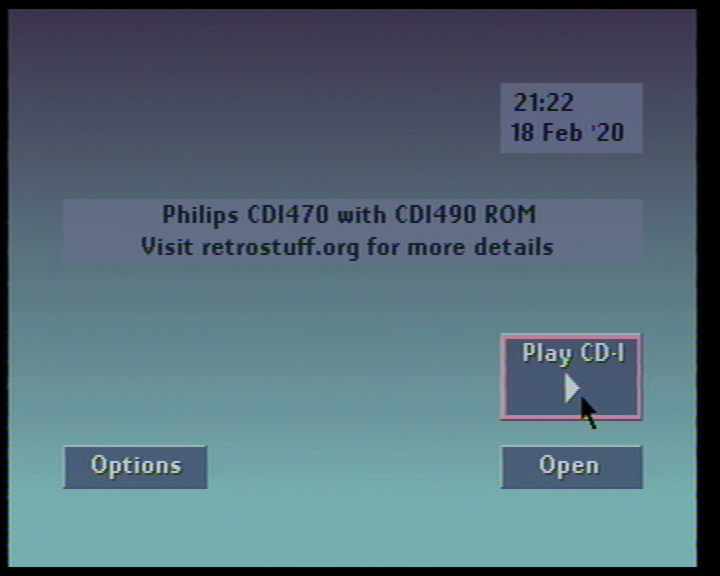
- Customise the startup message of CDI660, 670 and even 490 players with the CDI 660/670 Key disc and PIN code 3094.
This customization is not limited to the aforementioned models and could work on other Mono IV based CD-i players as well – if the ROM supports it.
Hint: Use a keyboard to enter the text. CDI490 requires a 22ER9208 I/O Port splitter for the keyboard to work.
If you don’t want to use the key disc, you can simply create a text file with your message on a PC and name it “.keycontrol” (without the quotes). You can even use special characters like “/” that are not possible with the editor of the key disc. Then, place the file in the NVRAM, e.g. by downloading it to /nvr with the CD-i Link program and restart the CD-i player.
Changelog
2020-01-13: Added pictures and schematic of the Bt video encoder.
2020-01-17: Added more details to the 50/60 Hz modifications and links to the service manuals.2020-01-29: Added the NVRAM section.
2020-02-18: Added the ROM/Software section.
2020-04-24: Added the Adapters and cables section.
2020-08-30: Moved FW380i to Mono III-based and added link to the service manual.2020-10-01: Added more information to the 32 KB NVRAM section.
2020-10-02: Added RGB modifications for the Bt video encoder.
2020-11-16: Split Mono IV section into three separate sections.
2021-01-08: Added the CD-i Controller Library to the Adapters and cables section.
2021-02-06: Moved the 21TCDI30 TV to Mono III.2021-08-24: Added GW-48T08-1 and GW-1244-1 to the NVRAM section.
2021-08-29: Added 32 KB NVRAM upgrade to Roboco and NVRAM section.
2021-12-31: Moved completey reworked version of the NVRAM section to a new article.
2022-01-02: Added information about CDM. More ROM modifications. Minor fixes.
2022-01-07: Added professional, authoring and portable player mainboards. Added Roboco 50/60 Hz mod and pictures. Minor fixes.
2022-01-26: CDI602 confirmed to have Maxi MMC mainboard.
2022-07-20: Added PCDI mainboard sections. Added Bluetooth adapters to the Adapters and cables section.
2022-11-30: Added Replacement power supplies / adapters (Roboco and PCDI-portable) to the Adapters and cables section.
2023-02-02: Tidied up Adapters for connecting accessories… and added GenesisToCDi and psx2cdi to the Adapters and cables section.
2023-04-05: Updated CDM information for all mainboards. Added USB-2-CDI to the Adapters and cables section.
2023-05-28: Renamed PCDI to GoldStar / LG and updated the information.
2023-06-09: Added Kyocera and Sony mainboard sections.
2024-02-18: Added Mini MMC (NTSC) mainboard. Added VAM1205 to Mono IV (B&O). Added another portable GoldStar / LG PSU solution.
2024-09-29: Added information about power supply units. Moved Replacement power supplies / adapters (Roboco) to a new article. Added VAM1201 to Mono IV (large players).
Hi,
I’m really a fan of the cd-i (own two of them).
I see a lot of mods of which I didn’t know until now.
I was wondering if there has been an attempt to connect a hd on the cd-i? Or maybe is trying to?
Love your site.
Regards,
Aad
Many thanks for the feedback! By HD do you mean a hard drive? This is indeed possible with special (authoring) CD-I players, see https://retrostuff.org/2019/07/21/first-steps-in-os-9-on-philips-cdi605t/.
Hi,
Fan of your work here!
I was wondering if you can author with the CD-I 615, that is run MediaMogul, for instance ?
Regards,
Raymond
Thanks!
No, unfortunately that’s not possible. 615 is only a professional player and not an authoring player, and lacks many of the necessary features (e.g. additional memory, SCSI and digital connections). Even if you somehow manage to start the MediaMogul disc and script something (think of it as a tool like Macromedia Director), you won’t have any space for the assets and storage. The FDD is simply not enough here.