
My Philips CDI605T/20 needed repairs before I could use it fully. Some of the repairs were mandatory for operation (Timekeeper), while others were to make it easier on the ears (fan, optical disc drive tray). I already had experience with a Mini MMC chassis on the very similar consumer player CDI220/00 and knew what to expect inside (its service manual helped a bit). It is actually possible to perform these repairs without taking the entire case apart (see the Shortcut sections). I took special precautions and took photos of each step so that I could put everything back together in the end.
I began with removing the case and the bezels of the extension cards on the rear. Make sure to slide out the lower card first, otherwise its metal plate will grind on the solder side of the upper card.

Next, I removed the rear panel. There is some weird white-greenish debris on it that I cannot wipe off, probably caused by improper storage in a wet basement. Luckily, there is as good as no rust on the metal parts. I’ve found only very tiny spots on some of the port shieldings. Maybe I will take the whole case apart someday, to give it a proper sanding.
The debris is also present on the right side.

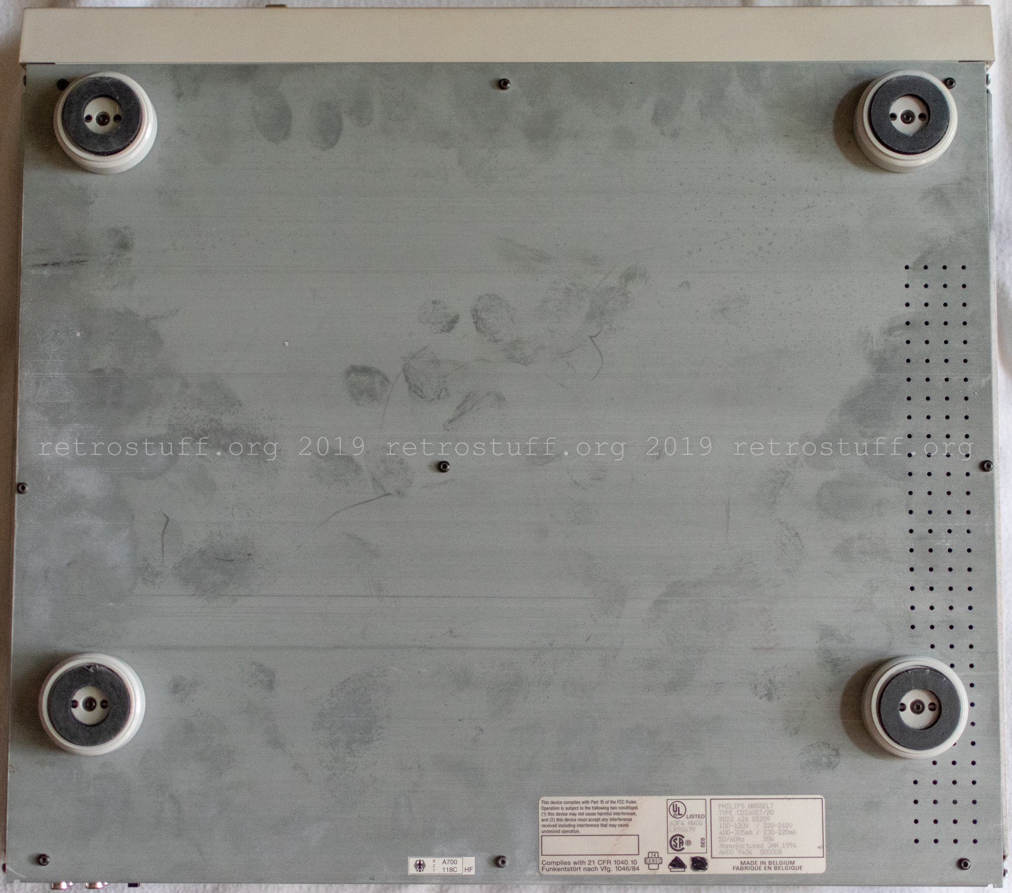
The bottom has collected many fingerprints over the years.
Shortcut: Timekeeper
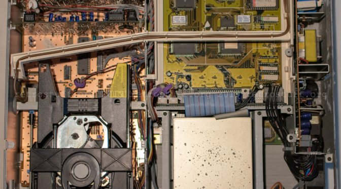
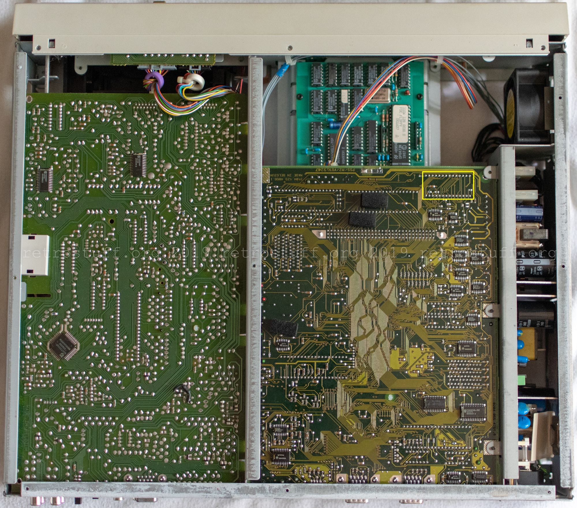
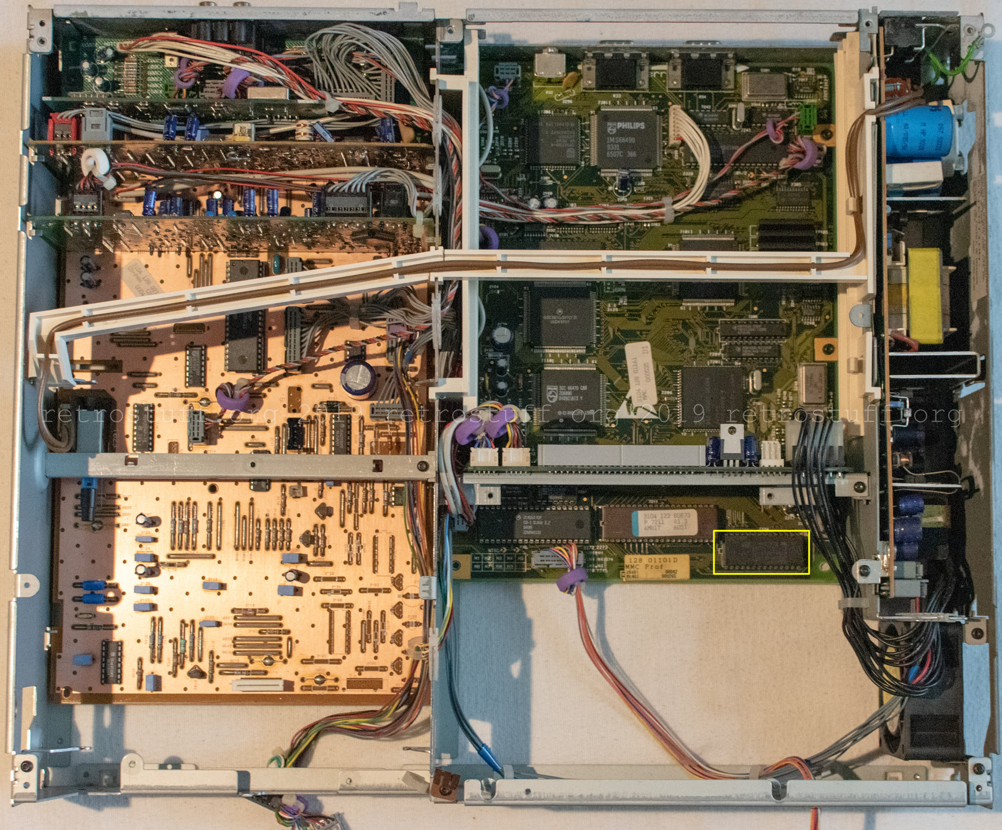
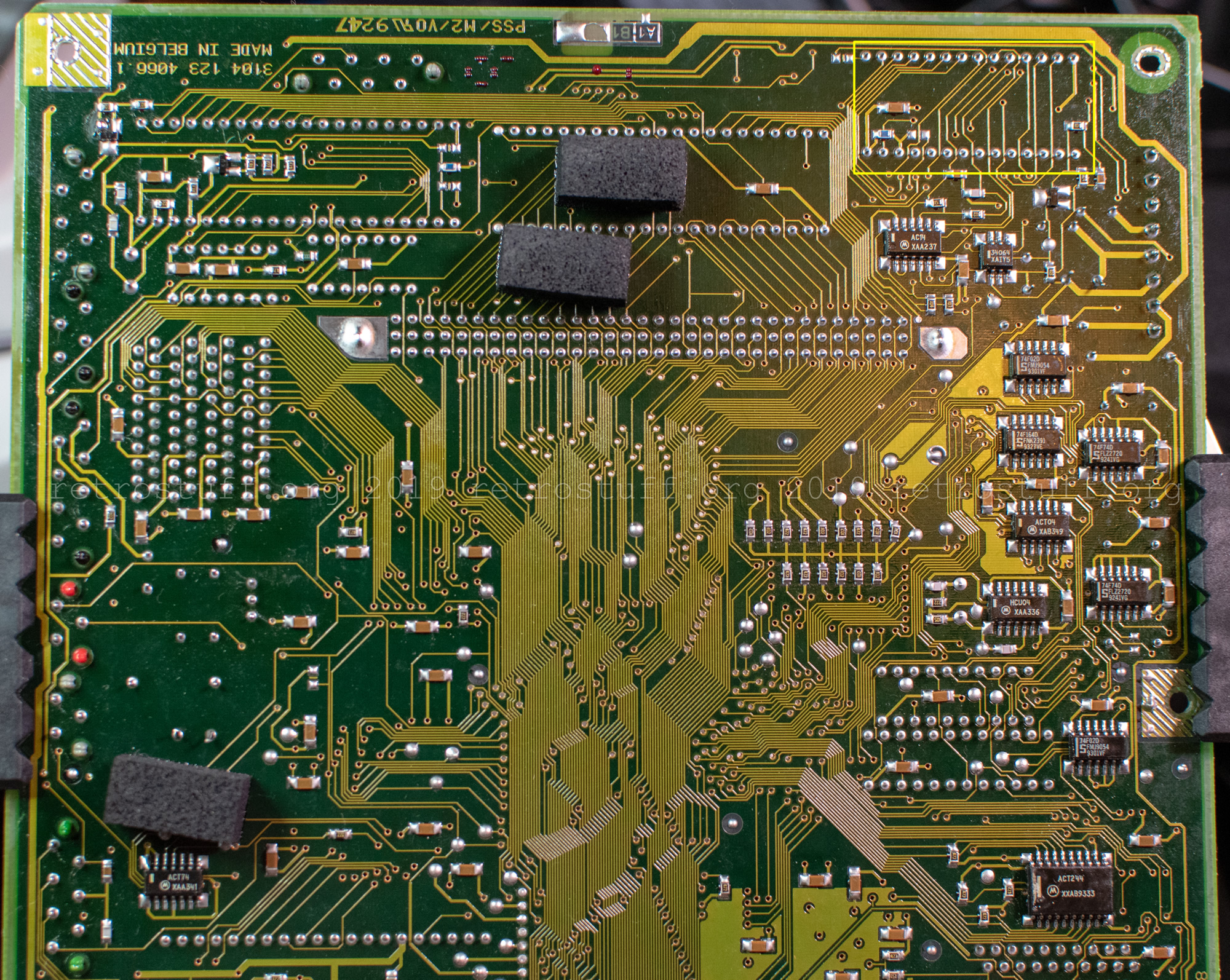
This is a shortcut to access the Timekeeper chip (yellow rectangle). If you remove the floppy disk drive as well, you can access it from here and try to desolder it. I strongly advise against it though, as it is soldered from both sides. Even with a powerful desoldering gun, you won’t be able to do it alone, and the bulky case gets in the way. (Scroll down to the Timekeeper replacement section to see the regular way.)
Optical disc drive maintenance
Philips CD-i players with a tray-loading mechanism have some common failures: The rubber belt gets loose and the grease of the tray mechanism dries over time. This causes the tray not to move at all or to get stuck and/or to make an annoying screaming noise whenever it is opened and closed.
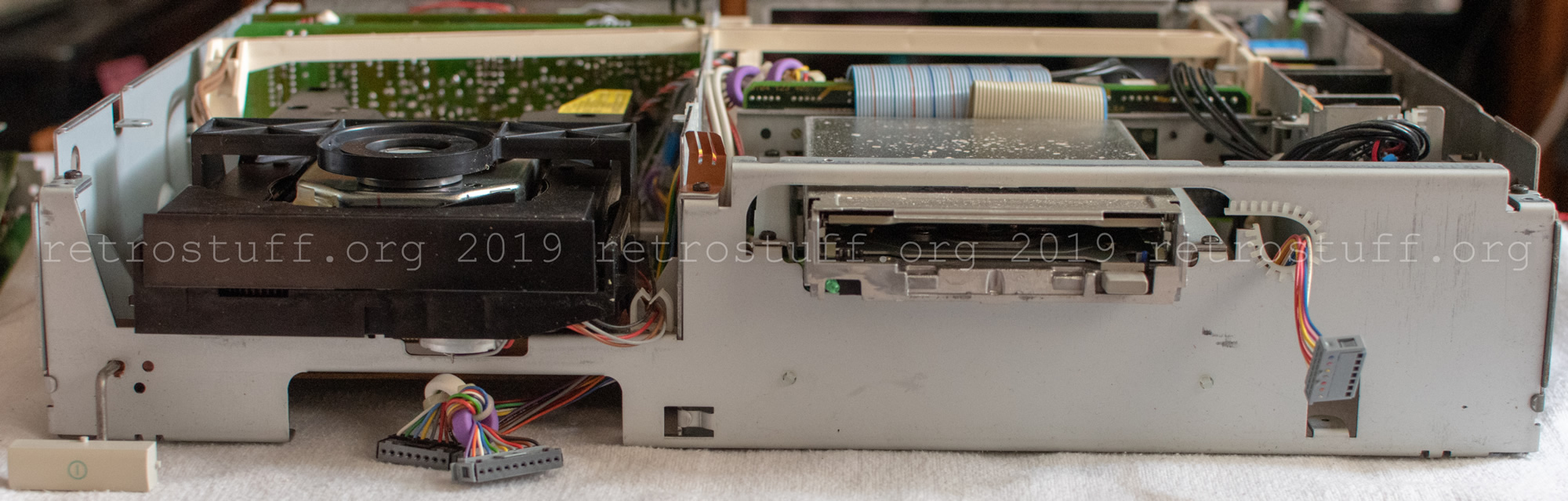
In order to have full access to the optical disc drive (ODD) and document everything, I removed both the bezel and the front panel. While it is possible to remove the ODD with the front panel in place, it will be more difficult to put it back in because of the tight space. However, this is only a matter of experience with this chassis and is not strictly necessary. Regardless of your approach, it is highly recommended that you remove the tray first (see the shortcut below).
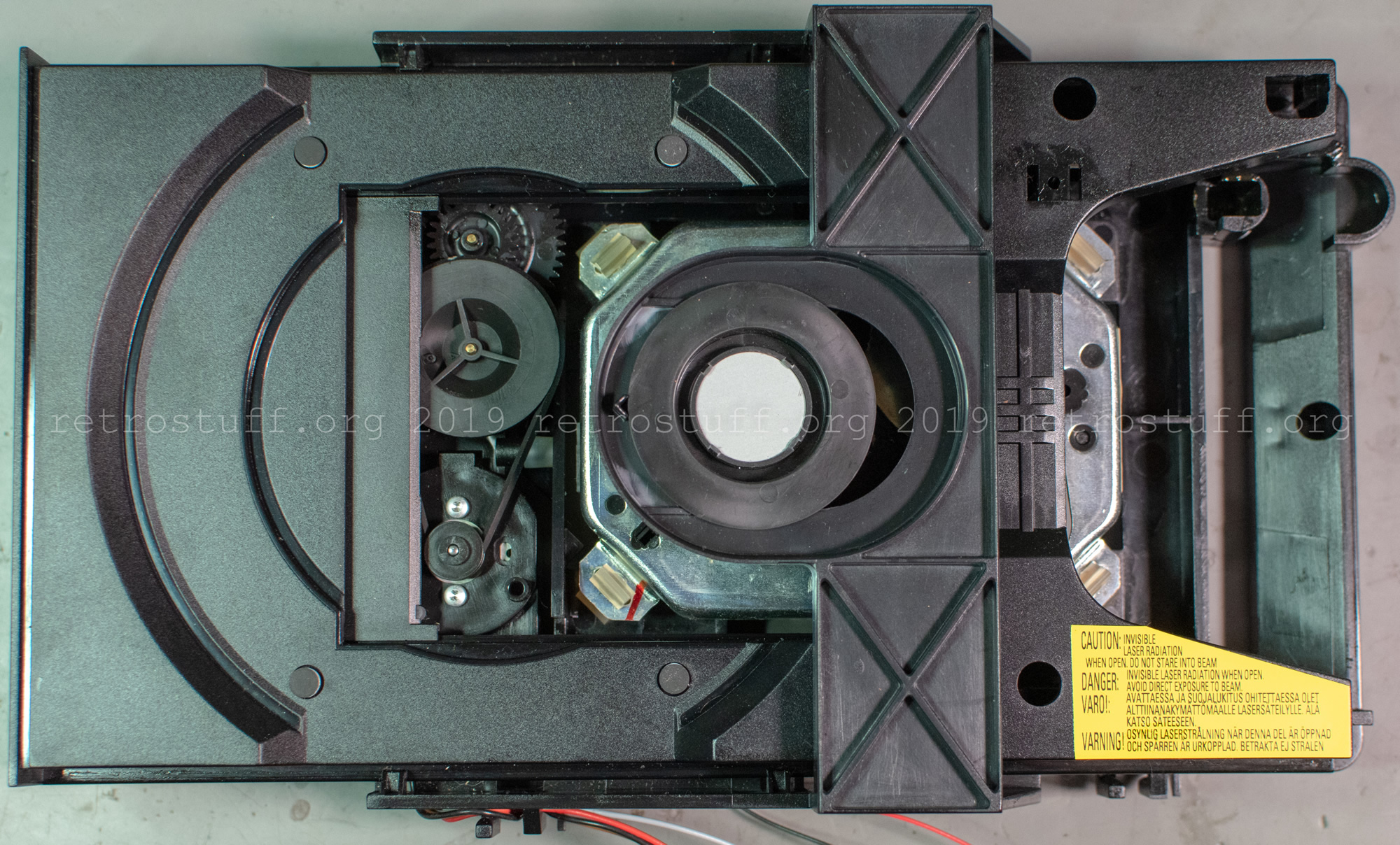
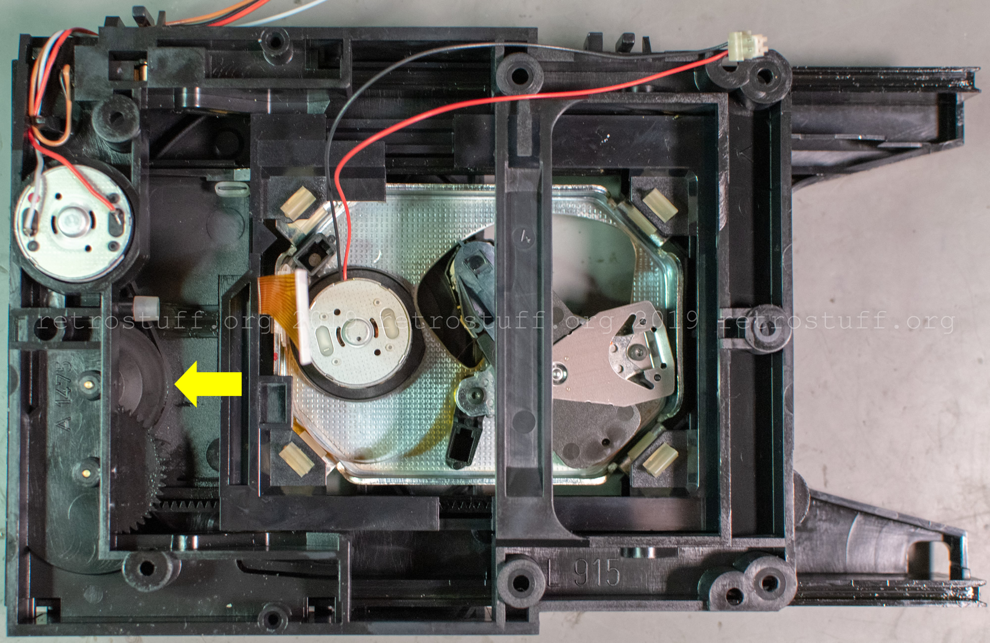
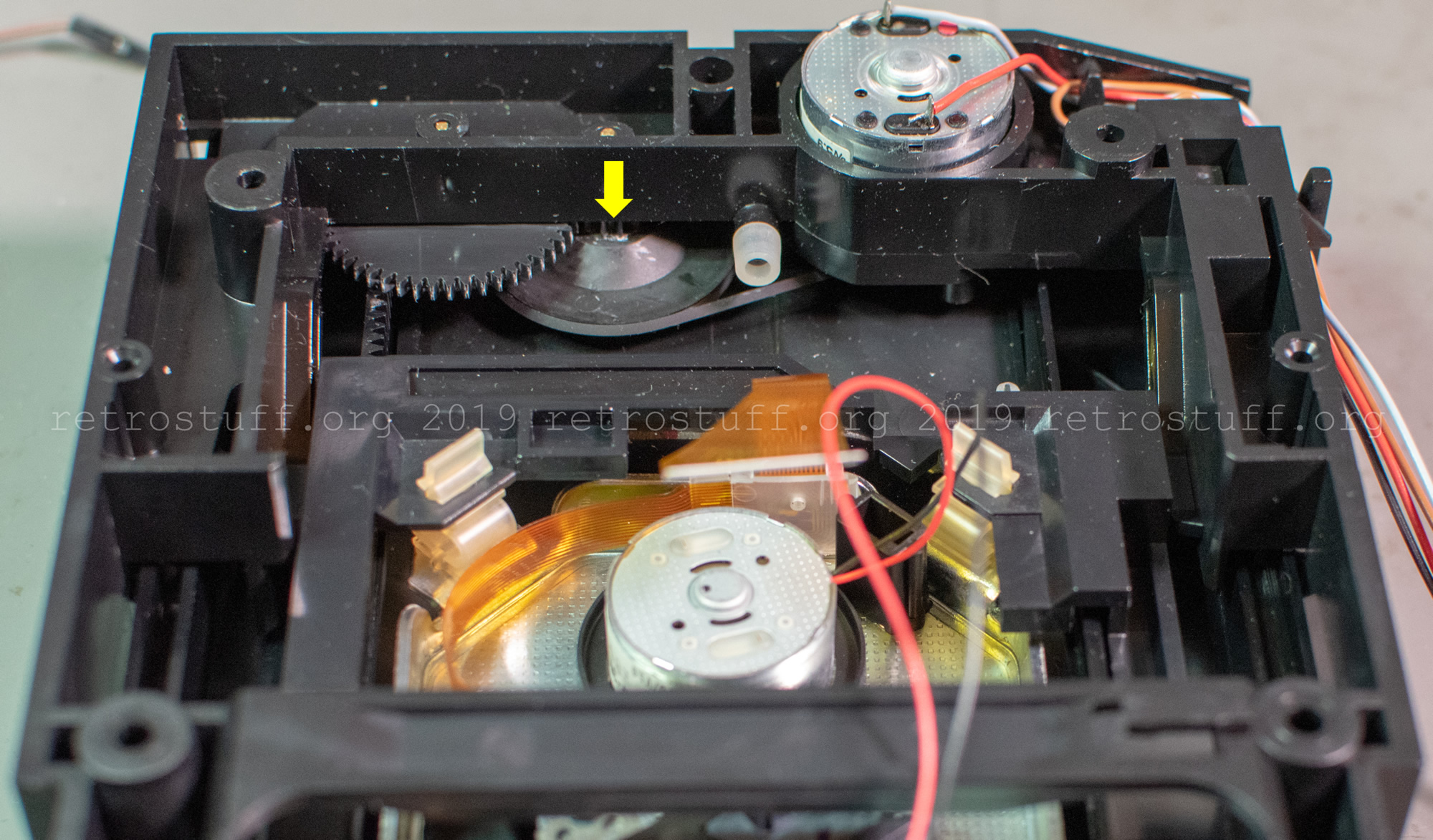
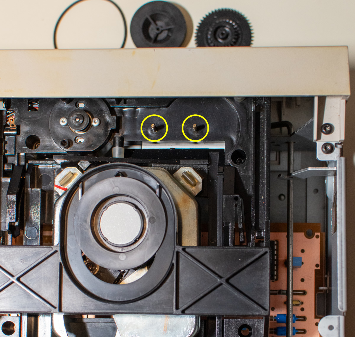
The screaming noise is caused by the big wheel with the rubber belt:
Shortcut: ODD
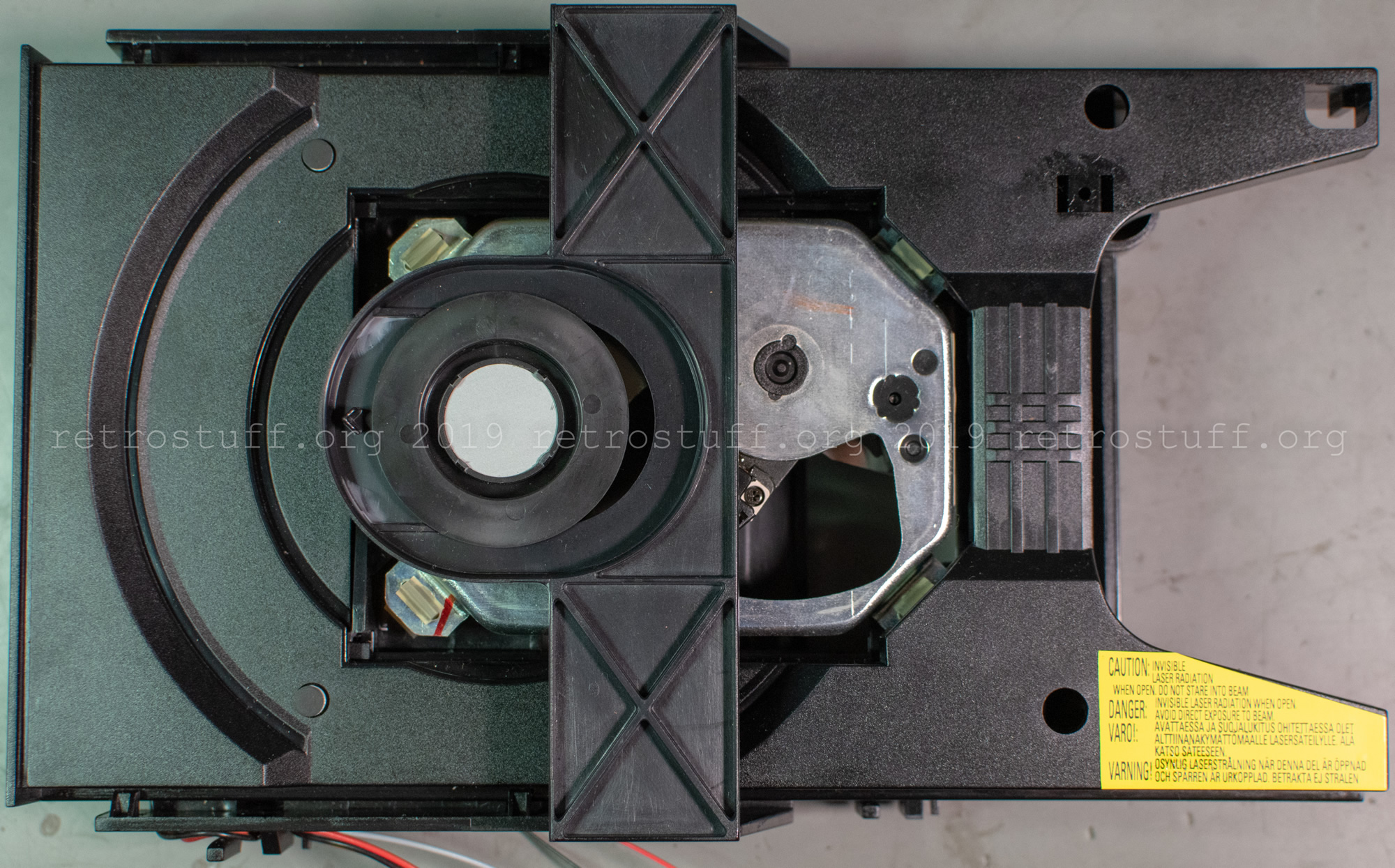
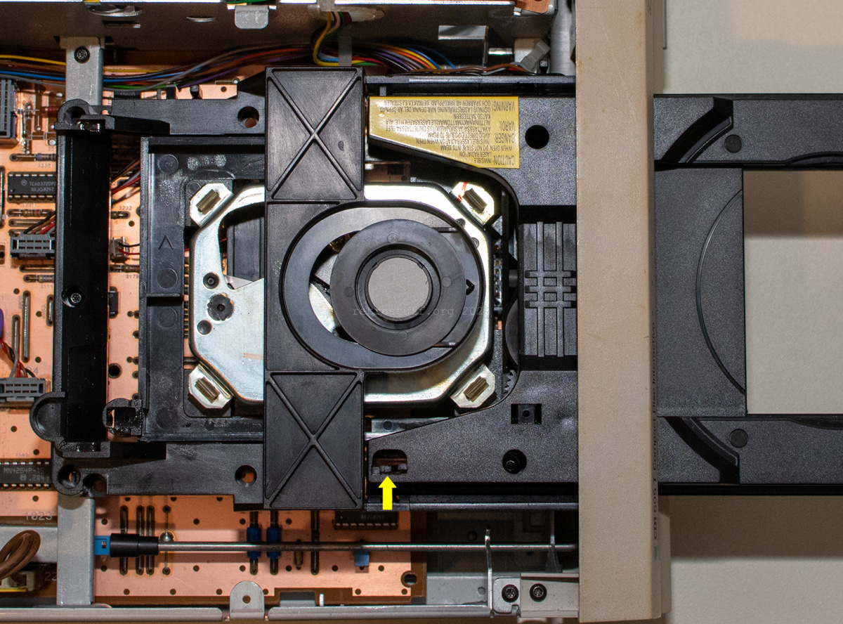
To remove the tray, pull it all the way out and press the plastic spring in the direction of the arrow using a blunt tool, such as a flat screwdriver or spatula. This will release the tray completely.
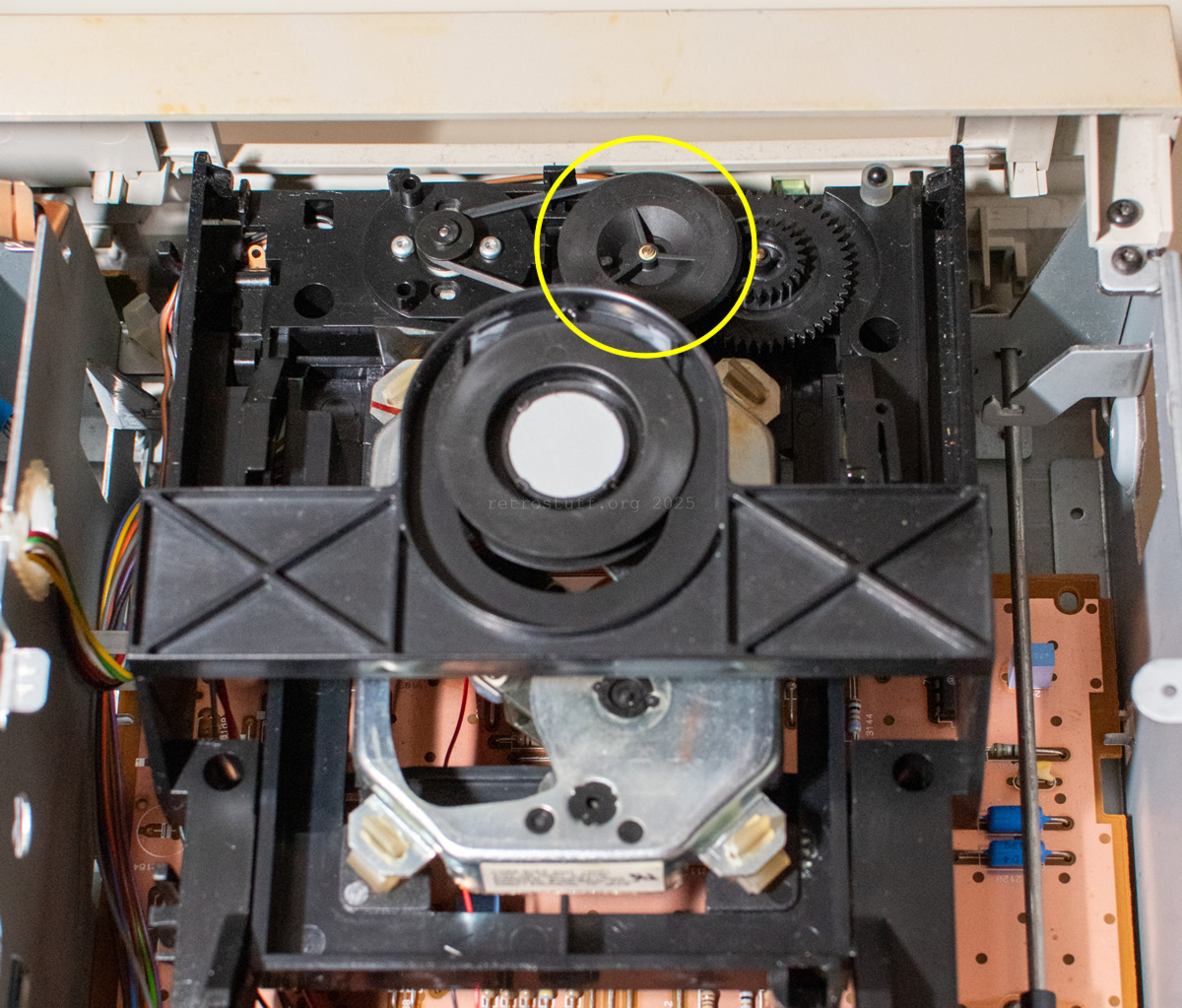
Remove the belt and pull off the large wheel. Clean the area of old grease, then re-grease the spindles and gears. I used a Teflon/PTFE-based grease for model-making.
Replace the belt if the tray no longer opens and closes automatically.
Caution: Make sure the belt does not come into contact with grease.
Before putting the tray back in, check that there is no dried grease on any of the teeth or their counterparts in the tray loader. Clean and re-grease these areas if necessary.
Disassembly – right side
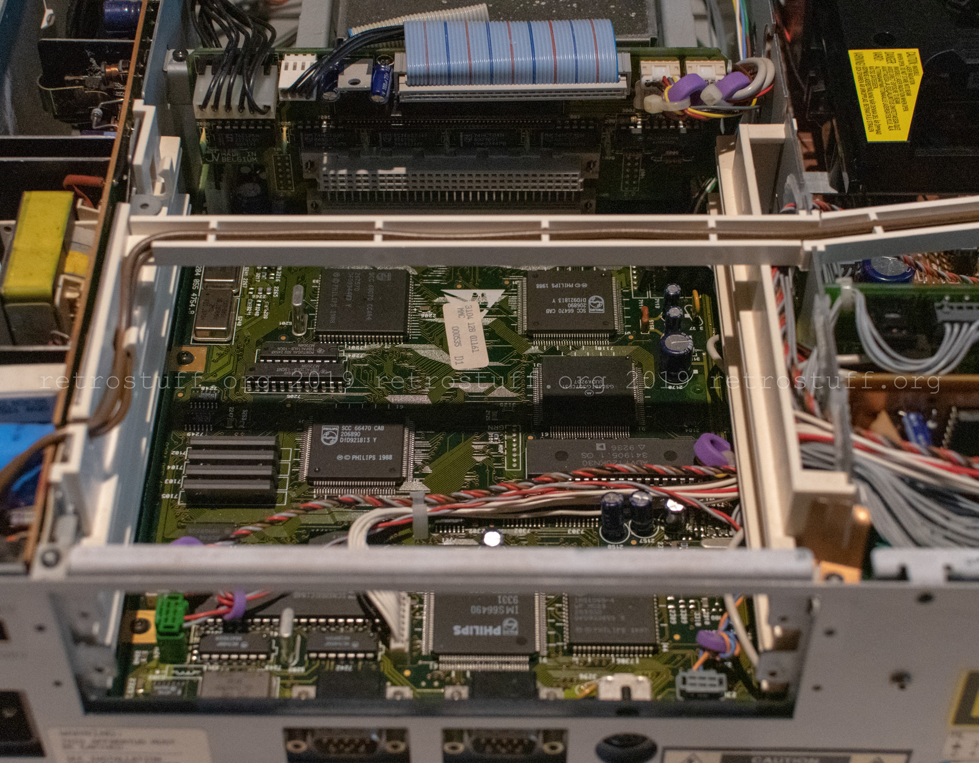
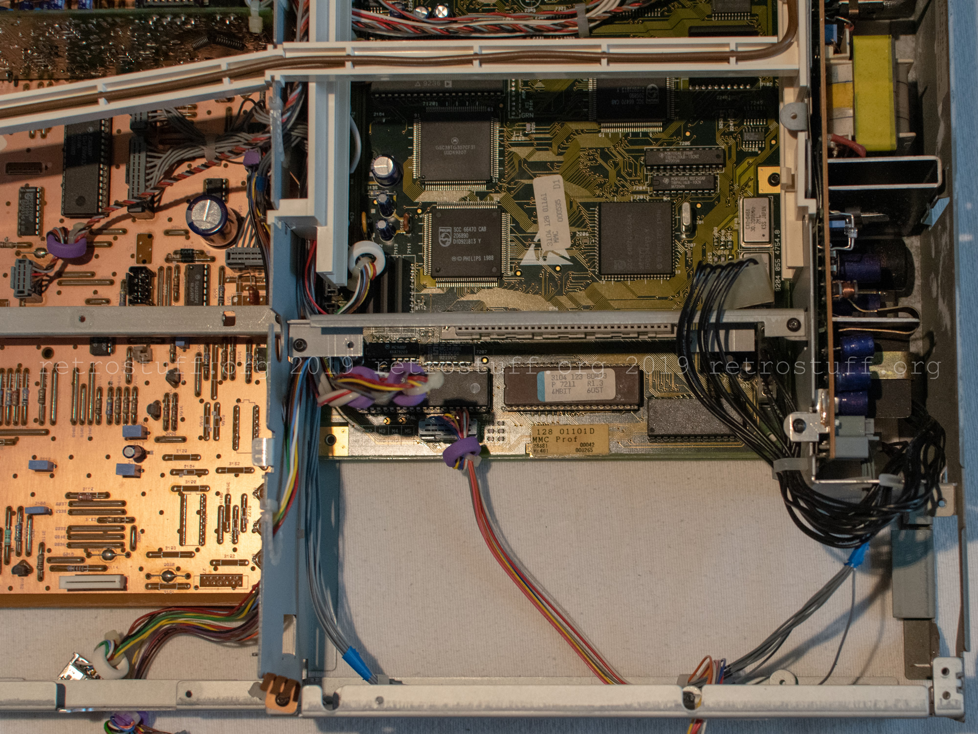
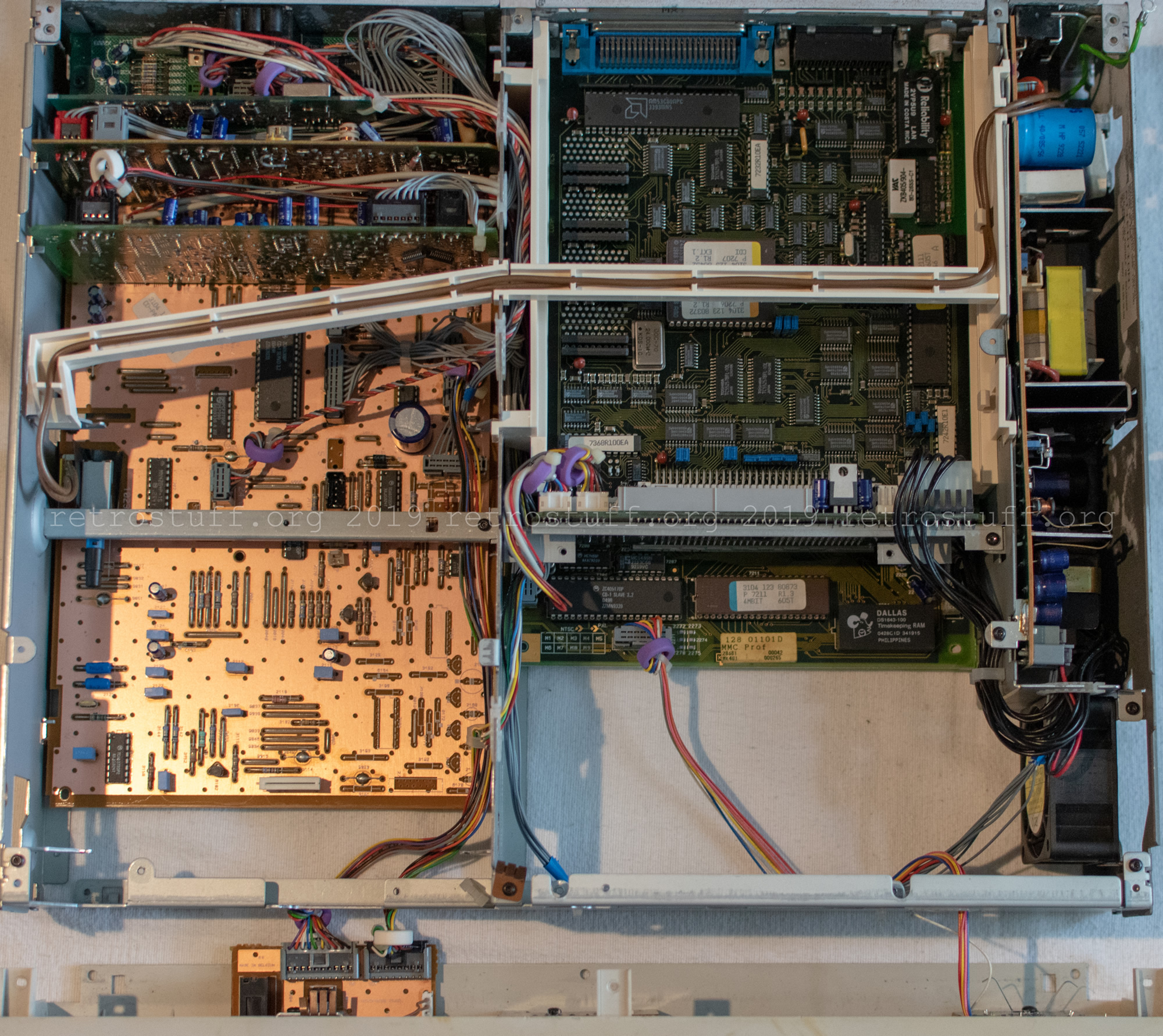
To access the next parts in need of repair, I removed the floppy disc drive assembly. This gave me the first clear view of the MMC panel with the Timekeeper (yellow rectangle).
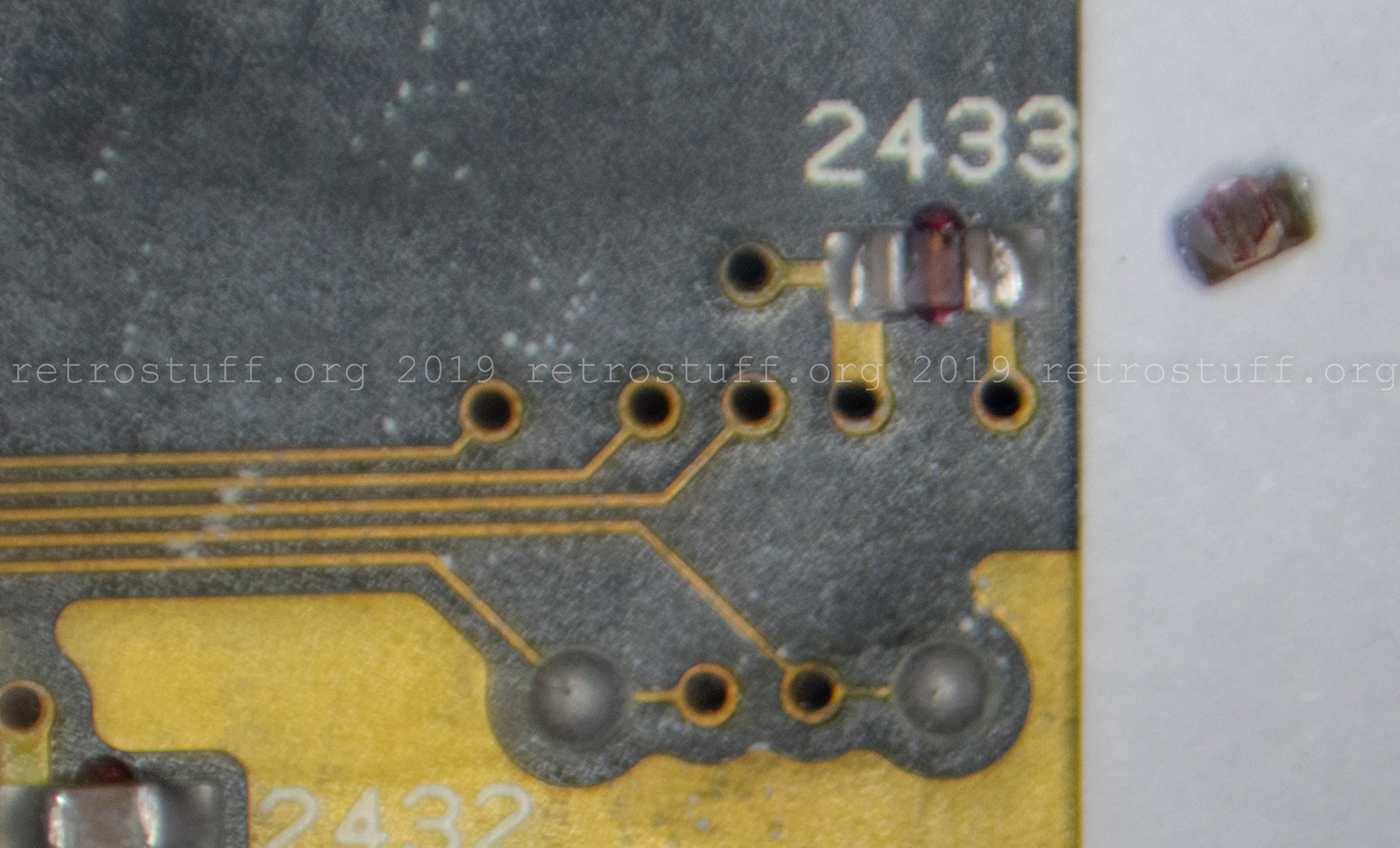
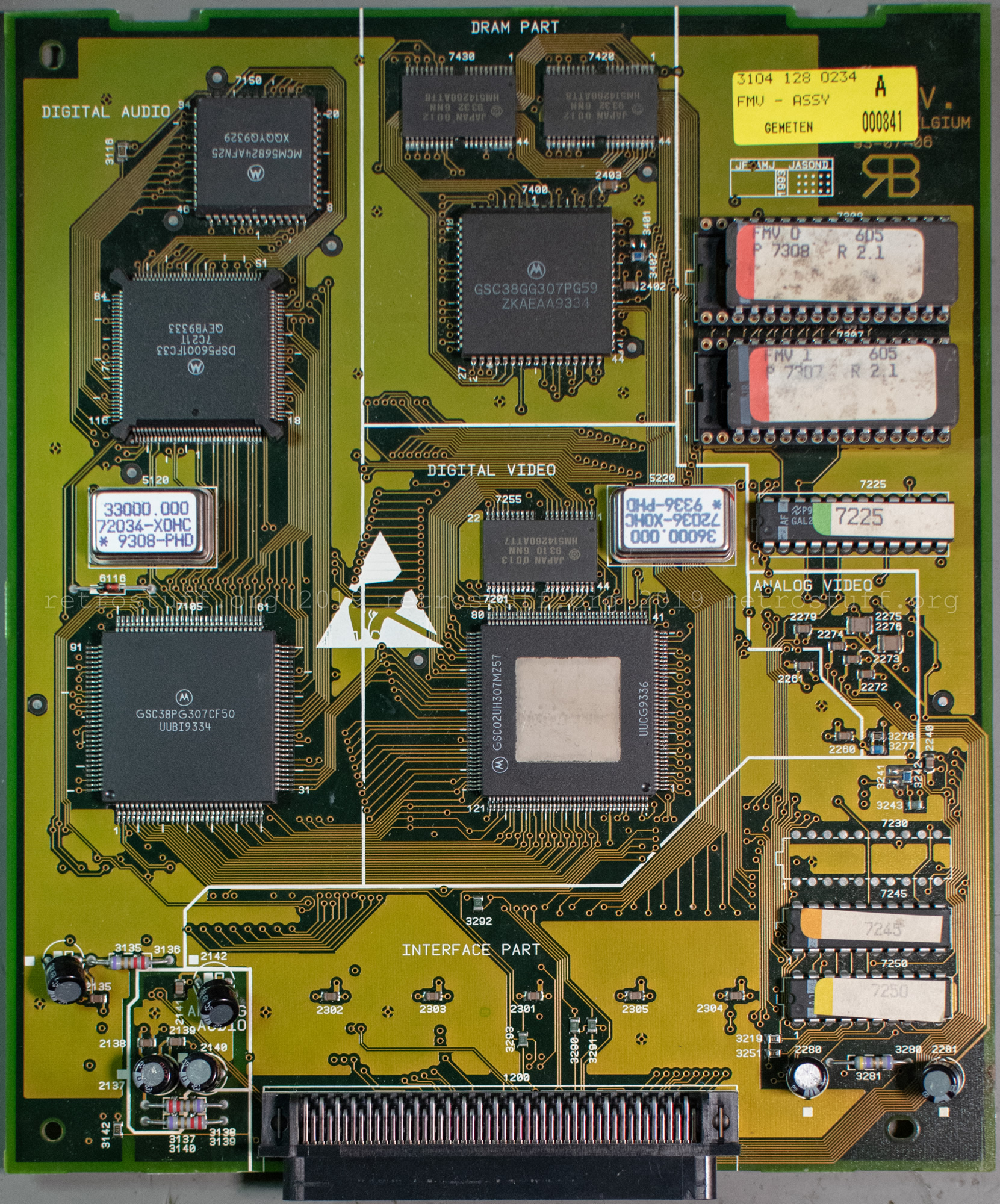
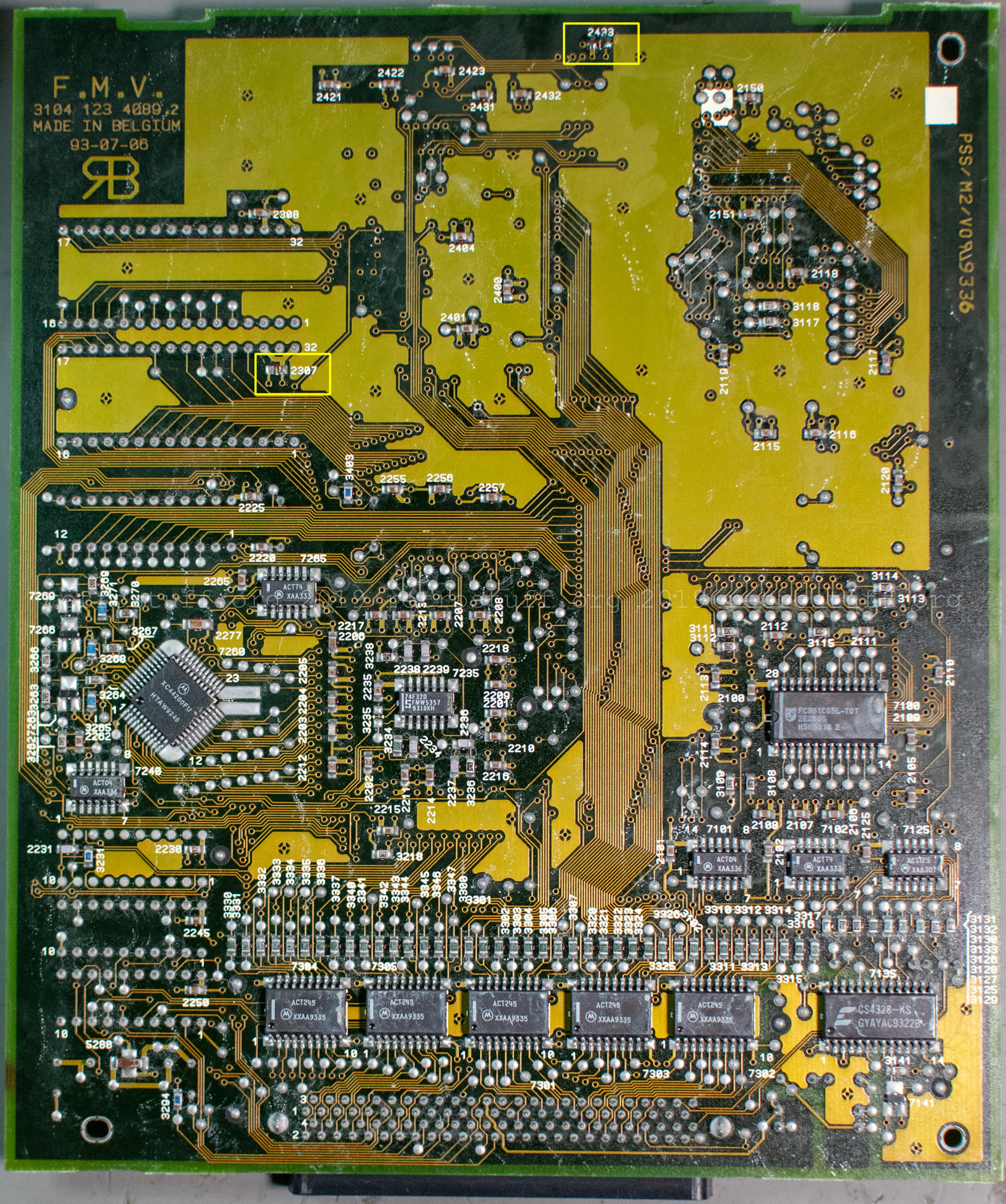
At this point, I noticed that a tiny SMD capacitor had fallen off one of the boards. It took me a while to work out which board it had come from. Upon inspecting the DVC with a microscope, I discovered that two SMD capacitors were missing, not just one. It’s possible that one of them (2433) came off when I bumped the DVC in the lower extension card, but the other one (2307) was in the middle of the PCB and must have been missing beforehand. Update: Further information about the repair can be found next to the close-up pictures of the DVC below.
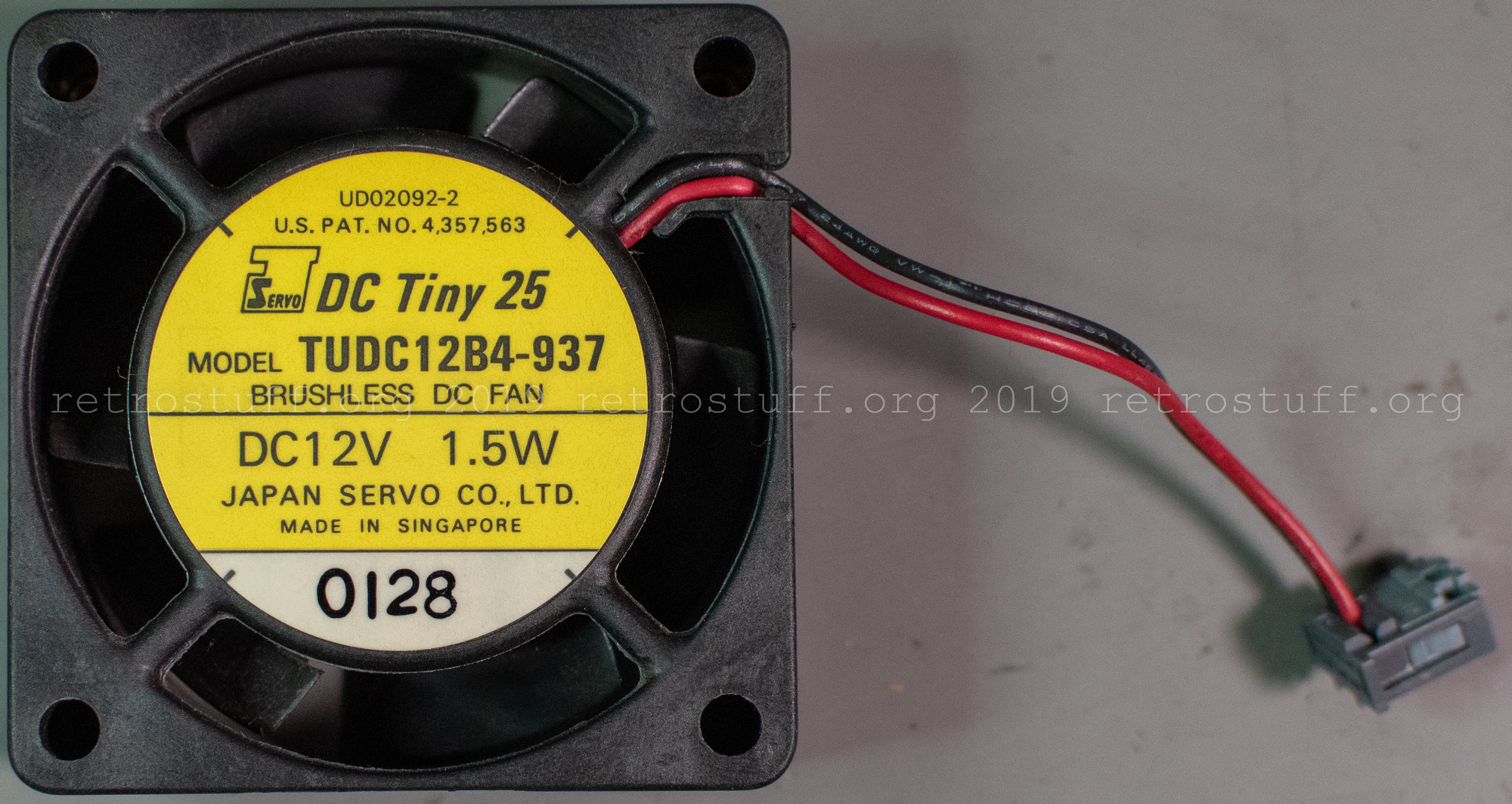
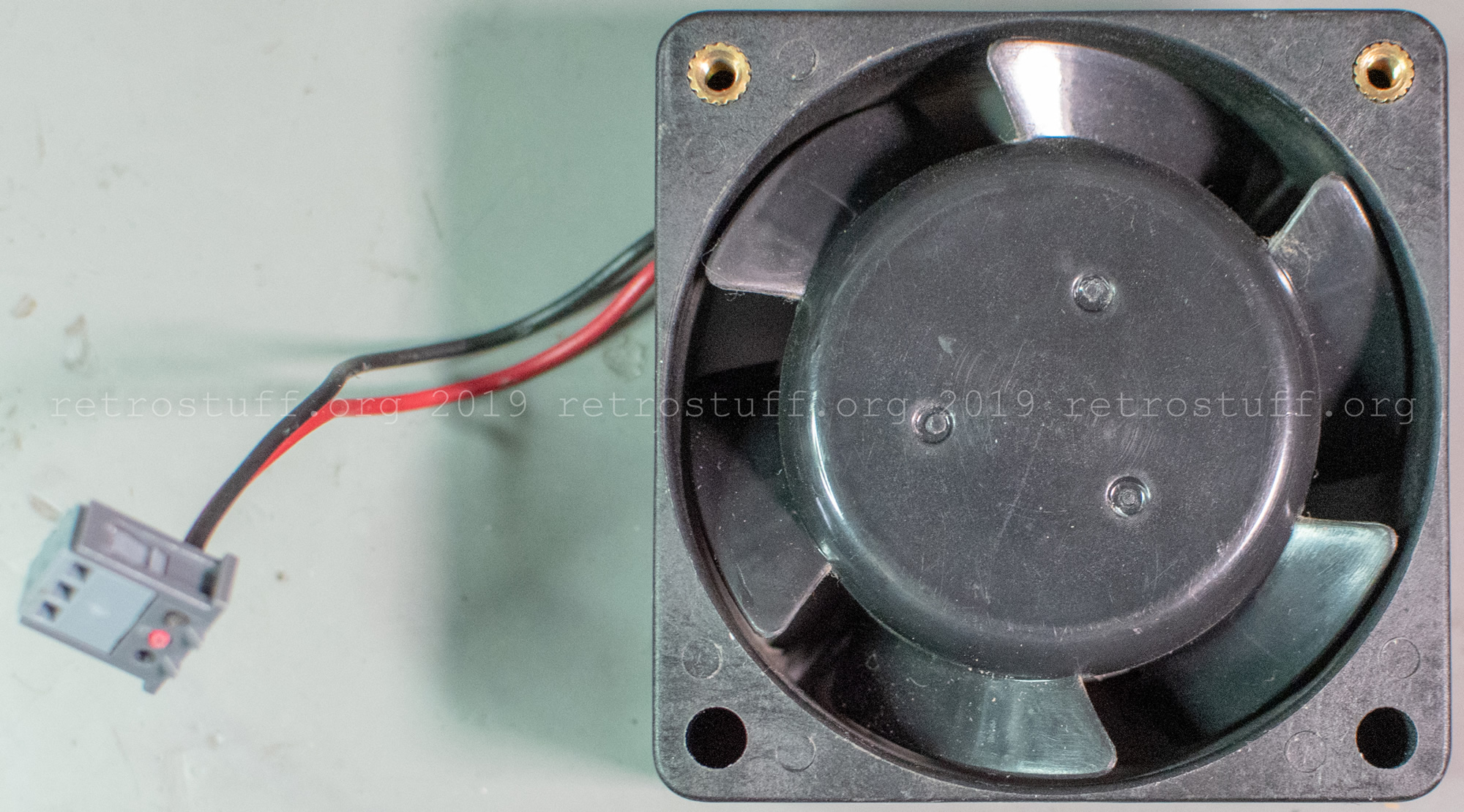
Then I removed the riser for the extension slots and the fan. Note the connectors on the right side, they have the same size and are therefore easily mixed up.
The fan was actually in a pretty good shape and only needed light cleaning. The noise that it emits is probably by design. I will have a look for a suitable silent replacement (like the one that I found for my CPS2) at a later time.
Plenty of plastic parts, screws and connectors later, and I was finally able to remove the Mini MMC panel.
Timekeeper replacement
I fixed the MMC into a PCB holder to be able to access it from both sides and rotate it when needed. As mentioned before, the Timekeeper chip was soldered from both sides and my desoldering gun needed additional support from a soldering iron on the other side.
Then I fitted a 28-pin socket and a Dallas clock chip (DS1643-100). The DS1643 is compatible with all functions of the 8K NVRAM Timekeepers (MK48T08B / M48T08).
Update: The DS1643 is no longer recommended as a replacement. Please refer to the 8KB section of the NVRAM+RTC Solutions for Philips CD-i Players article.
Testing
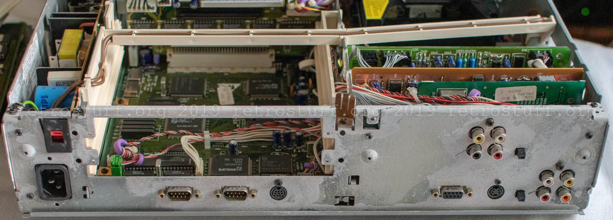
The power supply was the last part on the right side that I removed to take pictures. All that’s left was a bunch of cables and metal parts.

Then I assembled the right side again to run some tests. I tested various settings, including time/date and configuration of the additional ROM/RAM memory via the TOOLS menu. All the settings remained in the NVRAM, even after I disconnected the power for some time.
Disassembly – left side
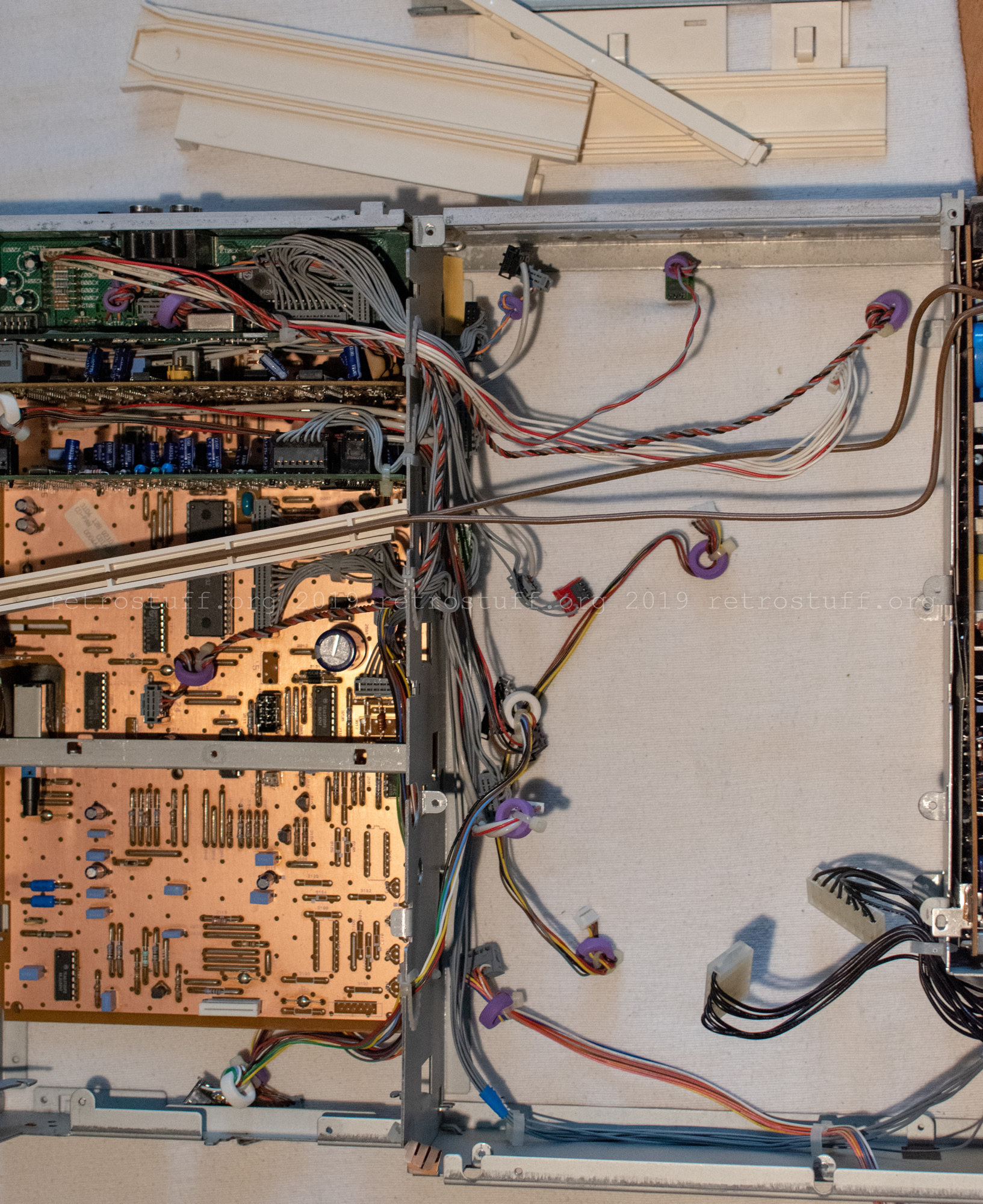
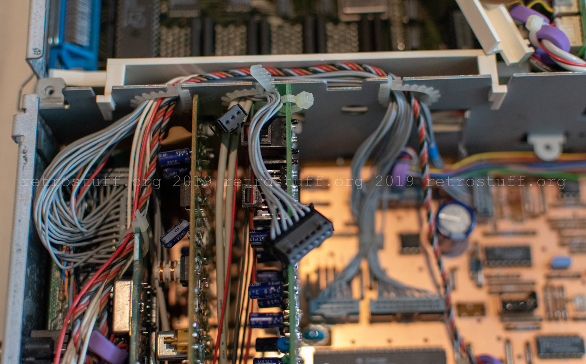
Even when the tests were successful, I wasn’t done with taking pictures of all PCBs. The left side of the player contains the CD panel and some more panels plugged into it, namely audio, video encoder and emulator. To remember the cable routing, I took some pictures on the way.
This is the empty left side of the CD-i player and it’s as far as I will go to disassemble it.

After that, I put everything back together and ran some final tests, including CD, floppy and hard disk drives. Everything worked as expected and even the OS-9 shell didn’t give me weird error messages anymore. This concludes the Philips CDI605T disassembly and repair for now.
Close-up pictures of the components
And here are the close-up pictures of the removed components in the order that I removed them.
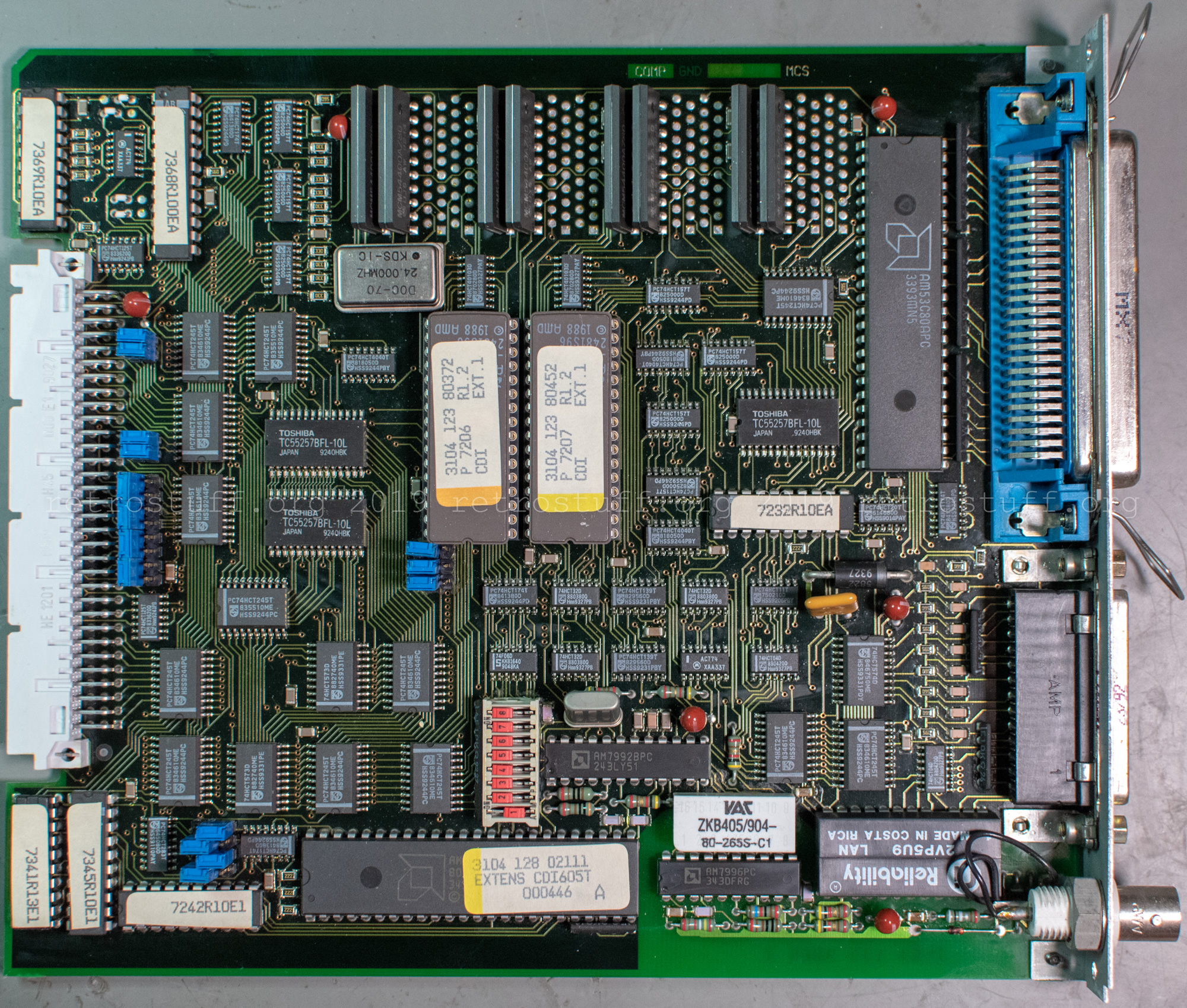
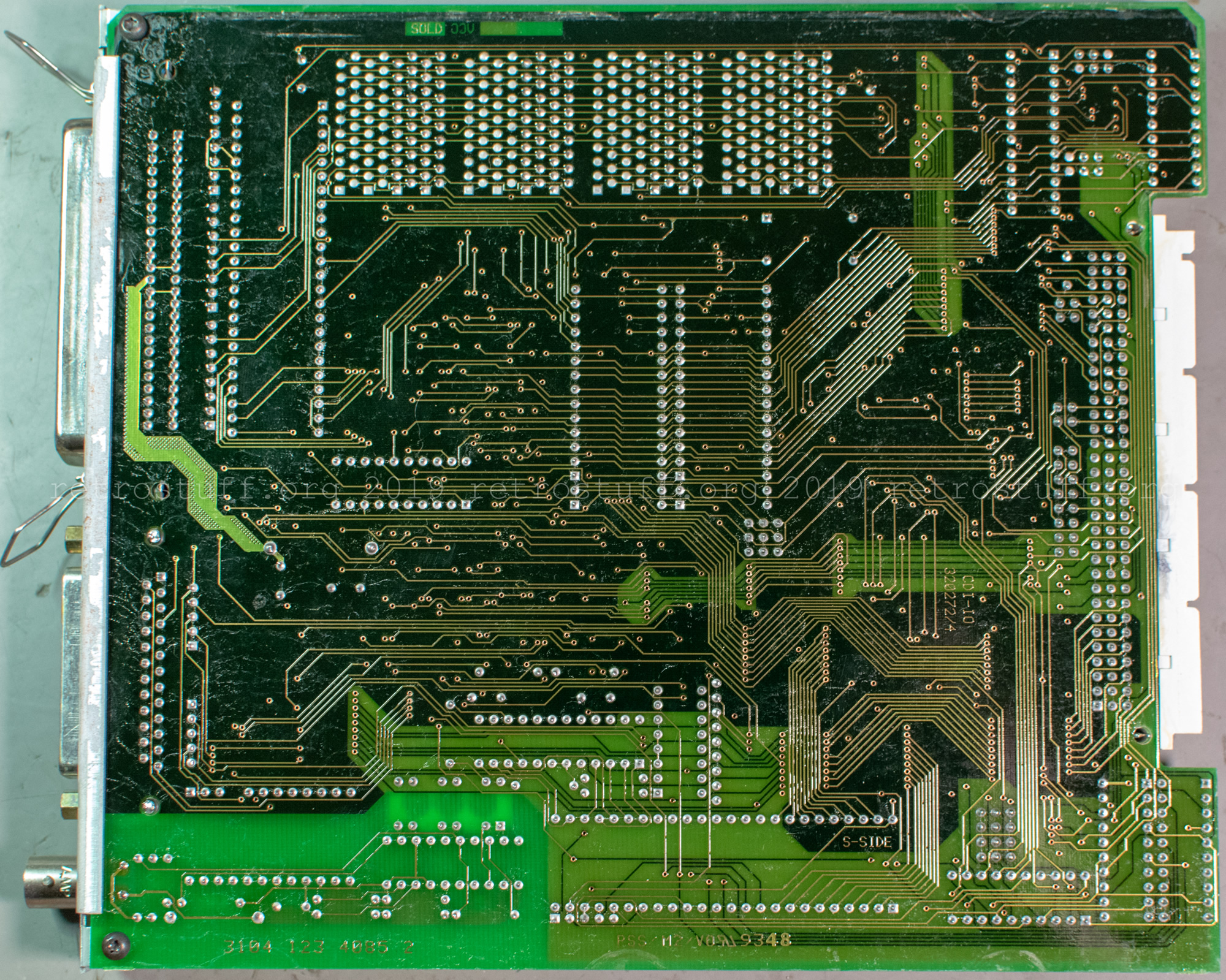
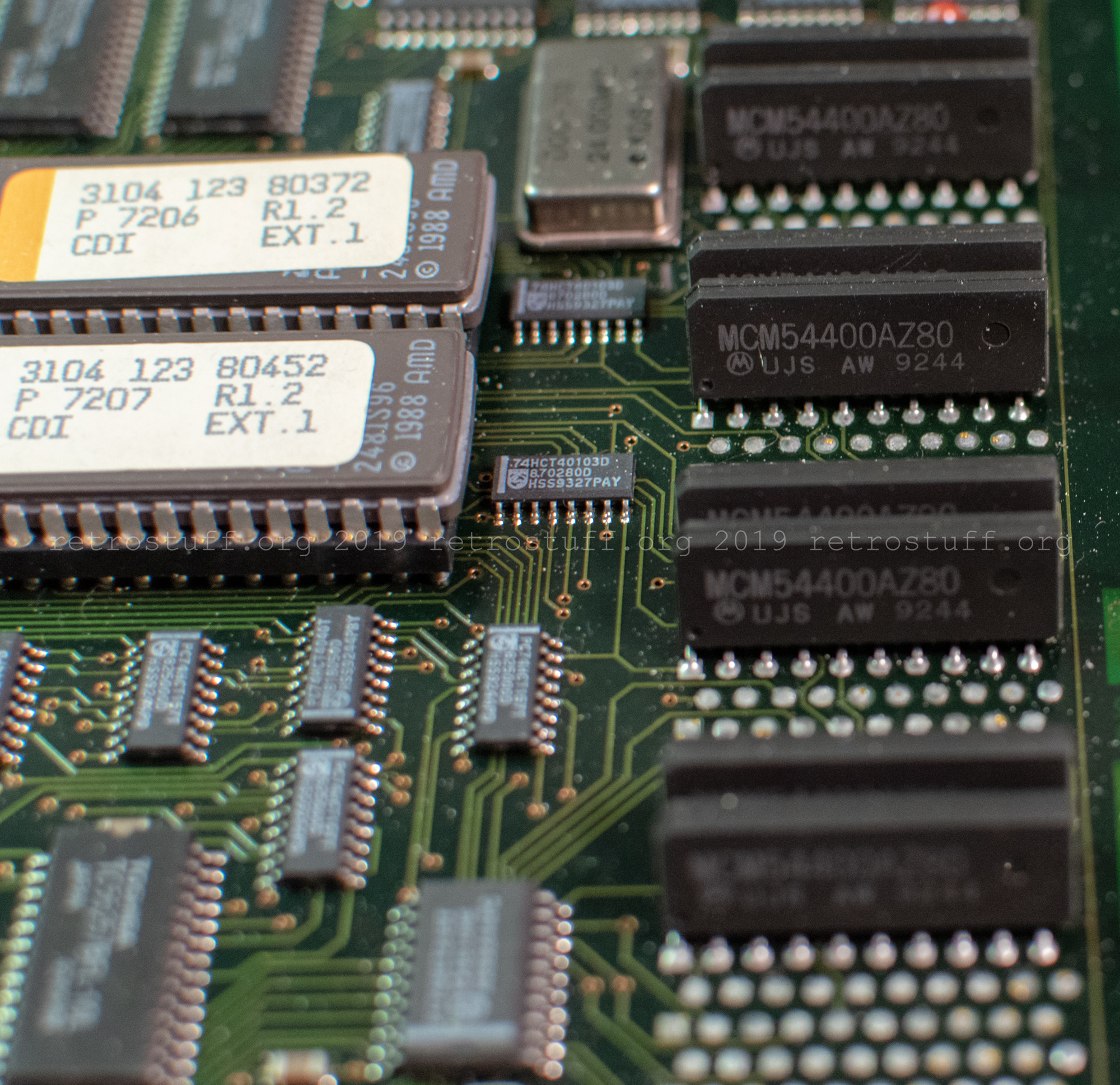
- Philips CDI605T extension card 22ER9132 “EXTENS CDI605T”. It features 4 MB memory and Thin Ethernet (10BASE2), SCSI, parallel port connectors. There are eight Motorola MCM54400AZ80 1Mx4 chips and free space for eight additional chips. (I wonder if it is possible to upgrade it with more memory.)
- The GA R2.1 Digital Video Cartridge is a 22ER9424 (aka 22SW1515) with an additional 1 MB of memory. It has a ROM for 605 authoring players and will not boot in consumer players. The missing capacitors, 2307 and 2433, are marked.
Update: In May 2025, I repaired the DVC using two 22 pF 0805 capacitors, verified against an R2.1 22ER9141/00 AH00 consumer DVC.
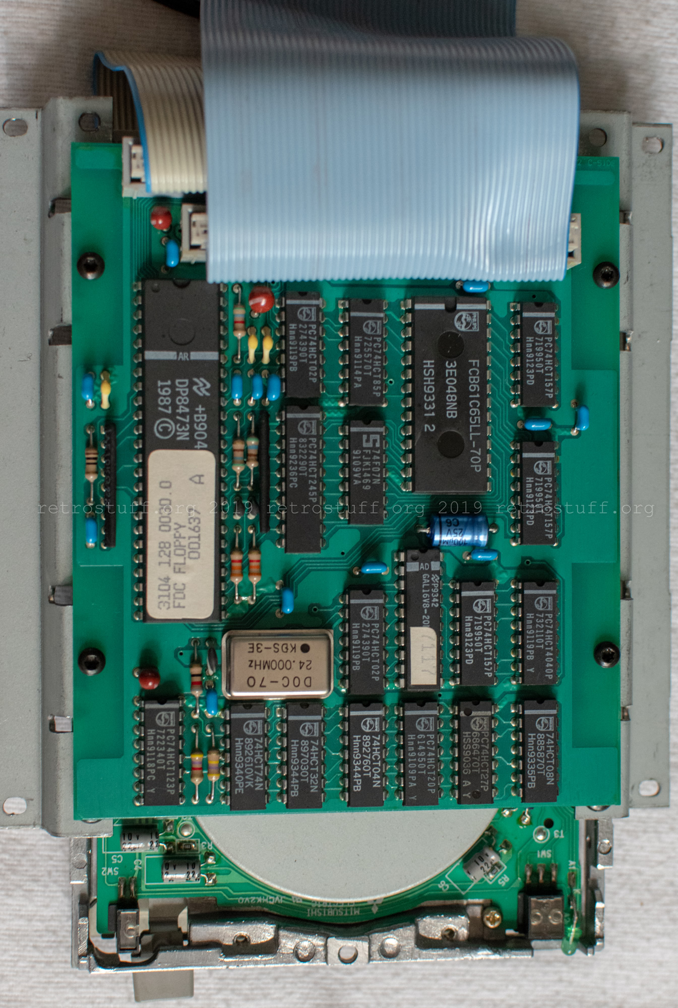
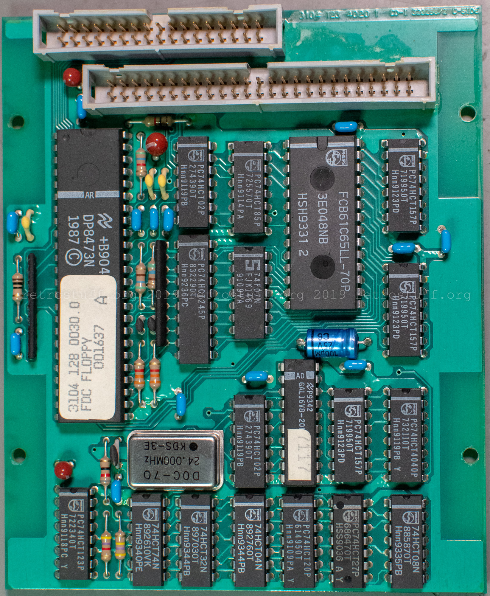
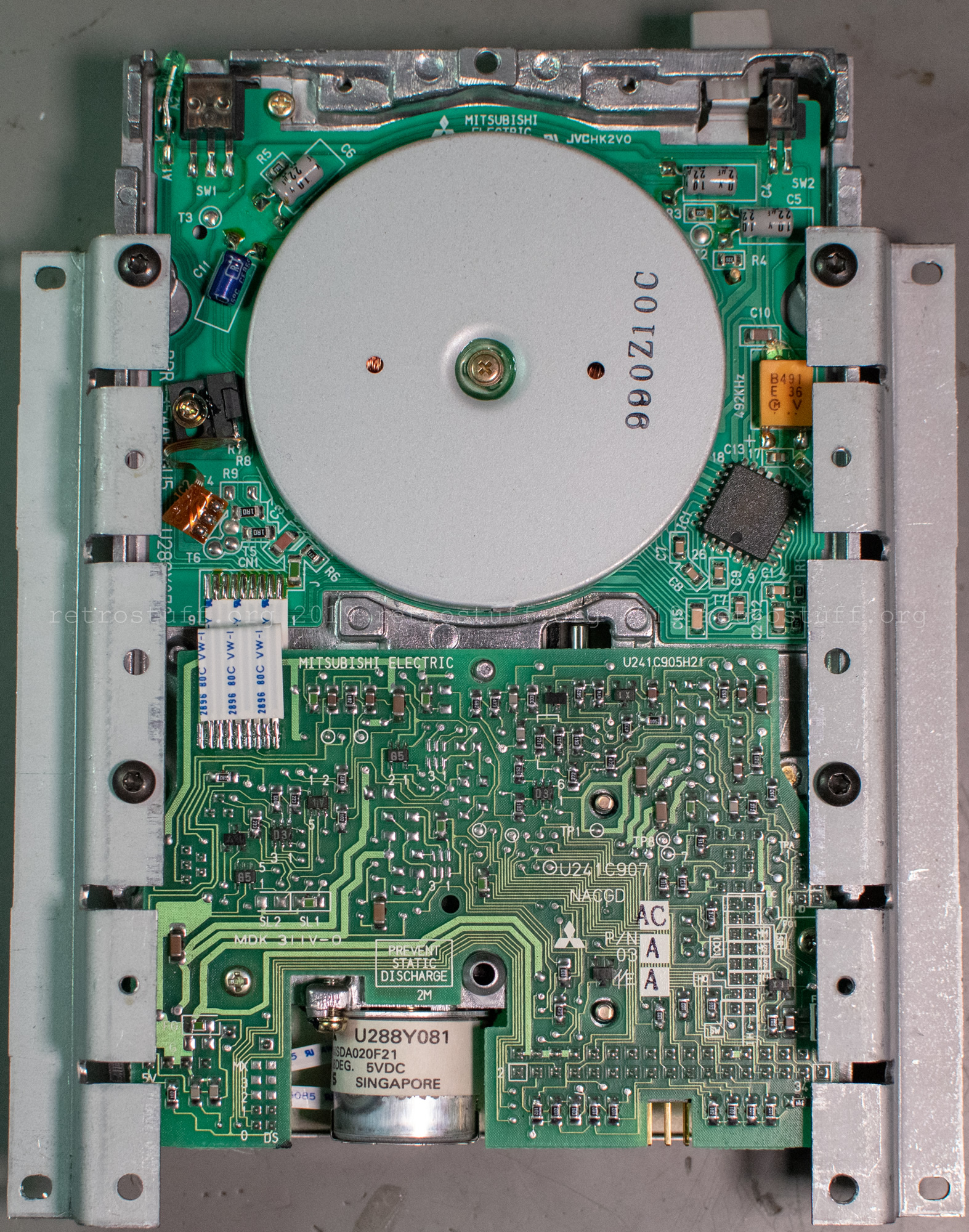
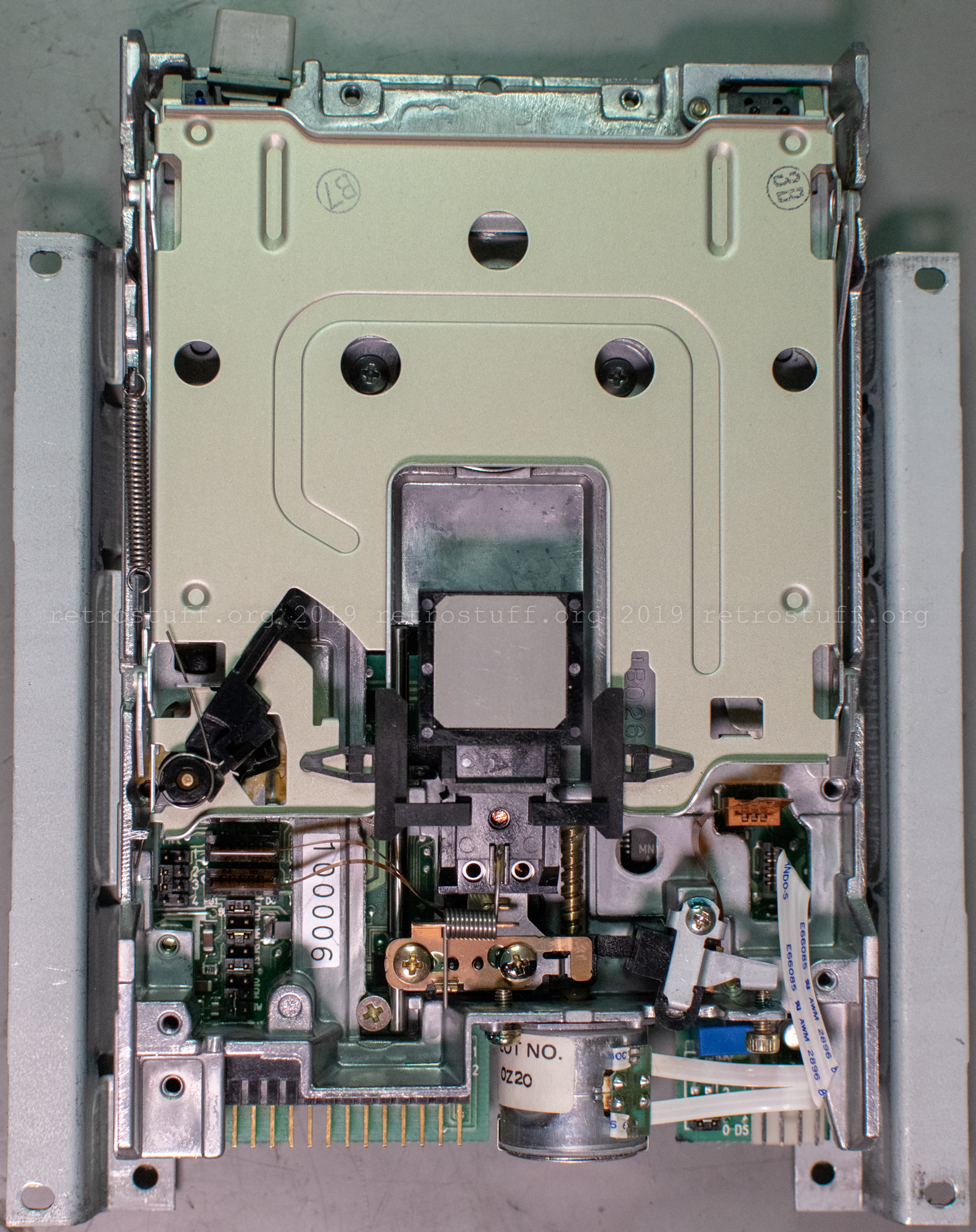
- Mitsubishi MF355C-299MG floppy disk drive. It has the controller “FDC FLOPPY” attached to it.

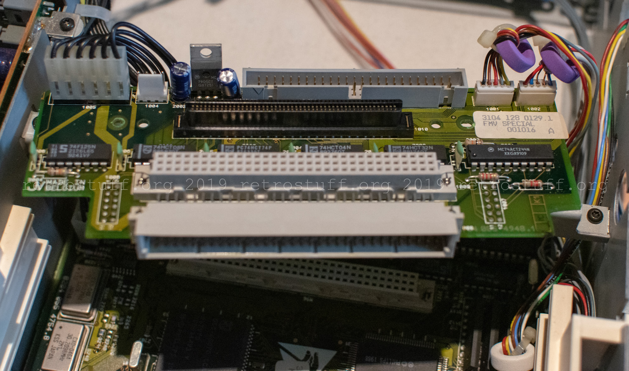
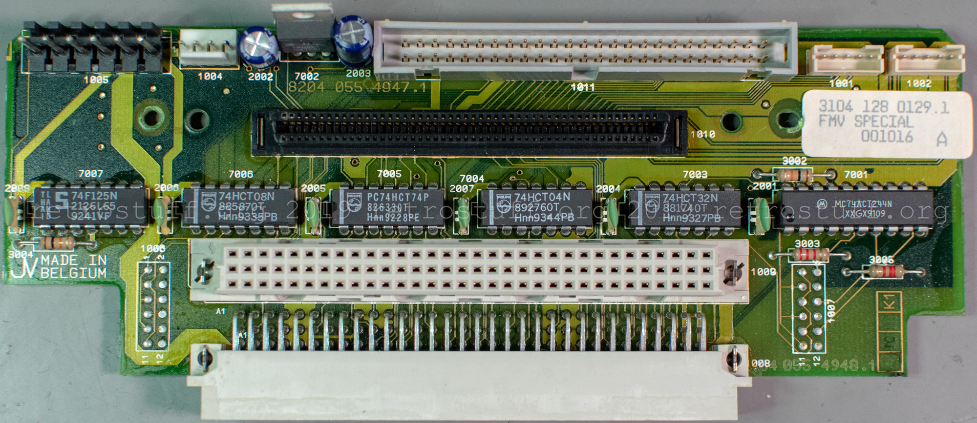
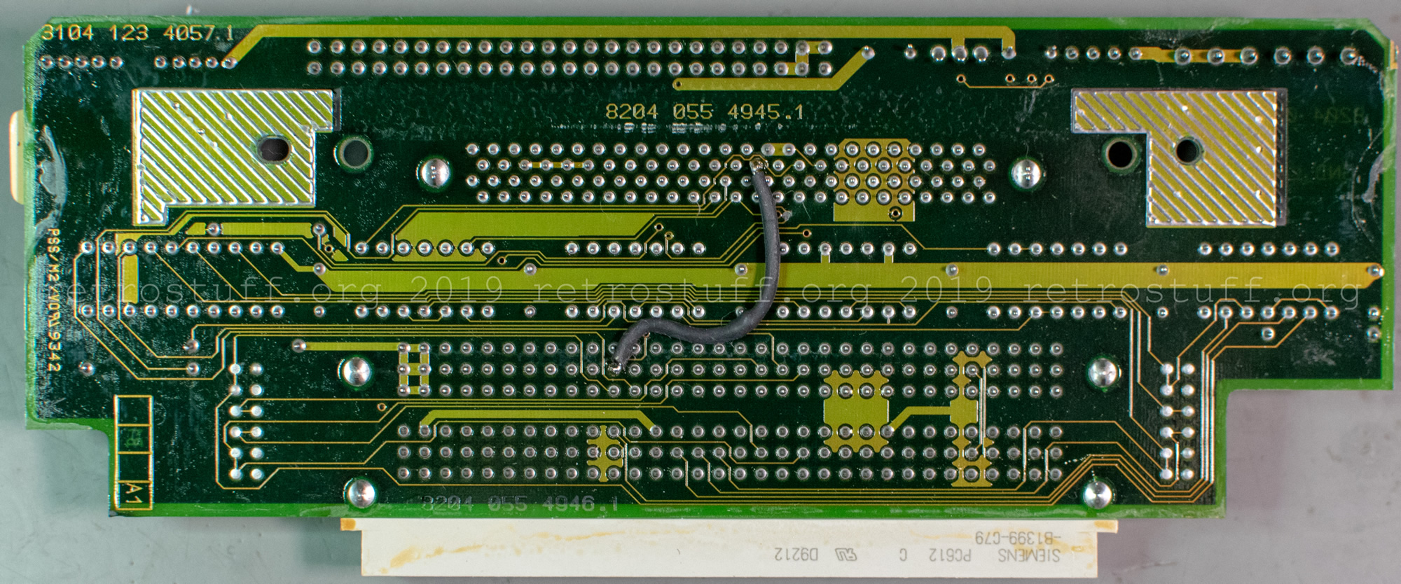
- Extension slots riser “FMV SPECIAL”. It connects the extension cards to the MMC.
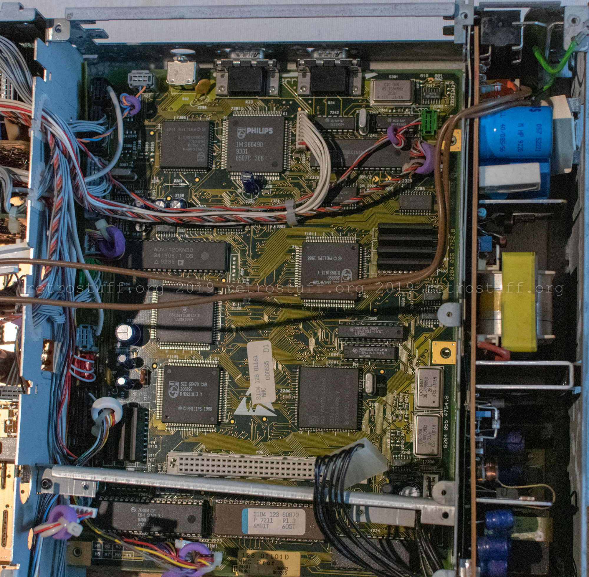
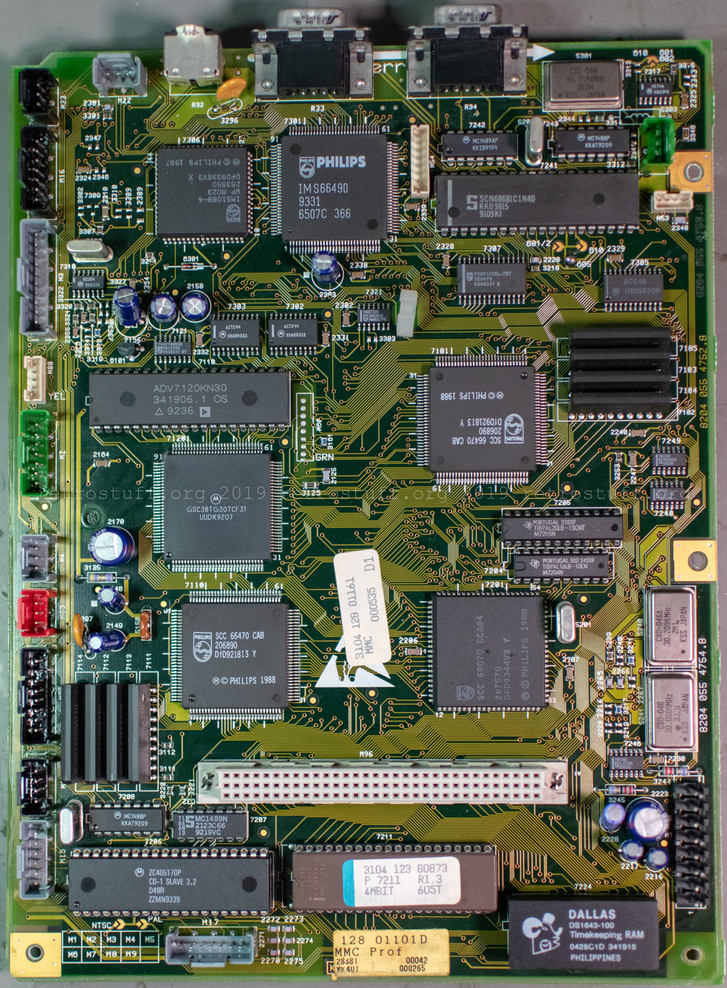
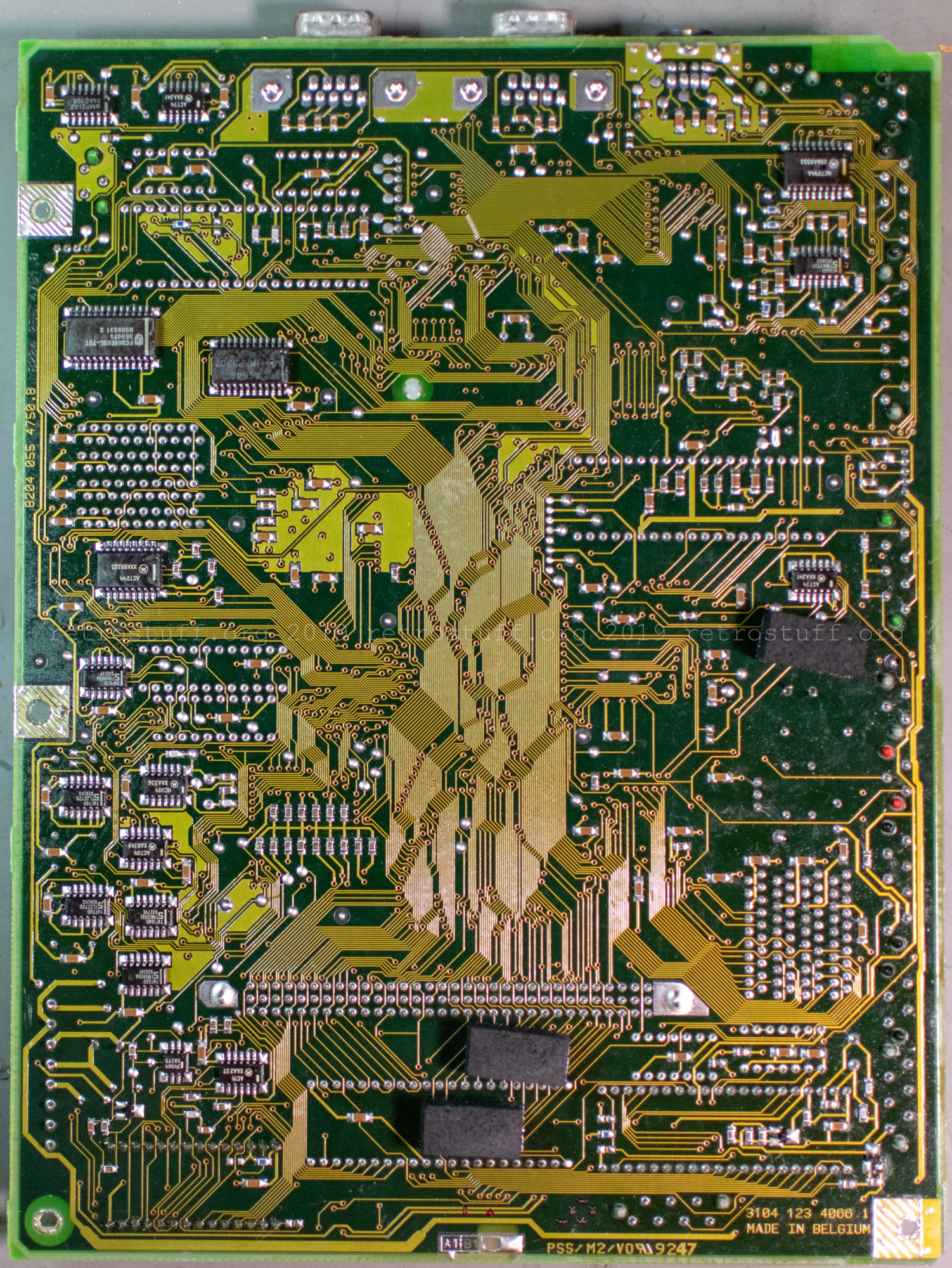
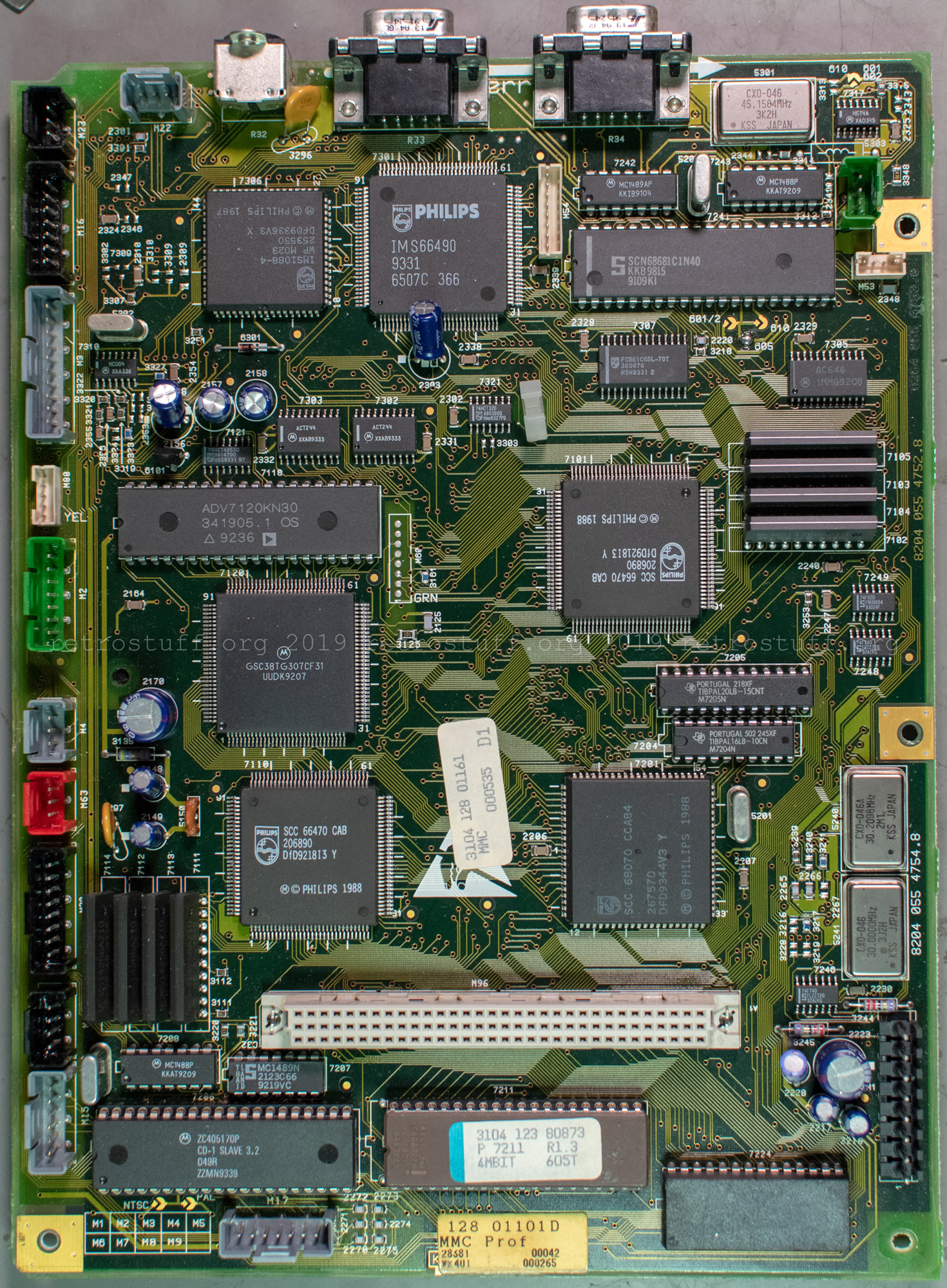
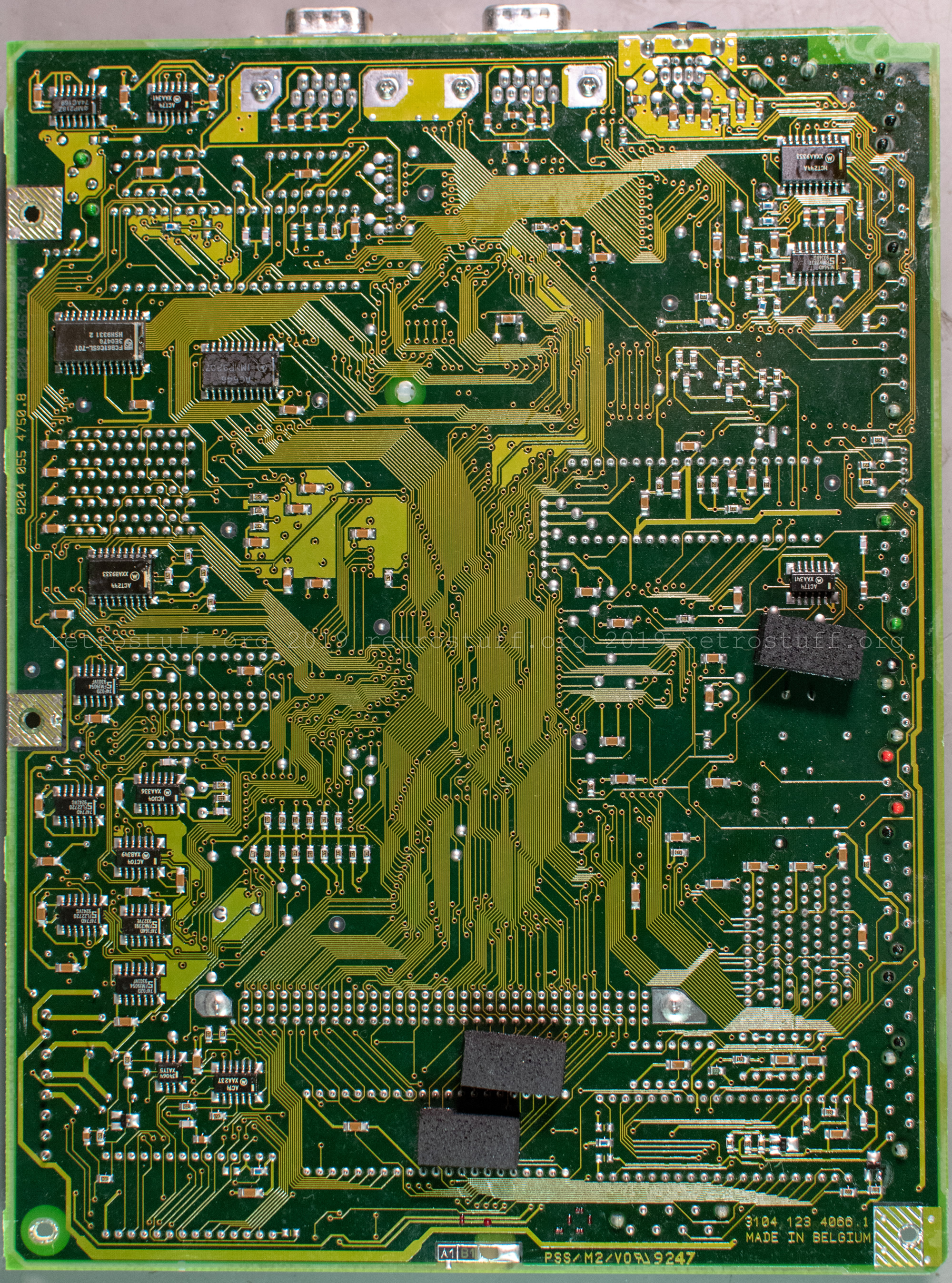
- The Mini MMC (prof.) panel (Multi Media Controller for professional/autoring players) has 1 MB of memory, as every other CD-i player (Base Case system). Compared to MMC panels of consumer players, it has some additional features, such as two DE-9 serial ports and an extra crystal oscillator to provide the correct system clocks for PAL and NTSC regions.
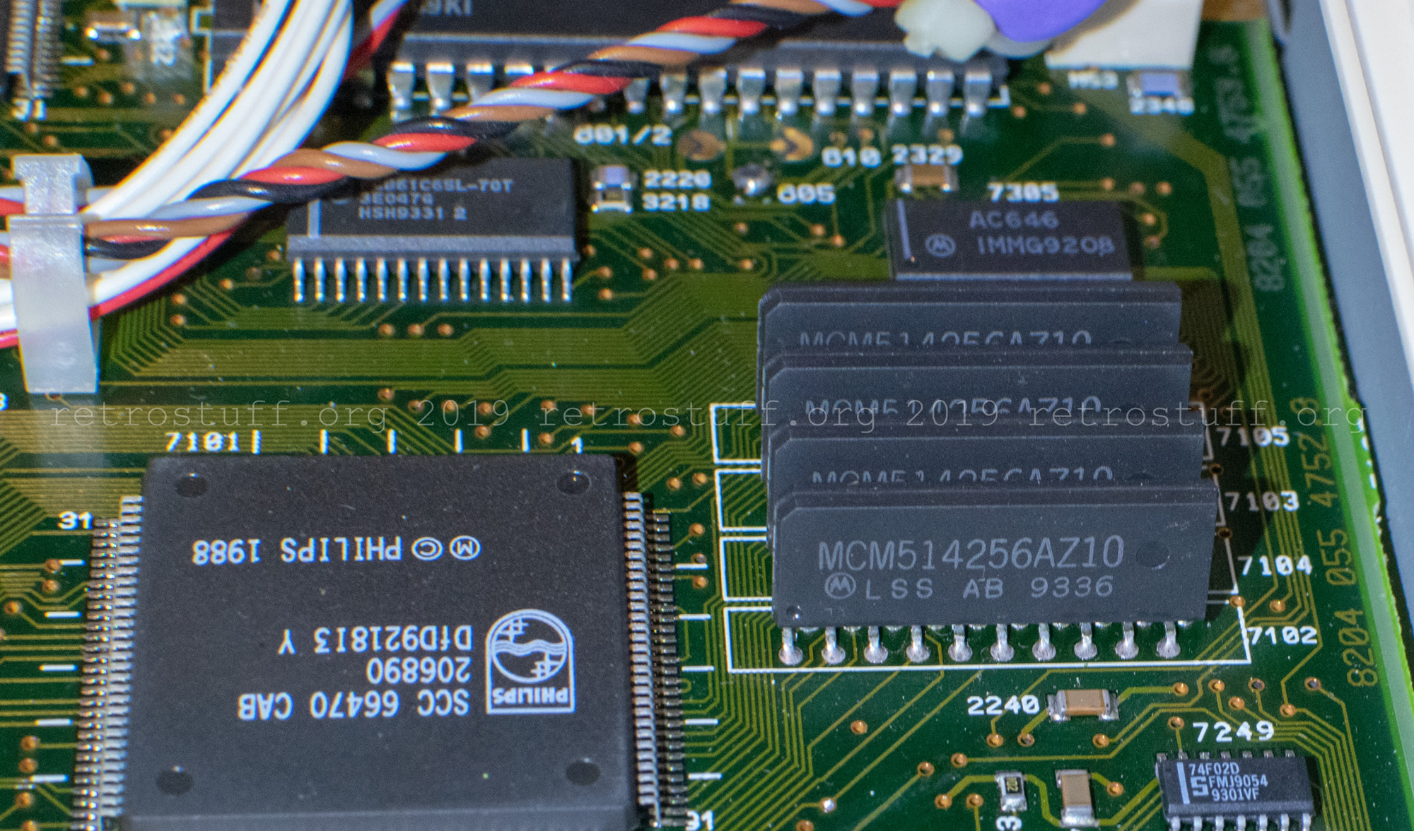
The last picture shows four of the eight Motorola MCM514256AZ10 256Kx4 DRAM chips. I took the pictures before removing the Timekeeper.
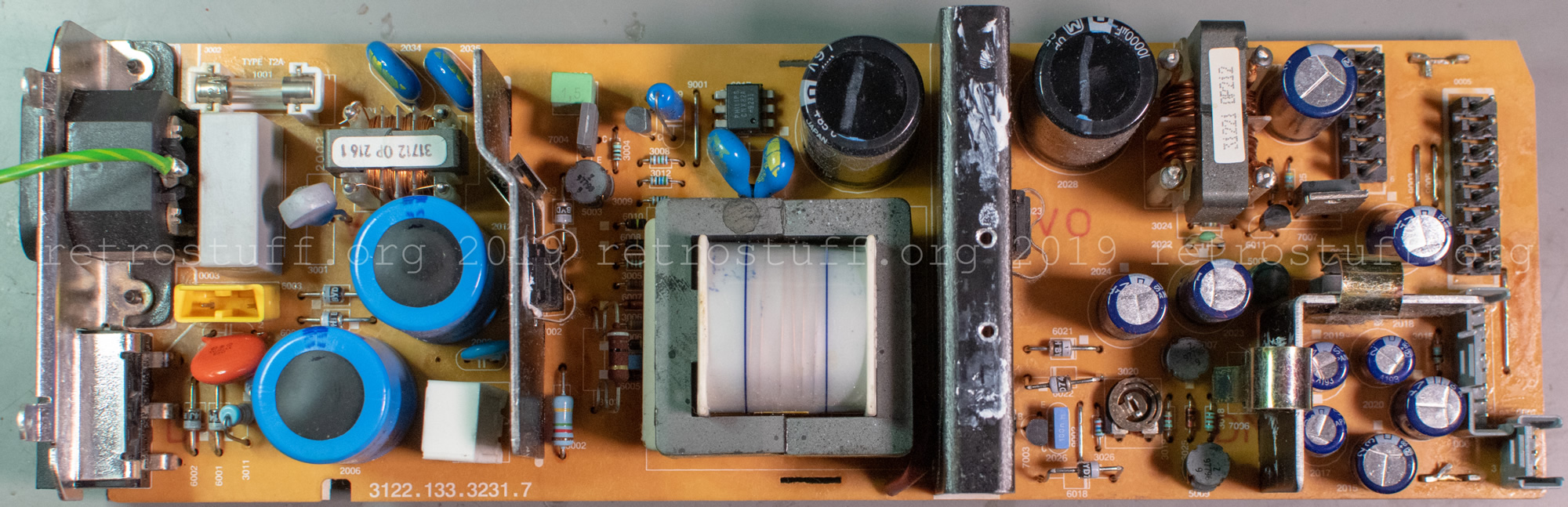
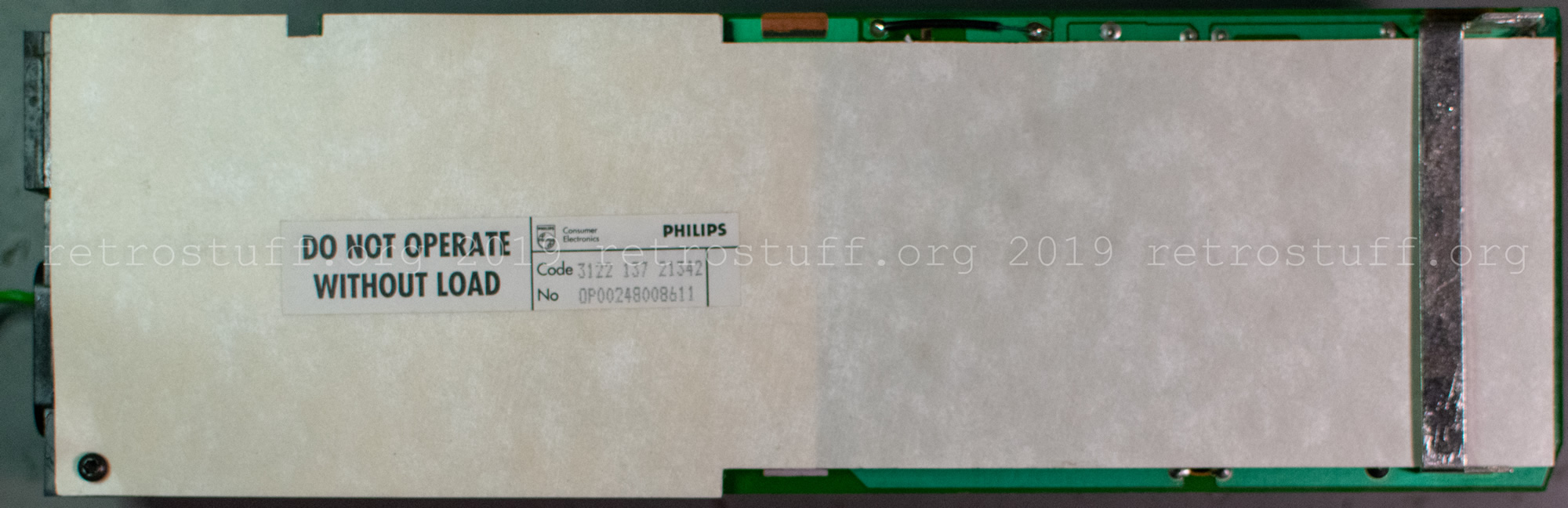
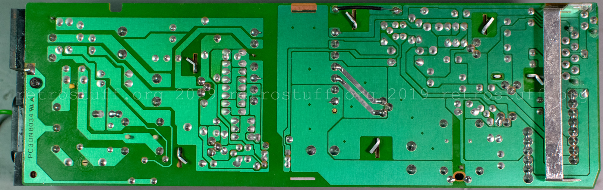
- The power supply supports 100-120V and 220-240V (50/60 Hz).
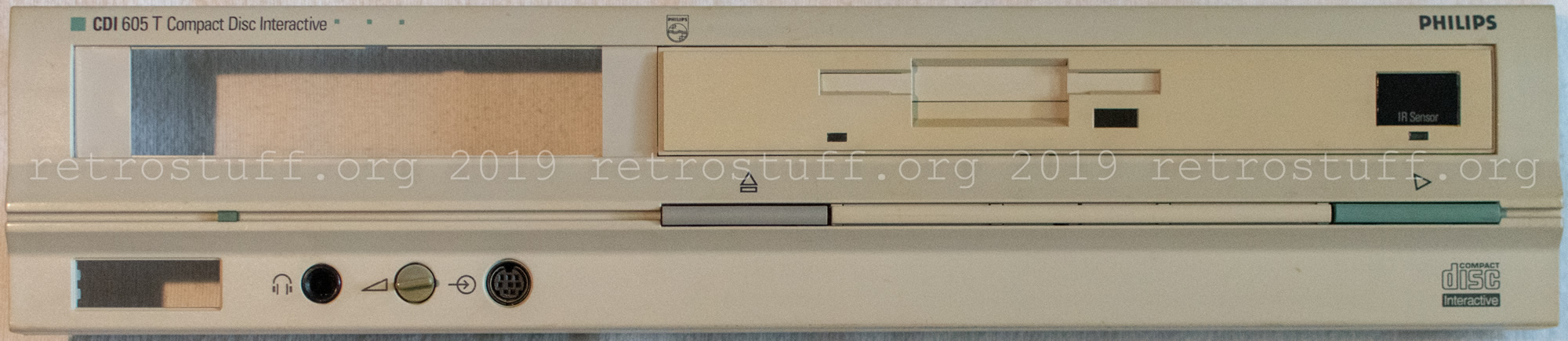
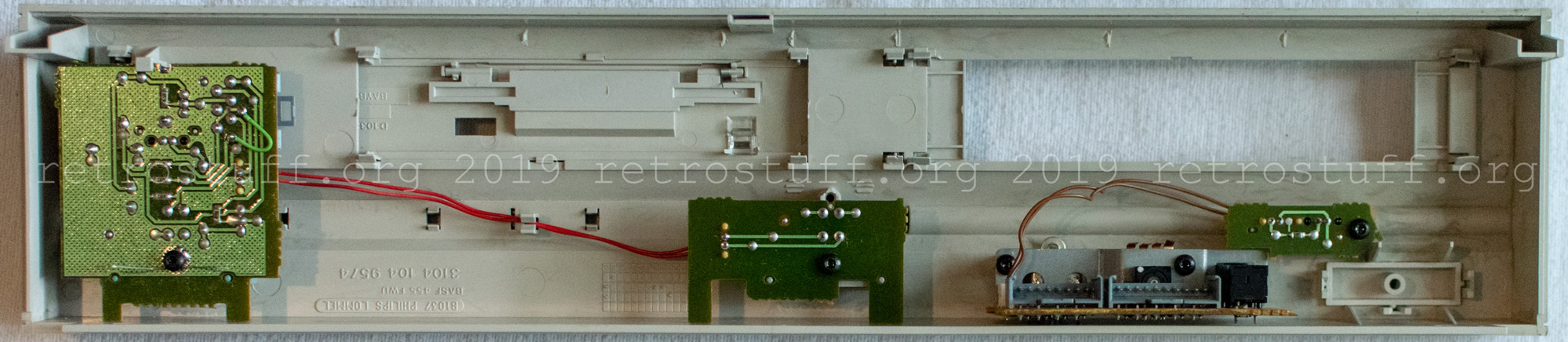
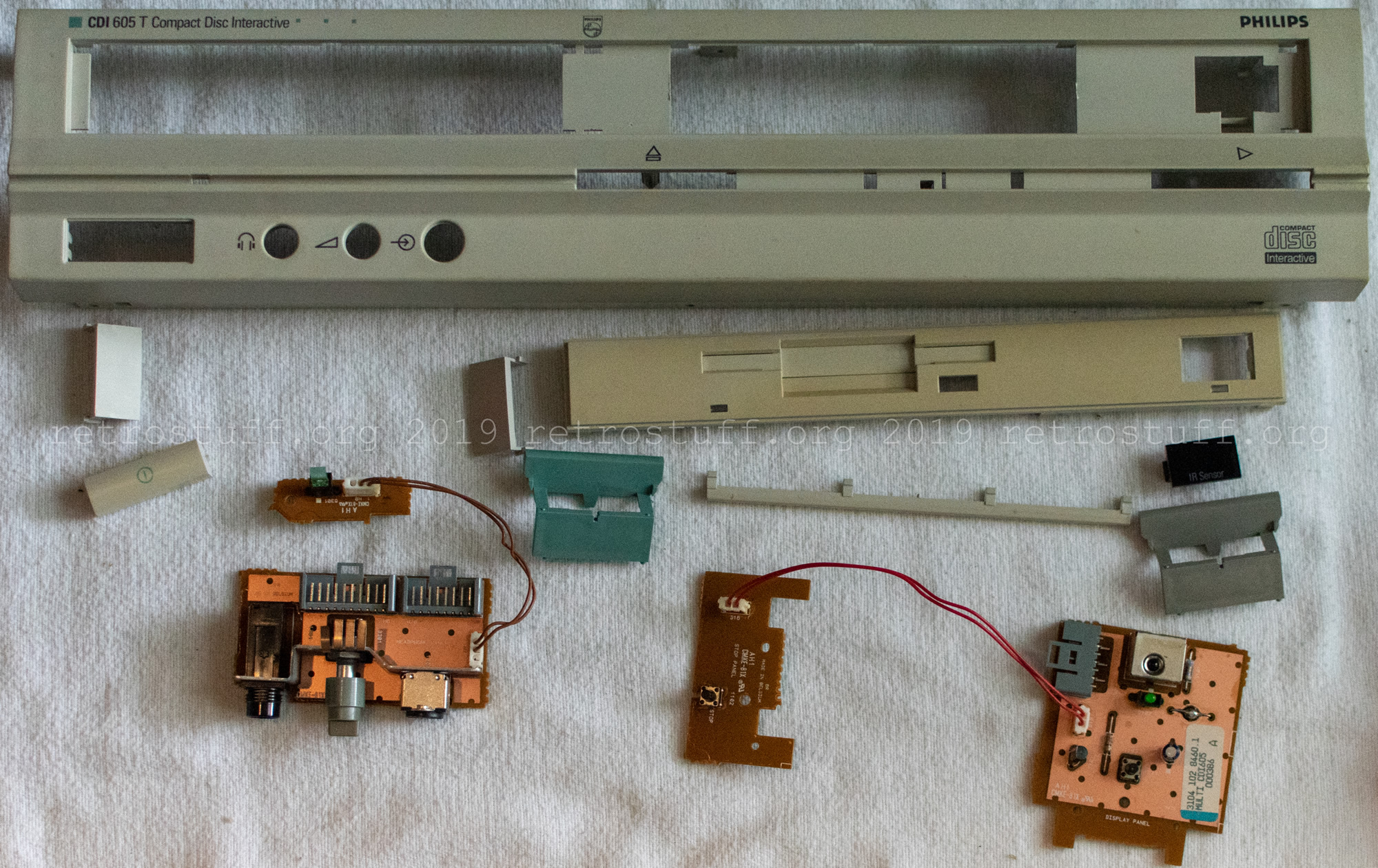
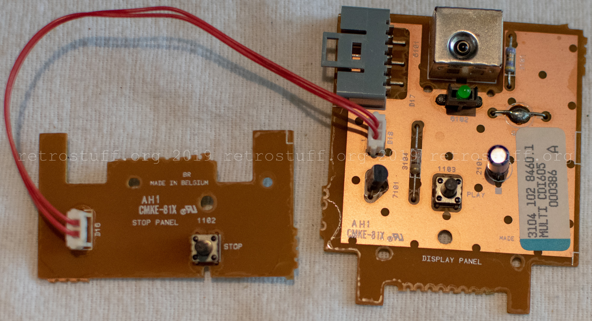
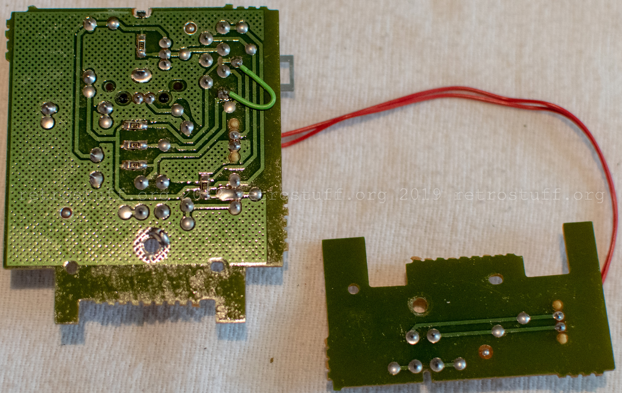
- This is the front panel. It contains a lot of plastic parts and also some PCBs. “Stop panel” is actually the eject button.
Close-up pictures – left side
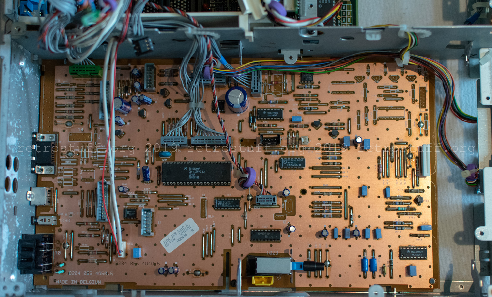
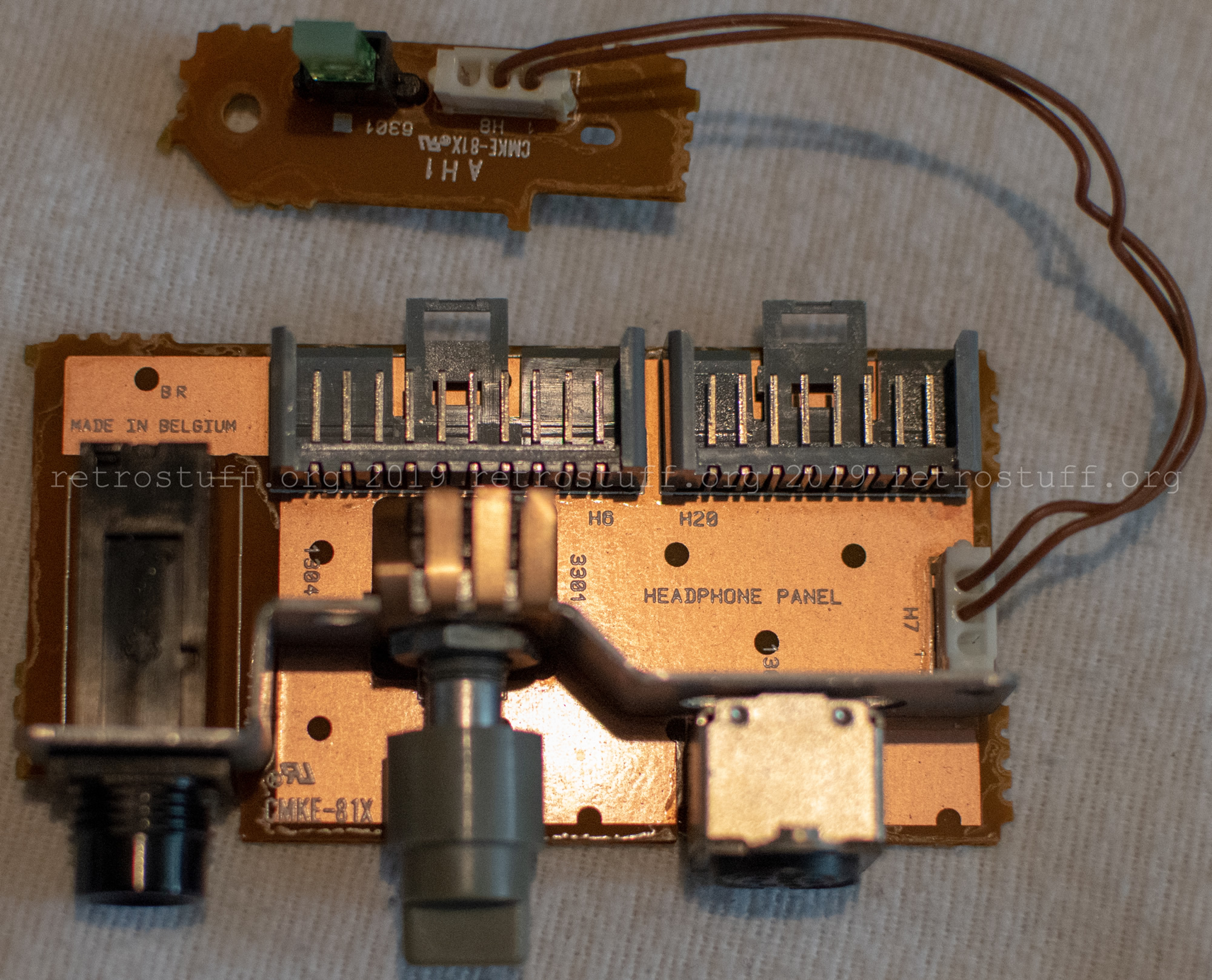
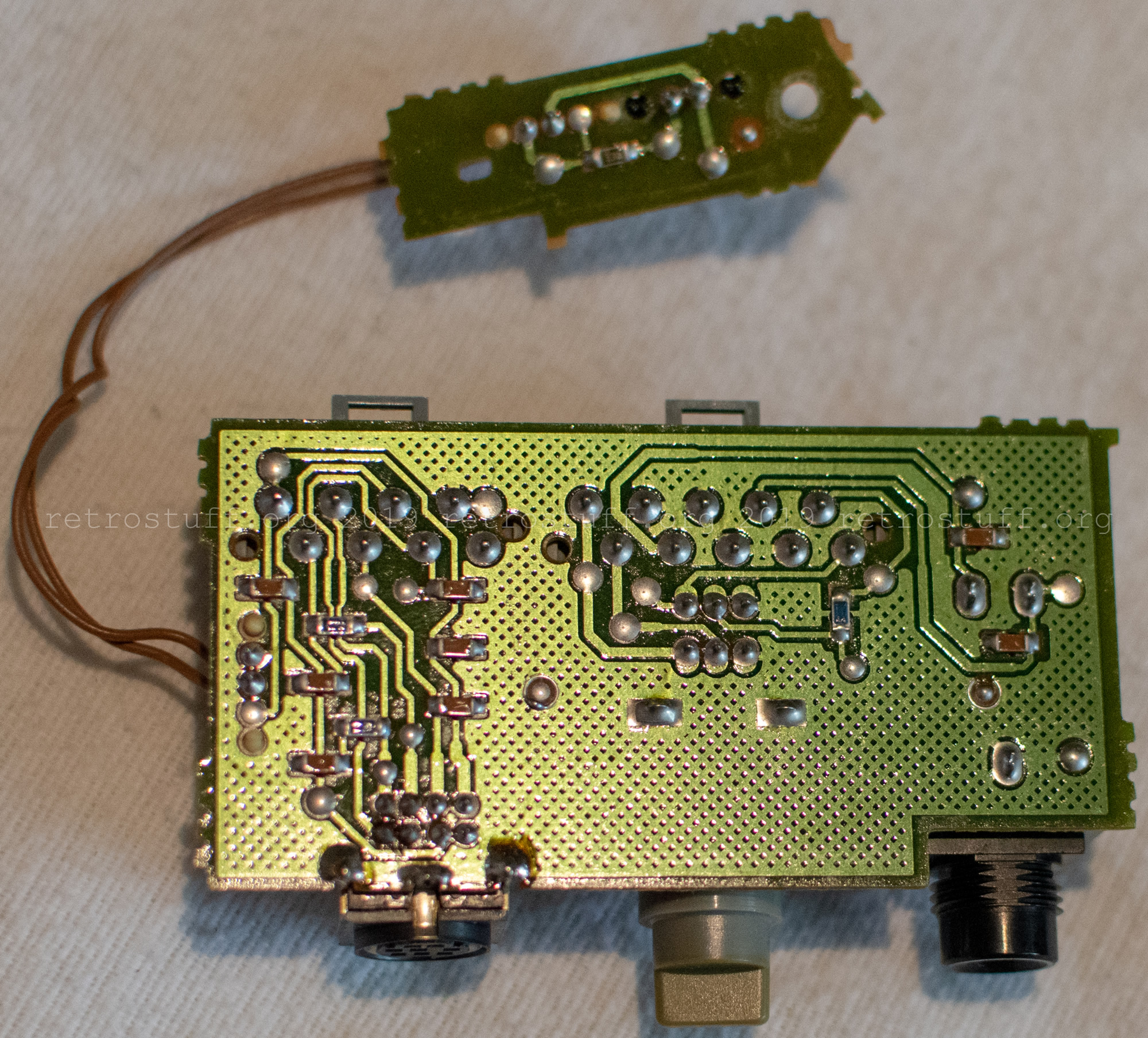
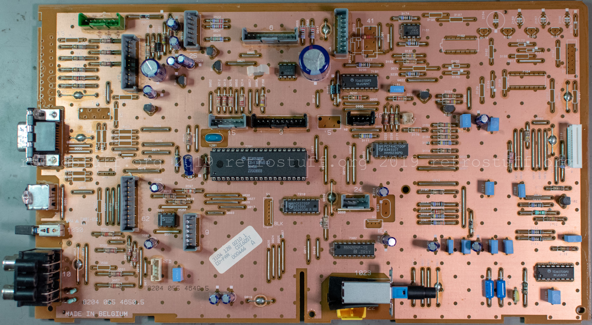
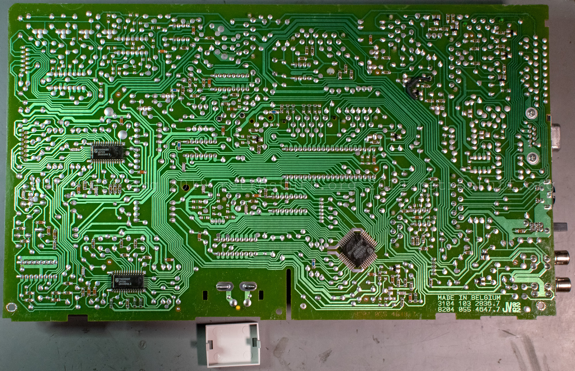
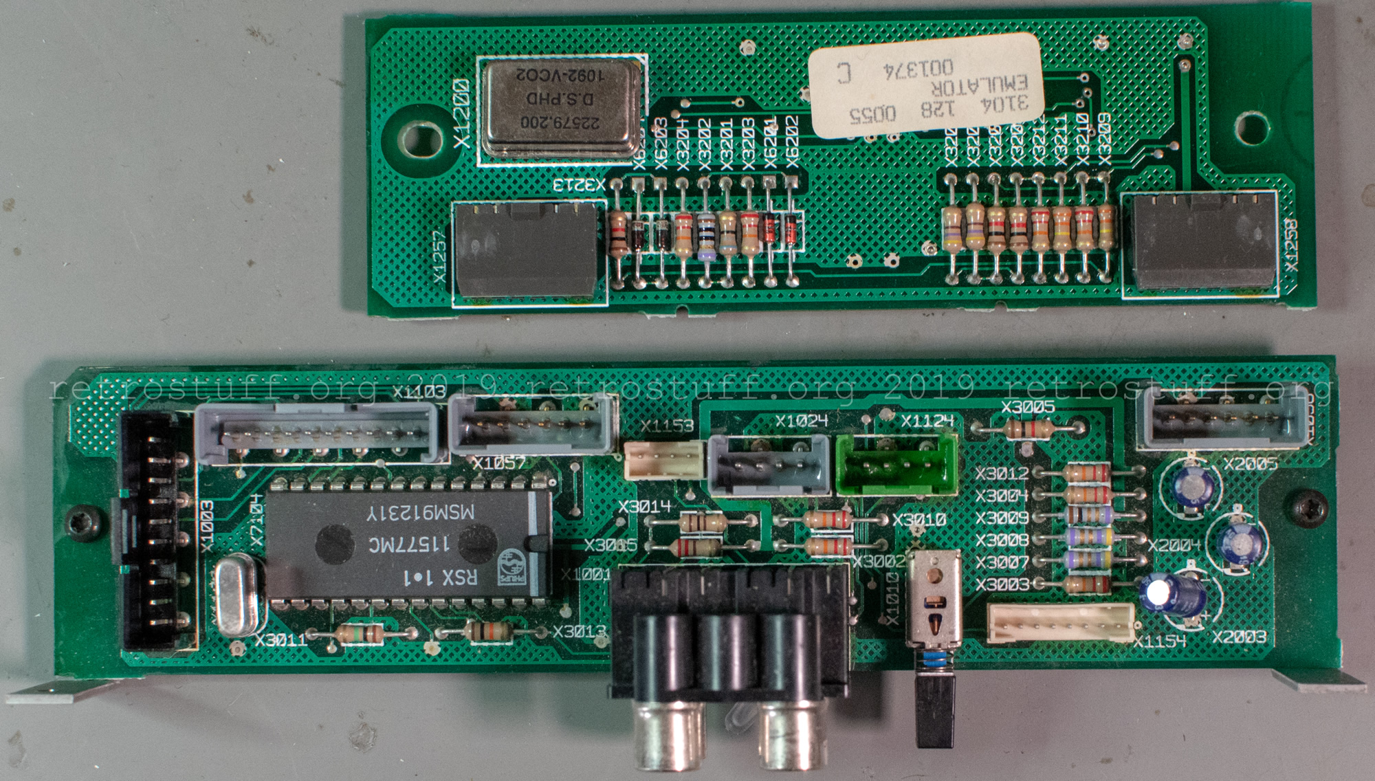
- The CD panel “CD-PAN” occupies the whole left side of the player. It controls all functions of the optical disc drive and has several sub-panels attached to it that feed the audio/video outputs, as well as the connectors for the external emulator. Additionally, it holds the main power switch, which is protected with a small plastic cap.
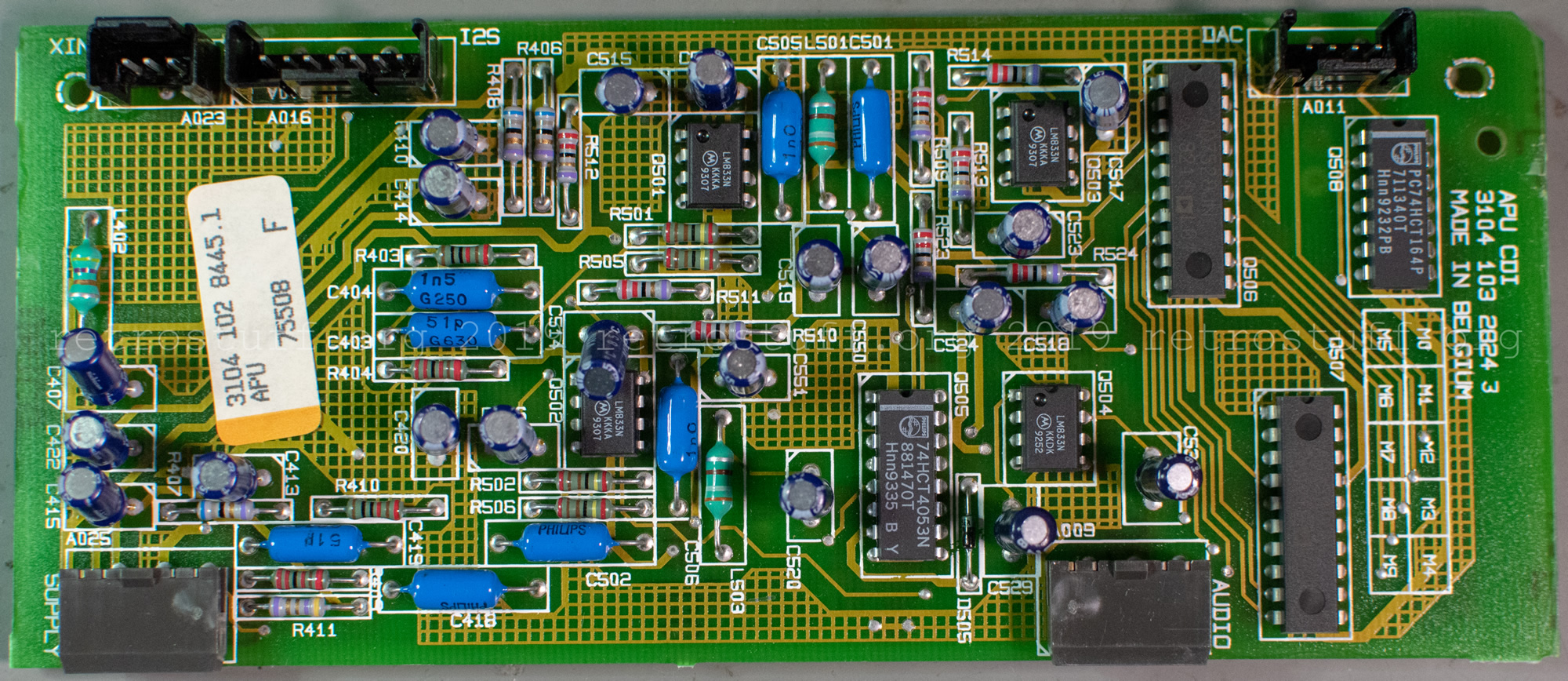
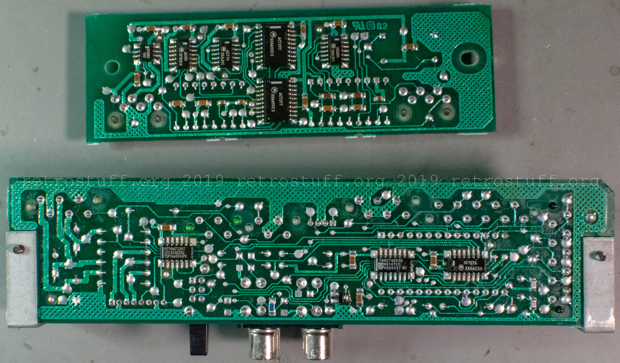
- APU panel (Audio Processing Unit).

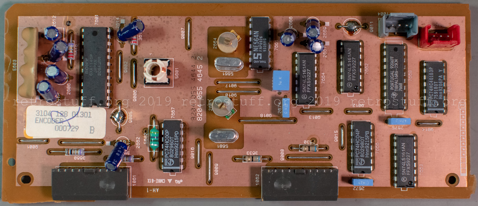
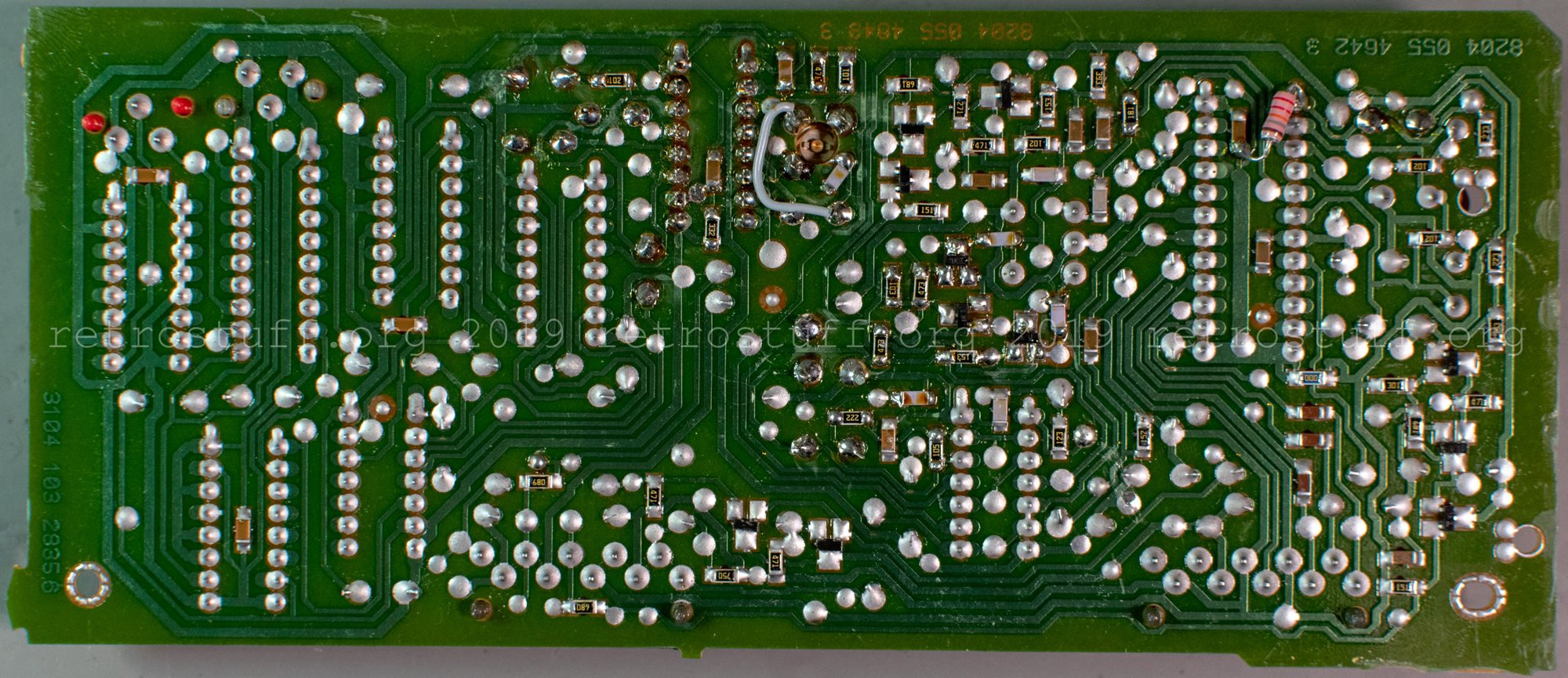
- Video ENCODER panel for both PAL and NTSC.
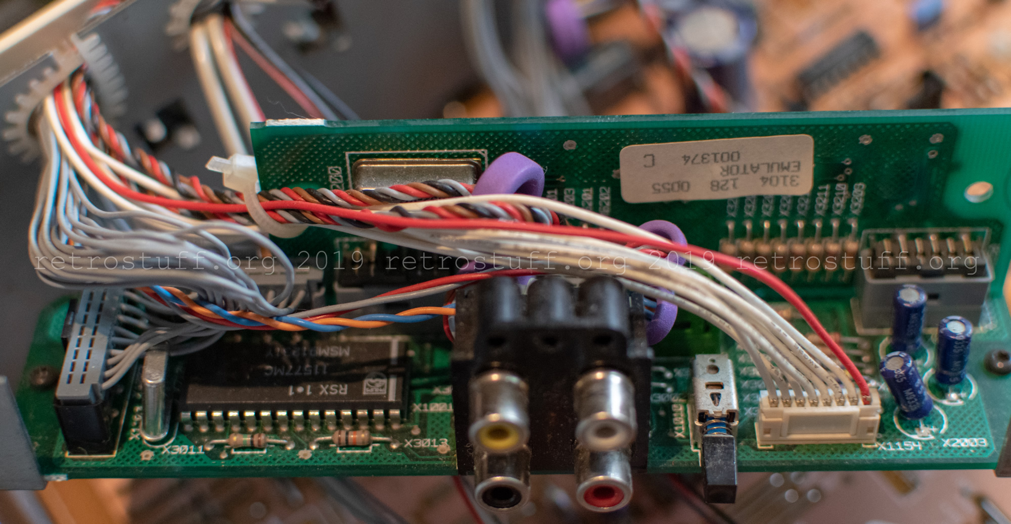
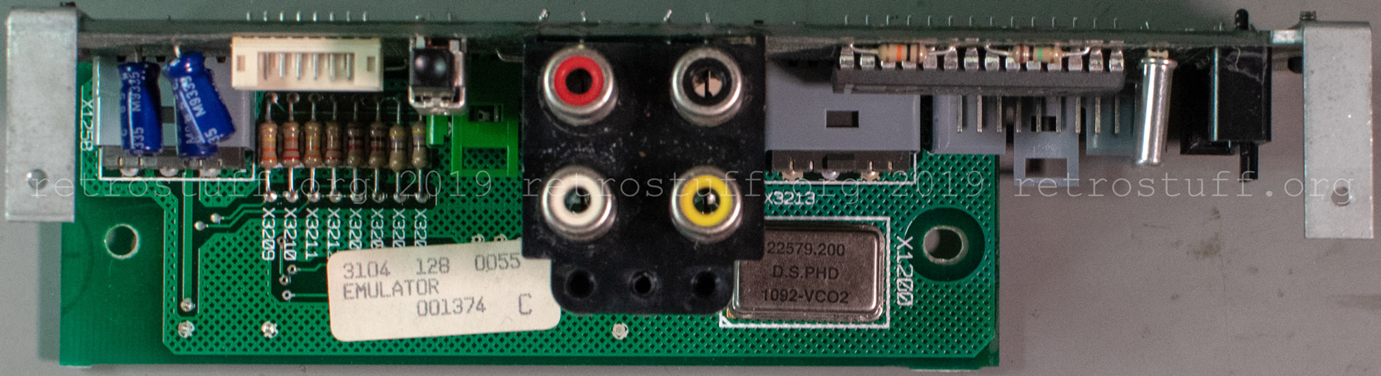
- The EMULATOR panel provides connectors for external CD emulators.
History
2019-08-07: Initial version published
2025-05-24: More details and repair notes for the ODD and DVC. Extensive changes and updates.
I have 2 CDIs – one can read disks, but I broke the CD tray off by accident. the controllers need fixing. would you fix one or both of them for me? i have no electronics experience.
Sorry, I don’t offer a repair service.