
When looking for a modification to improve the video size/quality of DVC games on my PAL CD-i player, I’ve found that only two tutorials are covering that kind of modification (here / here and here). The modification enables a PAL player to display full screen video without the black bars on top and bottom. NTSC players benefit from this modification too, as there are PAL exclusive software titles that already have full screen video (e.g. De Zaak van Sam) – without the modification, parts of the screen are cut off.
Unfortunately, the mainboard of my CD-i 220 differs from those used in the tutorials, so I had to get a service manual to figure it out myself. The service manual I found is valid for the Philips CD-i players CDI 220/20 220/25 220/39 (PAL) and CDI 220/31 220/37 (NTSC). It says there is an unimplemented switch 1201 in square C6 of the mainboard:

Next to it are two spots for 1k resistors that set the video output of the CD-i player. Resistor 3246 is for NTSC and 3243 is for PAL. According to the blueprints, the spots are on the bottom side of the mainboard:


Parts and equipment needed for the modification
- a 1kΩ resistor
- a SPDT (single pole, double throw) switch, DPDT is fine too
- a 3-way ribbon cable
- heat shrink tube
- a Torx T8 or T9 screw driver
- solder and a soldering iron
- a sharp knife and rotary tool to cut a hole in the front panel
Modification
Philips doesn’t use Phillips screws but Torx screws. A T8 or T9 screwdriver is fine to open the case. Note: I didn’t mark all screws in the pictures!
First, remove seven screws to open the outer shell and then six screws to remove the DVC slot. The DVC can stay in the slot.


When the DVC slot is gone, you have access to the mainboard. Next, remove the connector to the power supply PCB (yellow circle). The thing in the red circle is a ghetto repair of the infamous Timekeeper chip. At least it keeps the settings/high scores again, but the clock stops when the player is turned off – I’ll have to look into that sometime.
The yellow circle in the right picture marks the target area (C6).


Next, remove eight screws from the backside and four screws / three connectors from the front panel.
Pay attention when working with the disc drive: First remove two screws and then pull out the tray until two holes align above two more screws. Remove them and carefully lift the disc drive which is attached with three connectors to the mainboard. One connector is a very fragile flex cable.


The mainboard is secured with two screws. Take them out and you can finally have a look underneath it.
This is a close-up of the target area. Remove resistor 3243 (marked with a red X):

Solder the ribbon cable to the spots shown (+5V, * and ground). You can also solder them on the top side of the mainboard – just follow the * point and use any +5V and ground point available.

Now connect the mainboard to PSU, disc drive and front panel to test your modification. When the player is turned off, connect * with a 1k resistor to +5V, then start up a DVC enabled game and check if the black bars are gone. Turn off the player, connect * with the 1k resistor to ground and check if the black bars are there again.
Place the switch
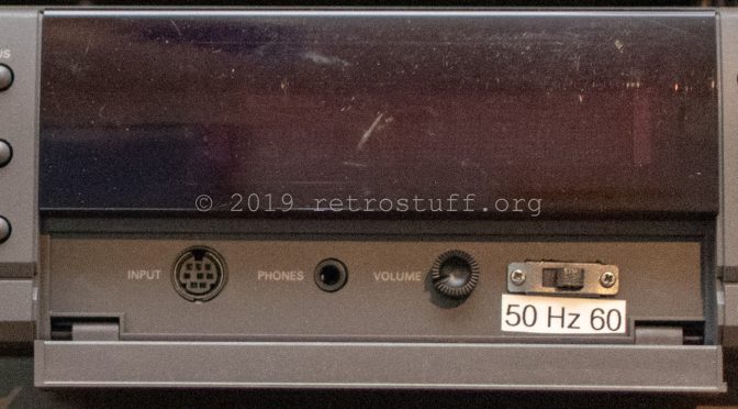
When everything works as expected then disassemble the front panel to find a place for the 50/60 Hz switch. The display PCB is held by seven screws and the input/phones/volume knob PCB by two screws. Be careful when assembling it later. Don’t put screws into the two holes marked with red circles – you could possibly damage the display!
I have marked a place to cut out the hole for the switch on the right picture.


A good place for the switch is behind the small front panel door. As there is limited space, I had to cut off some plastic of the switch until the door would close again. When it fits then solder the 1k resistor to the middle pole, * to the resistor and +5V/ground to poles left and right. Optional: Isolate resistor and cables with heat shrink tube.


Check again if the switch works and then assemble everything.
Done – you can now enjoy full screen DVC games as they were intended to be!
Hey. Do you have an entire diagram of the CD-i?
Hey, Yes, I’ve got the entire service manual for the models mentioned above.
Could you by any chance mail it to me or give a link? 🙂
My model is a 210/20, but the differences can’t be too big, right?
Unfortunately I can’t help you. It’s a printed manual and I haven’t found a digital copy yet.
According to this list the 210/20 has the same mainboard as the 220/40. The other two tutorials mentioned above should be ok for your model.
Okay 🙂 What I needed the manual for isn’t for this modification.
Do you know how many volts the power supply output to the mainboard?
This is the diagram of the power supply, hope that helps: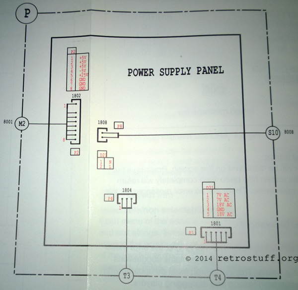
Thanks a lot! 🙂 That really helped. Seems like my CD-i’s power supply is broken. All pins show correct voltage, except for pin 5. It shows 0 instead of 25v.
Do you know how I could go about repairing or replacing the power supply? 😉
All I can tell you is to look for broken components and to replace them.
Maybe it’s easier to buy another 210 for replacement parts, it’s the basic model and very cheap.
Well, I would love to just buy another one, but it’s nearly impossible to find CD-i’s around here. This one is the first I’ve seen in my life…
Do you know if any other old Philips products (maybe VCRs) use the same power supply? 🙂
Don’t know about other Philips products, but I’m pretty sure it’s a custom module for this CDI player.
Have a look at ebay.nl or .de, the 210 is very cheap there. Maybe a seller is willing to send you just the power module – this should keep the shipping costs low.
I’ll take a look 😉 Thank you very much for your help 😀
You’re welcome! 🙂
Awesome mod! Works like a charm on my 210! 🙂
On another note, I have a 220 here which has one curious issue – the “open”-button doesn’t work properly!
If you press the button (at any time) it will not open the tray – the belt has been replaced, so it’s not the problem. BUT, if you manage to open the tray (e.g. with the casing open), the button will actually CLOSE the tray when pressed.
Any idea what’s wrong here?
Thanks, good to hear! 🙂
Sounds like a sensor or logic issue to me.
Some things you can check:
– When you gently pull the closed tray out for about 1cm (e.g. with the help of a screwdriver) it should continue to open by itself (It’s the same behaviour as when the Eject button is pressed.)
– When you have the case open check the wires and and connectors from and to the CD drive.
I’ll post instructions on how to start the built-in self-test routines at a later time…
Hi rosewood!
Yep, pulling out the tray (or pushing it, when the casing is off) will have the result you described.
Checking the cables between the drive and the main-pcb… no difference!
Except for the eject the console is working properly. No other issues.
I’ve added instructions for testing the front panel buttons here.
When the test confirms that all buttons work as intended then open the drive tray by hand.
Push the button to let the tray close just a little bit, imediately push the button again and see if it opens again. If it does then repeat opening and closing the tray with the button. Let it move in a little further each time until you find the position where it gets stuck.
OK. Next round!
I open the tray by pushing it a little from behind (with the casing removed). It opens automatically without any slowing down. If I press the OPEN-button during this phase it will (only) close.
Once opened, I can close the tray normally by pressing the OPEN-button. THE TRAY WILL NOT OPEN IF I PRESS THE BUTTON AGAIN!
Next thing – the self test. This does not seem to work on my unit as I have attempted it several times now. The player only starts up normally, no change on the display.
Is it possible that this is could be a promotional unit with a special firmware installed?
I remember a very similar behaviour on a car radio I bought some years ago on eBay. They had installed/activated a special firmware or function that would shut down (most of) the front panel’s buttons. Once you flashed it to a “standard” firmware it would function normally (again).
Now that you mentioned promotional unit, there is a lock function that is supposed to prevent you from opening the tray, to enable or disable it hold ‘STOP’ when turning on the player. I haven’t thought of it because on my player it only hides the ‘open’ command on the screen, the button still works.
That fixed it. 🙂
Well, and it explains a lot. Because the 220 still contained a demonstration disc + the original cdi-advert-sticker was still on the display.
Most likely a demonstration unit of sorts.
Anyway, thank you for your help! 🙂
Hi,
Is there any info or specs for the little belt that drives the cd tray in and out?
Great info! Thanks!
The part number for the belt in CDI220/20 is 4822 358 31168. A rubber band found in the kitchen does the job as good as the original belt though.
Please. Help me.
Do you have the mainboard and servo circuit diagrams of philips cdi 220?
The CDI220 was built with five different mainboard layouts – which revision are you having trouble with?
Thank you for your answer.
Friend, my version is CDI 220/77.
Sorry, I don’t have circuit diagrams for that revision.
220/77 is the US variant of 220/60 and similar to 210/40, maybe this will help you: http://www.cdiemu.org/?body=hw%2fcdi210sw
Thanks for your help! May God blesses you!
Dear Friend, maybe you could help me.
Do you know if the tension from mainboard that feeds the optical pick-up unit doing it to emit laser light is +5v? (Optical Unit is CDM12.4)
This is the connection for CDM12.1, hope that helps:
https://retrostuff.org/wp-content/uploads/2015/10/cdi_cdm121.jpg
Thank you!
It is exactly what I need. Well, let’s work 🙂
The digital service manuals for many Philips players (unfortunately not the 210/20) are now available at the ICDIA website.
They are here: http://www.icdia.co.uk/svcmanuals/index.html
Hi if I wanted to make my PAL CDi just NTSC and not install the switch could I take the existing resister from 3243 and solder it onto 3246?
Hi, Yes, you can move the resistor from 3243 to 3246 to change it from PAL 50Hz to 60Hz. It won’t output true NTSC though. To accomplish that you’ll also have to replace crystal oscillator 5240. PAL: CXO-046B 30.000 MHz, NTSC: 30.2098 MHz.
Ok thanks I appreciate the help. Ultimately I ordered a PAL Matchline PH220 and I’d like to play some games on it so I’ll just try the resistor method first.
Amazing tutorial! Was excitedly following it until a released mine is a 220/40 with a different PCB. The tutorials referenced at the start – the first is or 210 and the components are different. The 2nd tutorial link I can’t tell as all the images are blank (expired imageshack account I guess). Any ideas? Any help much appreciated, thank you.
Thanks. Take a look at the service manuals at ICDIA (http://www.icdia.co.uk/svcmanuals/index.html), yours is a CDI220 with Mono II mainboard. You should be able to follow the available tutorials and the schematics from the service manual. The PAL/NTSC differences are clearly marked.
Thank you for the reply rosewood! I’ve taken a look at the service manuals and there’s some interesting stuff. RGB output is entirely PAL only for example. However there’s no unimplemented parts designated NTSC/PAL – the regional differences seem to be pretty significant (am looking at the Analog Video Part Circuit diagrams). Y/C Luminance output both have the same resistors across PAL/NTSC but with different tolerances. Looking at the Y/C Chrominance output there is a single Resistor implemented only in PAL versions (3674) – maybe this is the one to remove?
You are mixing things up here, it is actually much easier than you think. Your goal is to switch the processor from 50 to 60 Hz and not to turn the whole unit from PAL into NTSC. The PAL/NTSC differences in the service manual can be used as hint on where to connect the switch. For your player it’s the same components as in my tutorial (move the resistor from 3243 to 3246 or install a switch).
Thank you rosewood. Located the area (Area D2 on the underside of the board for anyone else who’s looking for 3243/3246 on a CDi220/40) and found the resistor. Black bars all gone – it looks glorious 🙂
My Philips cdi 220 works fine with original vcd video and original cd audio. With recorded audio and game it does not work. Do my saved games work on another cdi player? Where is the problem?
There can be various causes, but mainly old/weak laser and more or less translucent CD-R, as discussed on Facebook.