
This is a new member of my Pippin collection: The Atmark Wireless Controller Set (BDE-82014 / PA-82014). It has the same functionality of the standard AppleJack controller, except that it is wireless. Three infrared LEDs send the signals to a receiver. The set is advertised as compatible with both Pippin Atmark and Macintosh computers. The latter require a P-ADB to ADB adapter and the AppleJack system extension (not included).
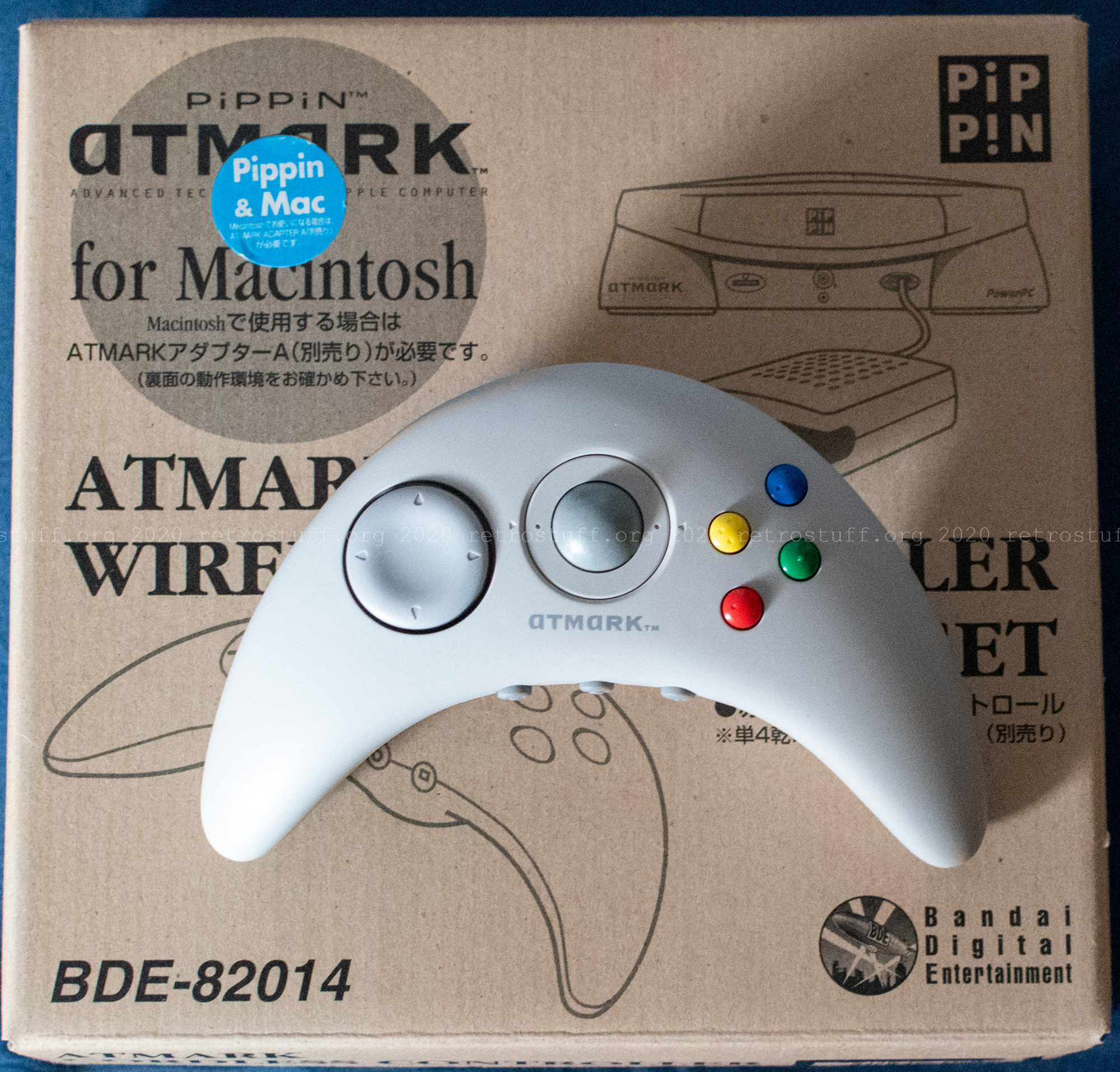
The set contains controller and receiver, as well as two leaflets: Instructions for the set and instructions for the Macintosh driver.

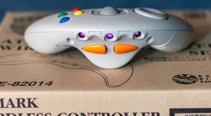
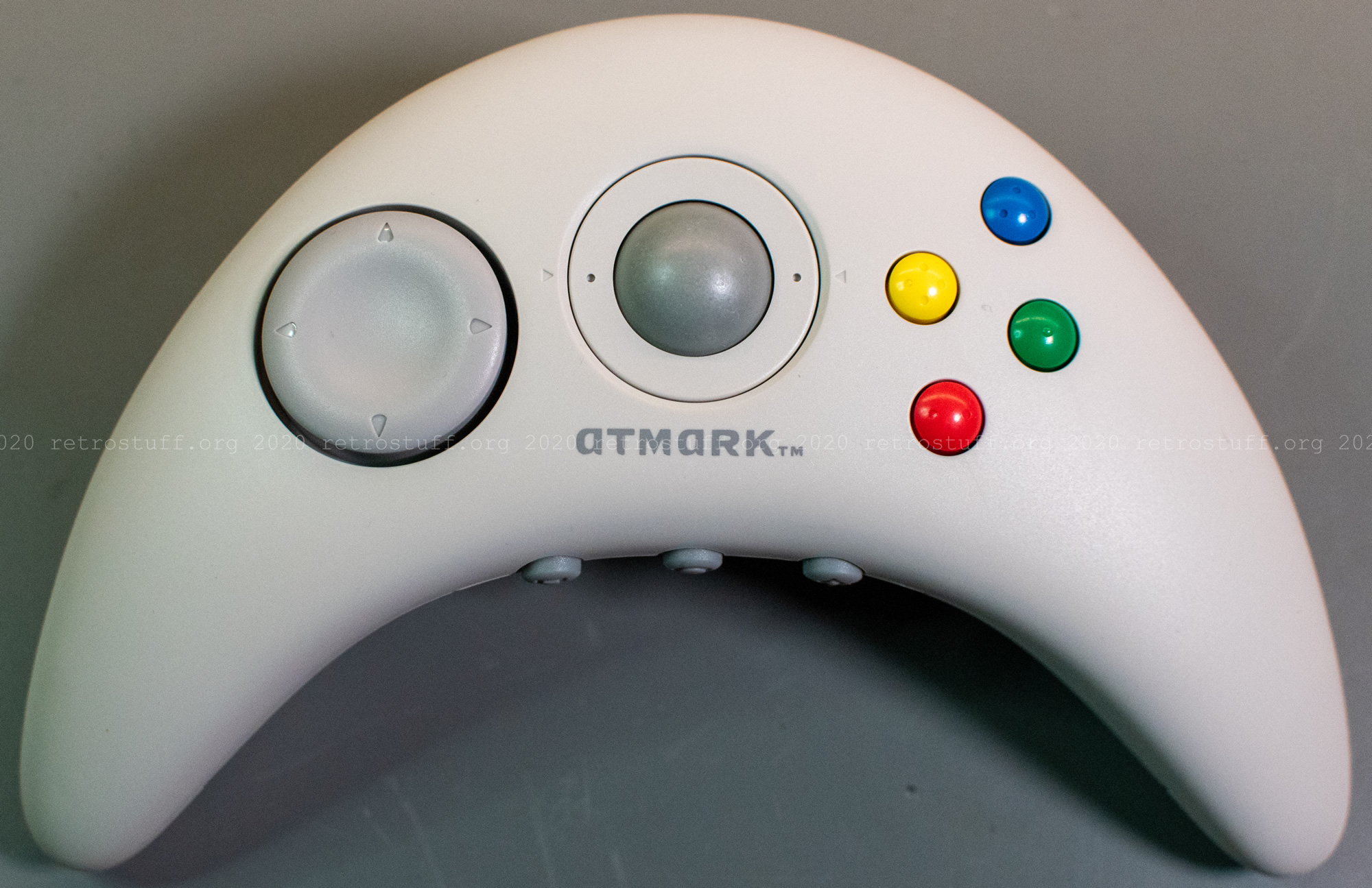
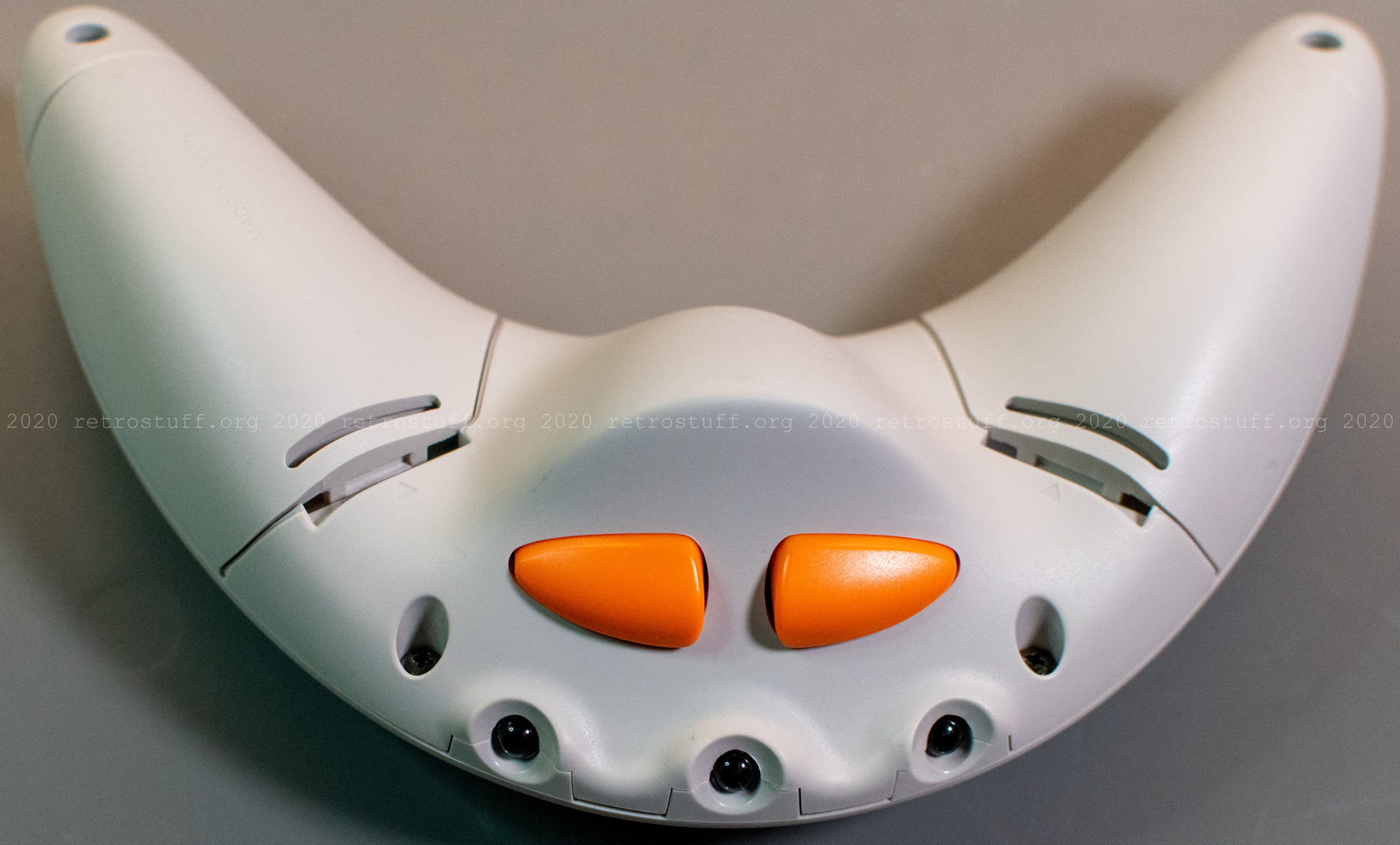
The wireless controller
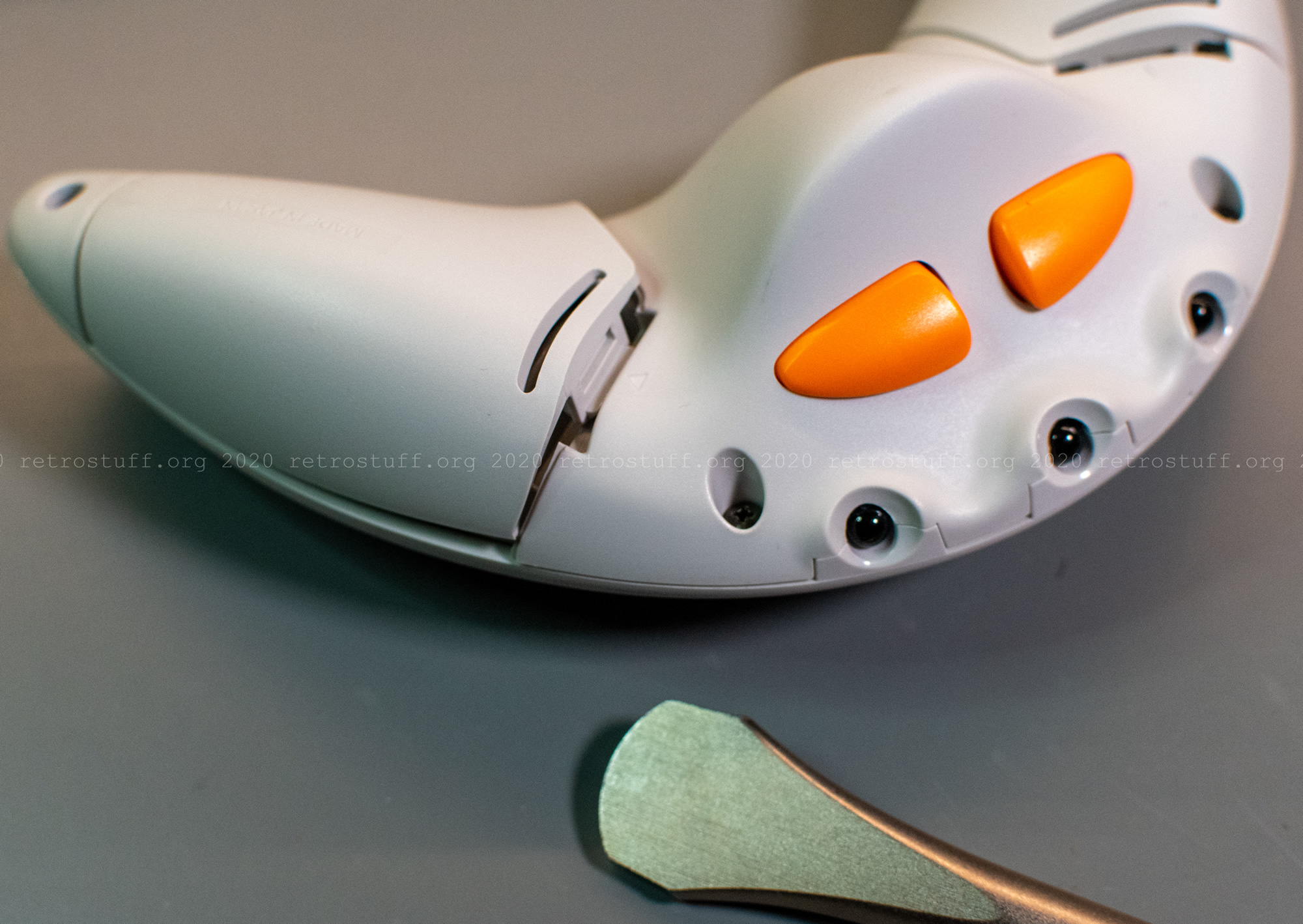
Let’s have a closer look at the controller:

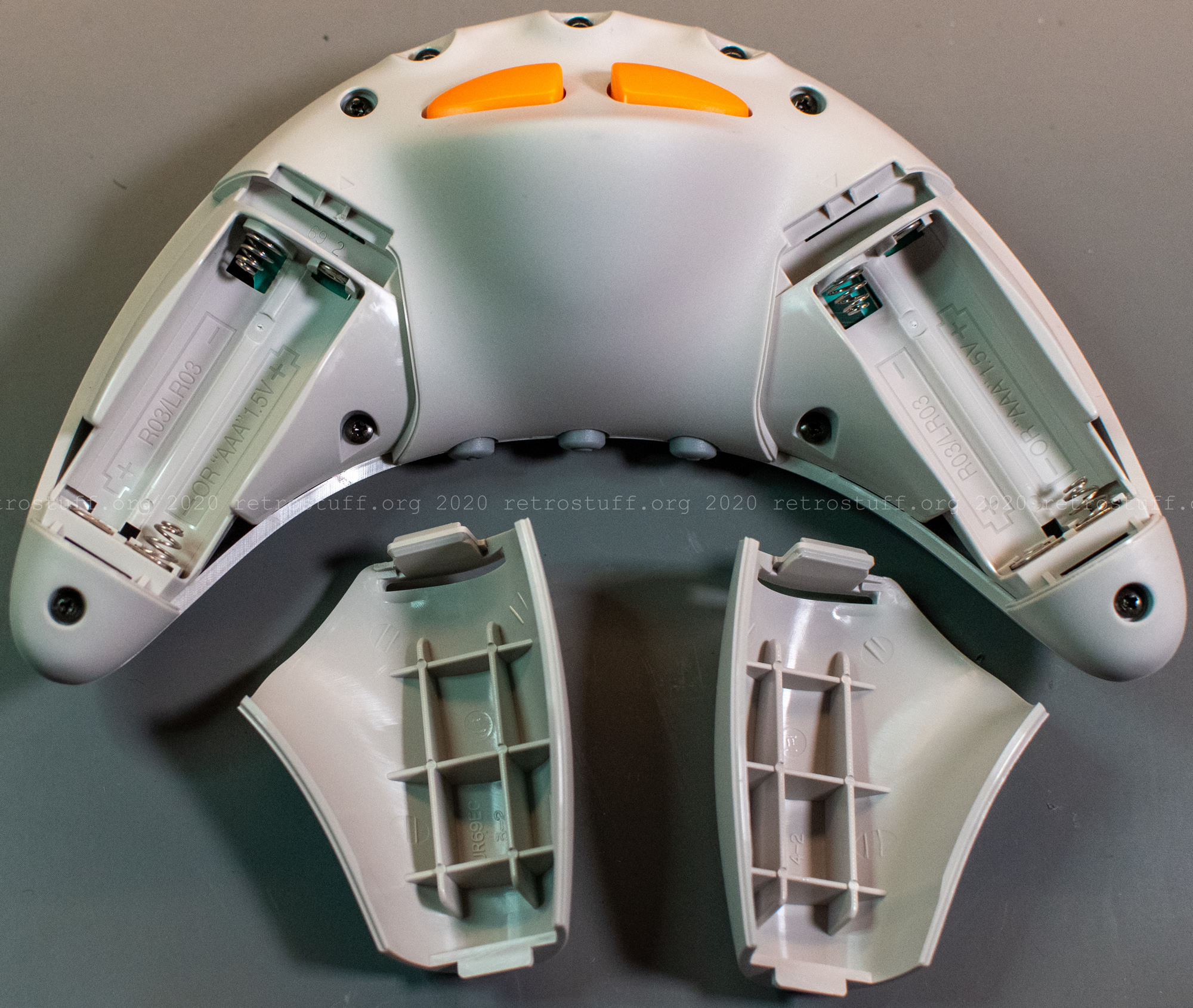
To open the battery compartments, you will need a coin. It is also recommended to close the compartments with the help of a coin because the tongues are rather stiff. If you don’t have a coin at hand, there is a screwdriver bit (Anex AHC-1511) available for these kind of operations.
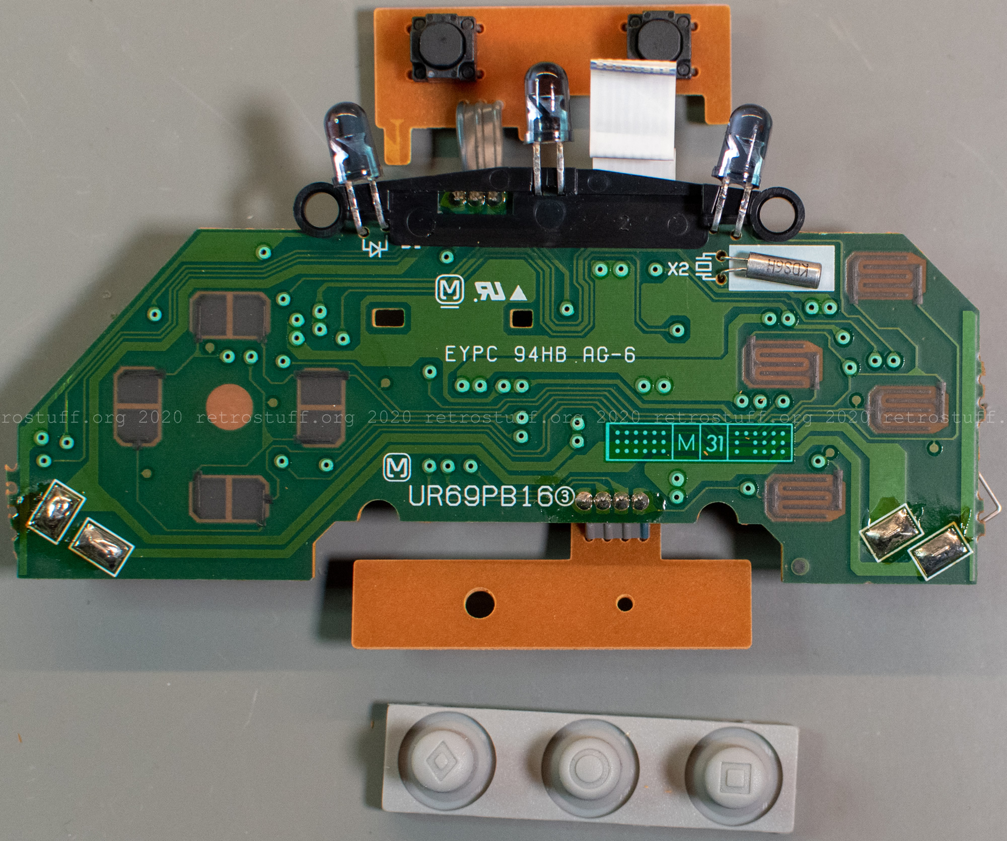
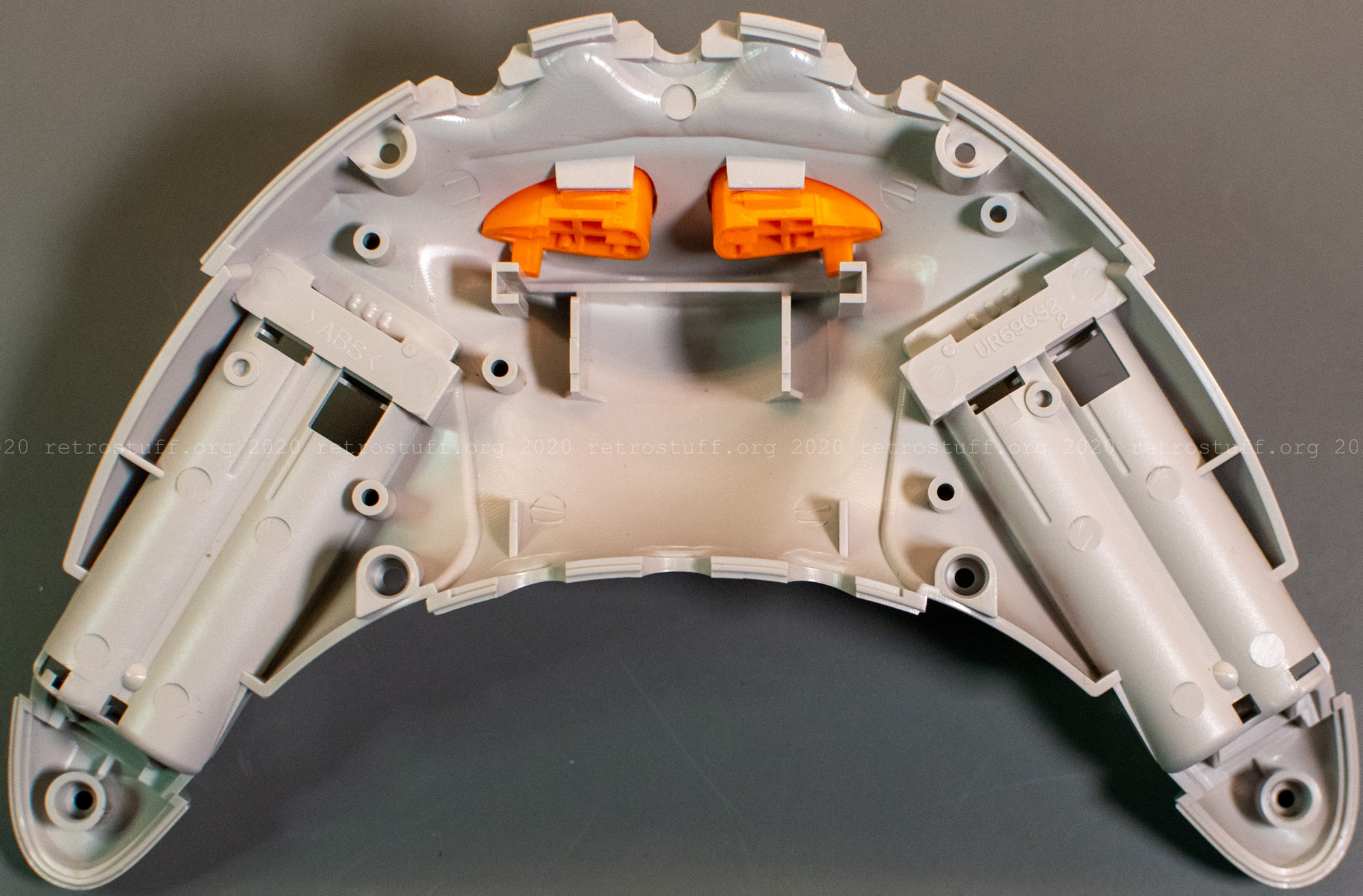
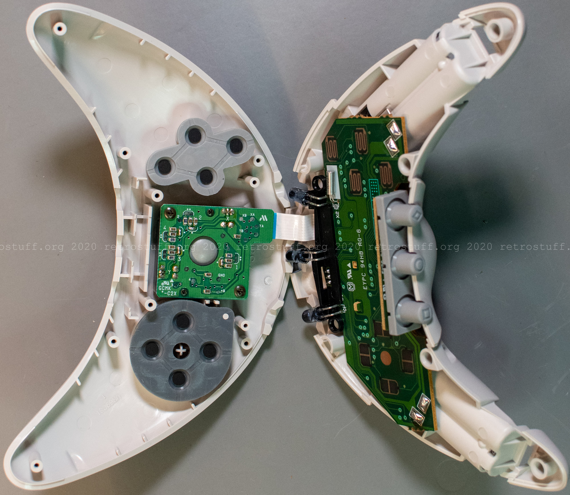
Unscrew six Phillips screws to disassemble the controller. Carefully pull the two halves apart, starting by the horns. Don’t rush it because the two PCBs are connected with a flexible flat cable. Then, pull the FFC from the trackball encoder PCB.
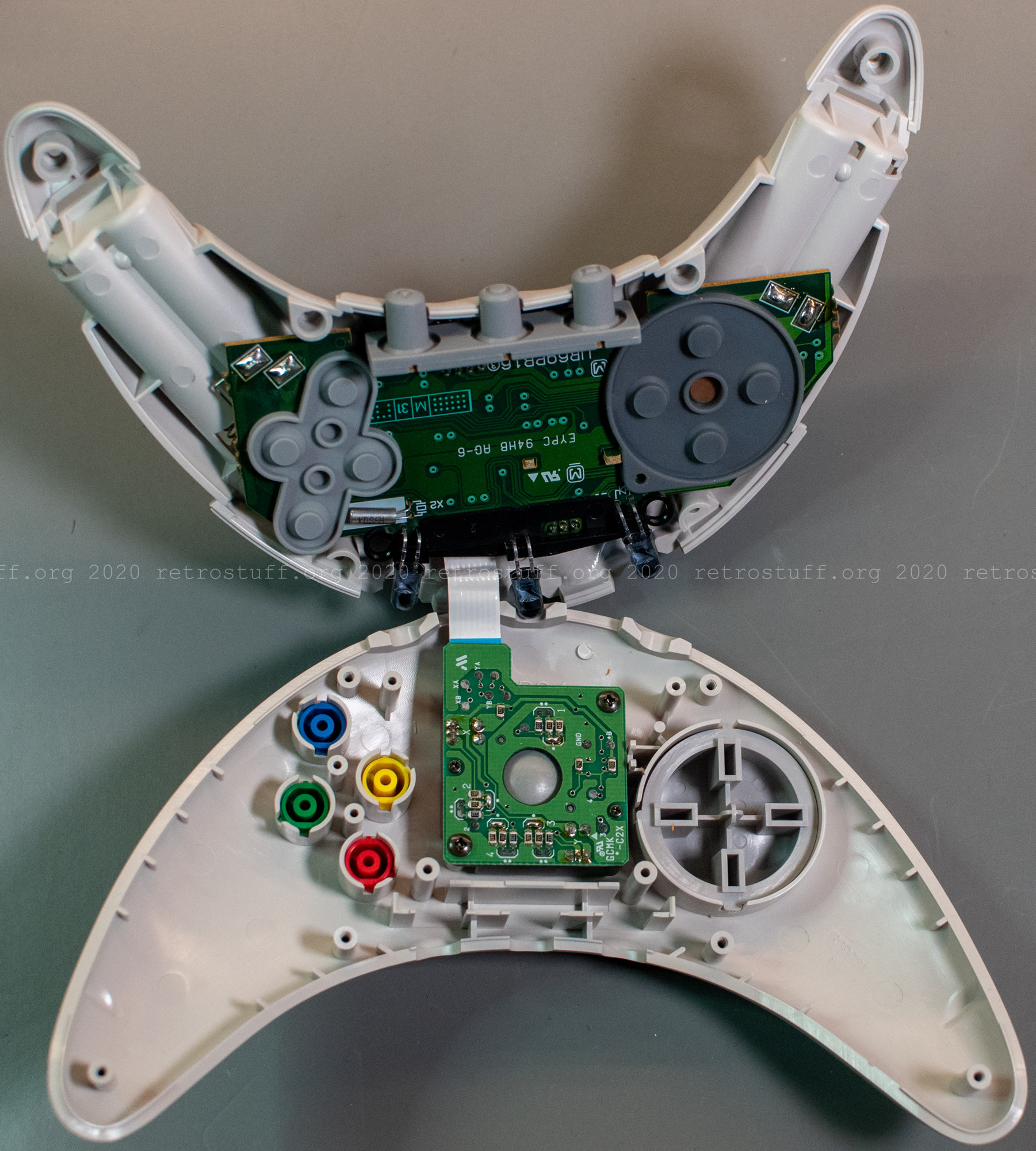
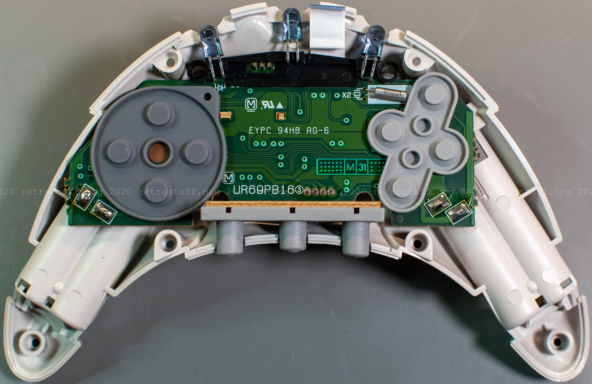
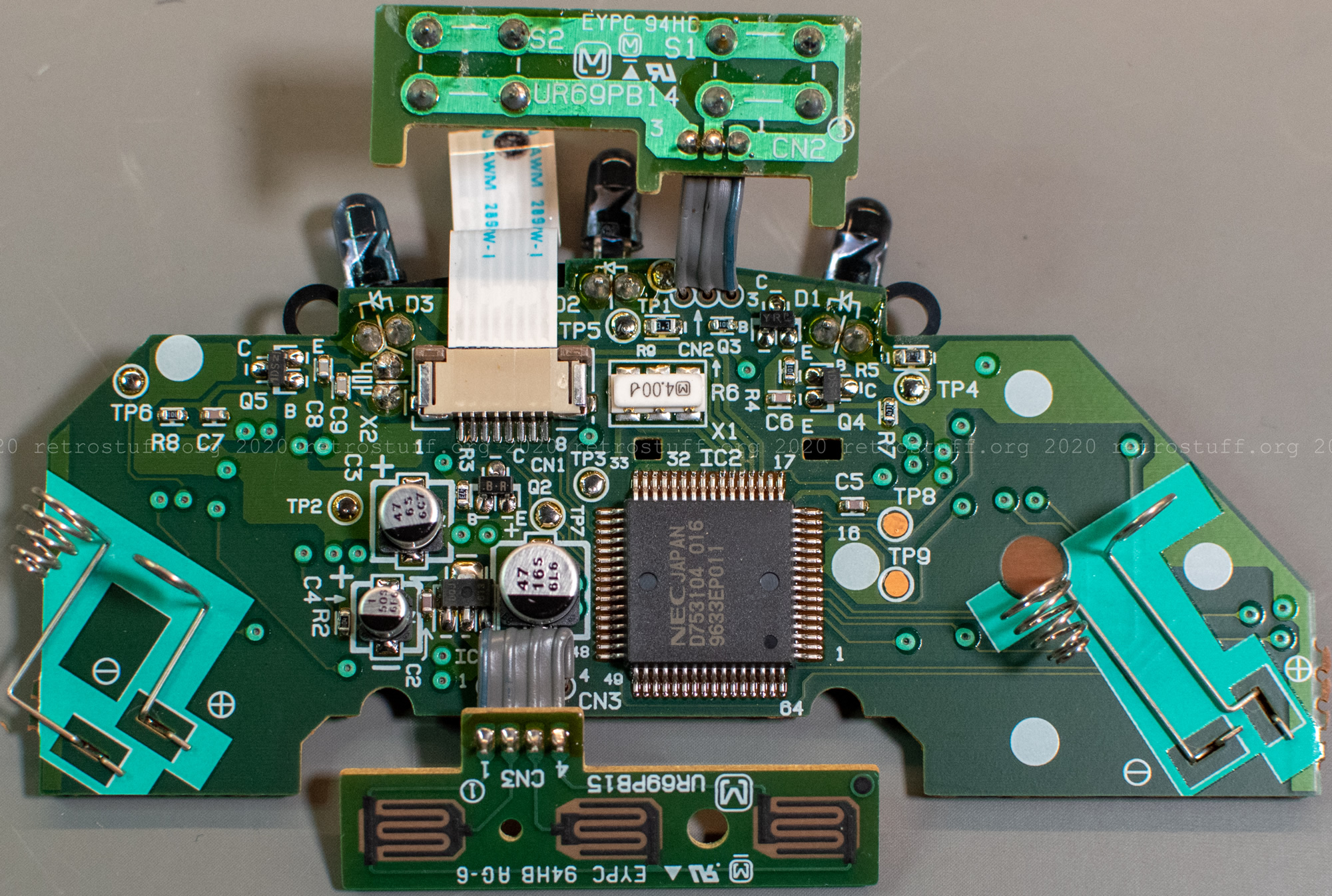
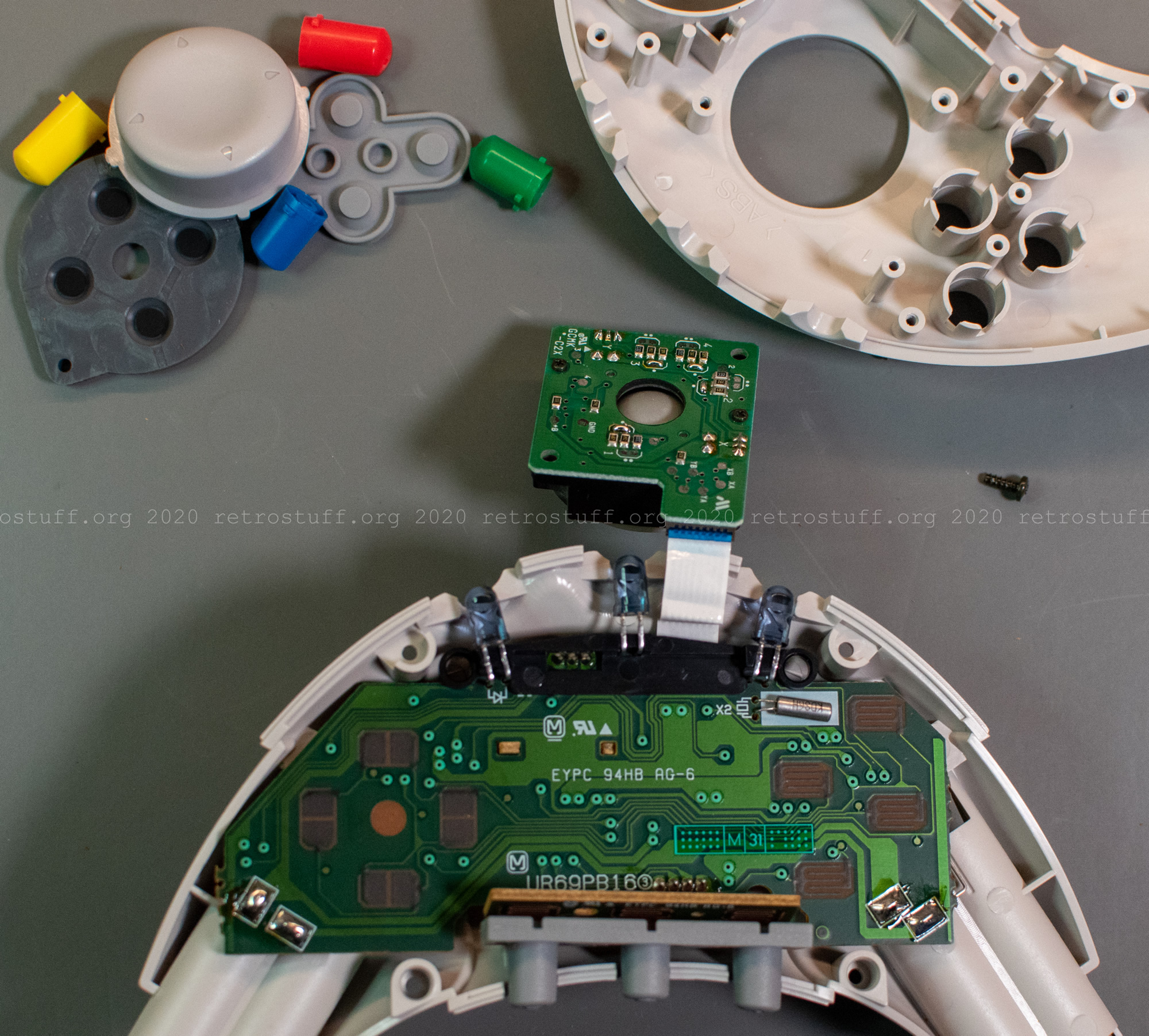
The insides don’t have a lot in common with the wired AppleJack controller. The most prominent component of the main PCB is a NEC µPD753104 microcontroller.
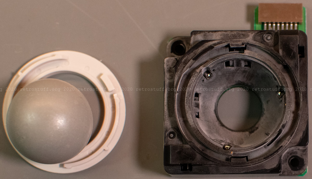
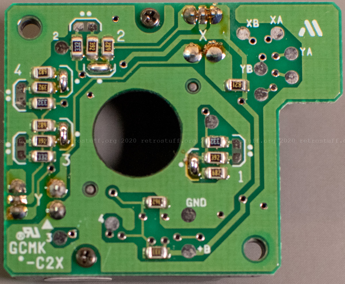
The trackball encoder unit, which gave me some trouble in the wired controller, is different as well. The whole unit can be removed from the inside and I was able to turn the plastic ring by hand.
To put everything back together, populate the lower half first. Then, populate the top half and hold the buttons with the rubber parts in place. Finally, attach the flat cable to the trackball encoder PCB and screw it back in place. The two halves are now ready to be put together again.
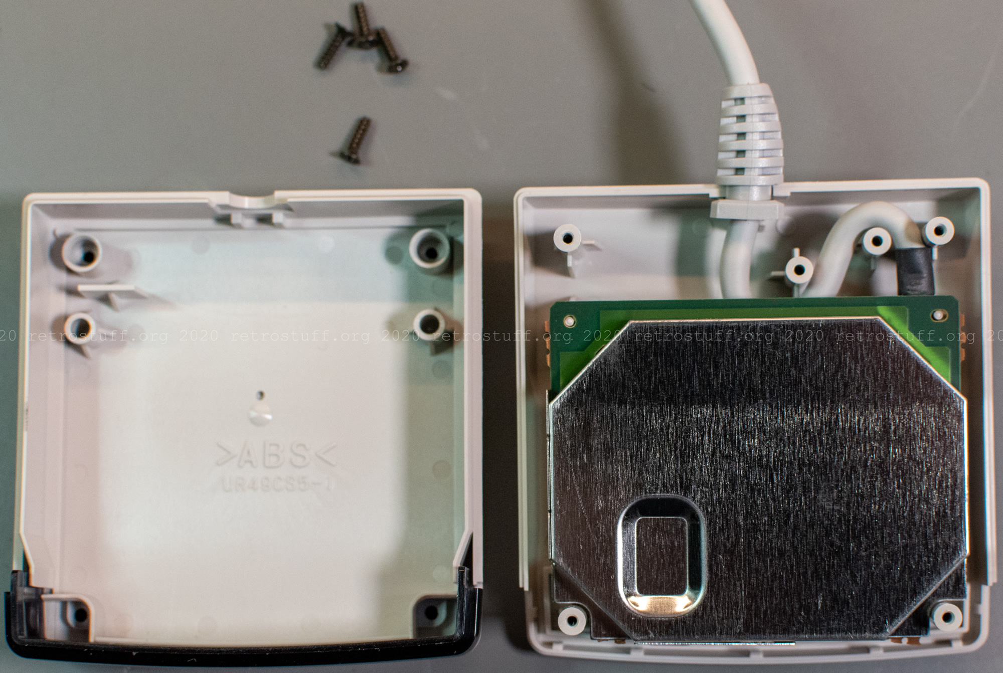
The wireless receiver
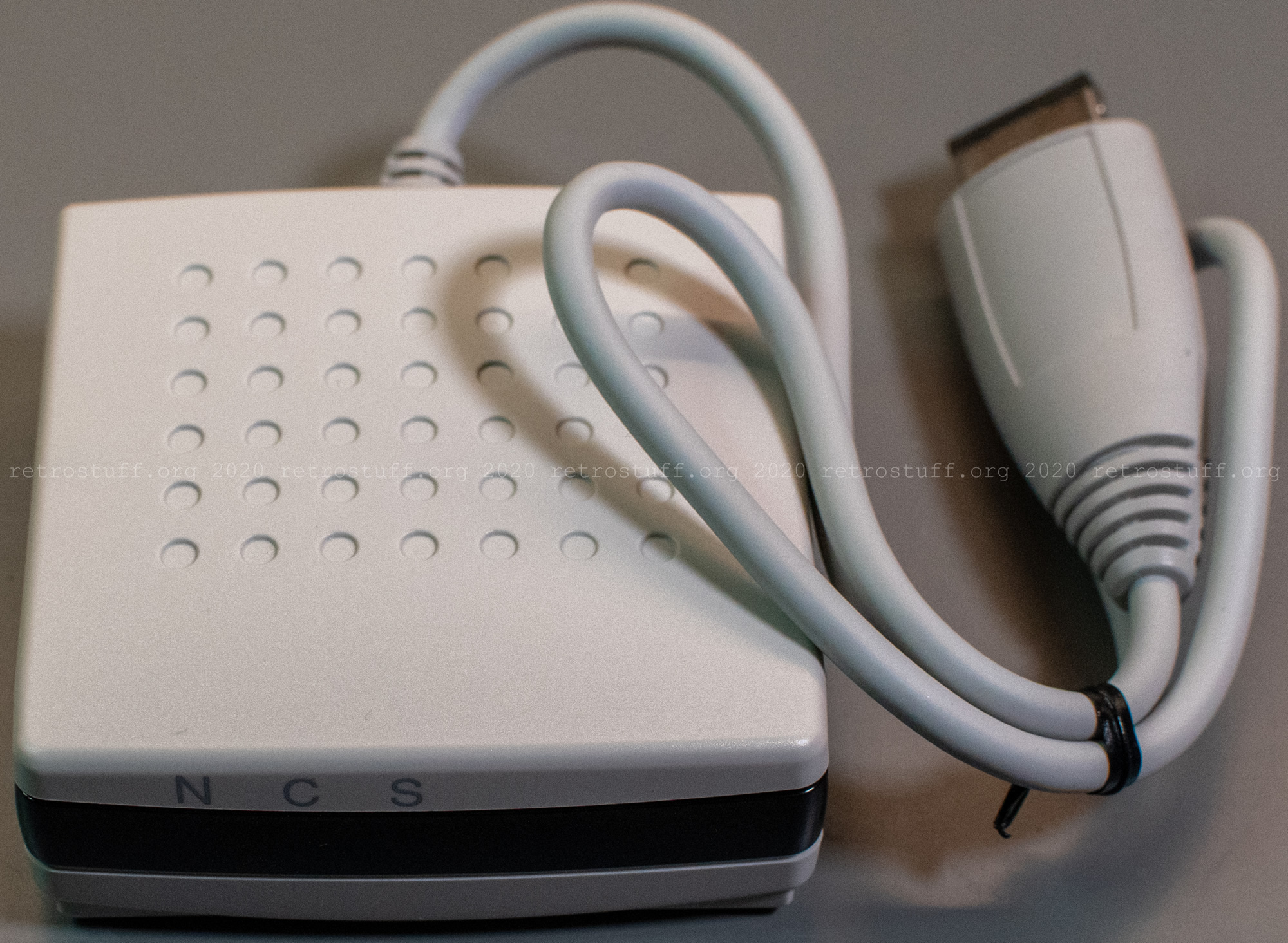
This is the receiver unit with the P-ADB connector. N, C and S are the names of the control LEDs. This is partially explained in the instruction leaflet.

Four Phillips screws are hidden underneath the rubber feet. Metal shields encapsulate most of the PCB.
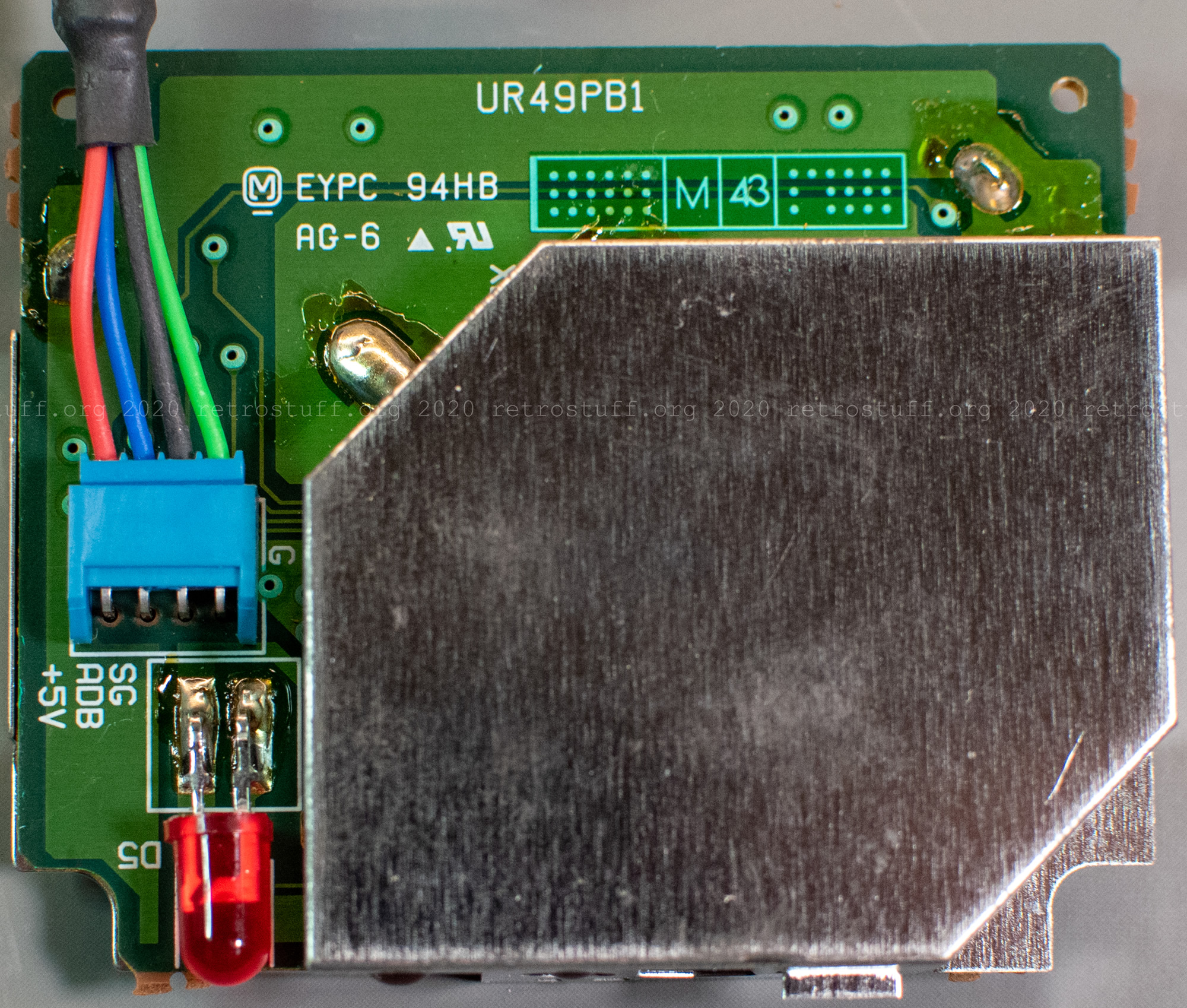

After carefully desoldering the metal shields and some cleaning up, we have access to the receiver PCB. The chips are a TFK U2505B IR receiver amplifier and two microcontrollers (Microchip PIC16C57-XT/SO and NEC µPD754304).
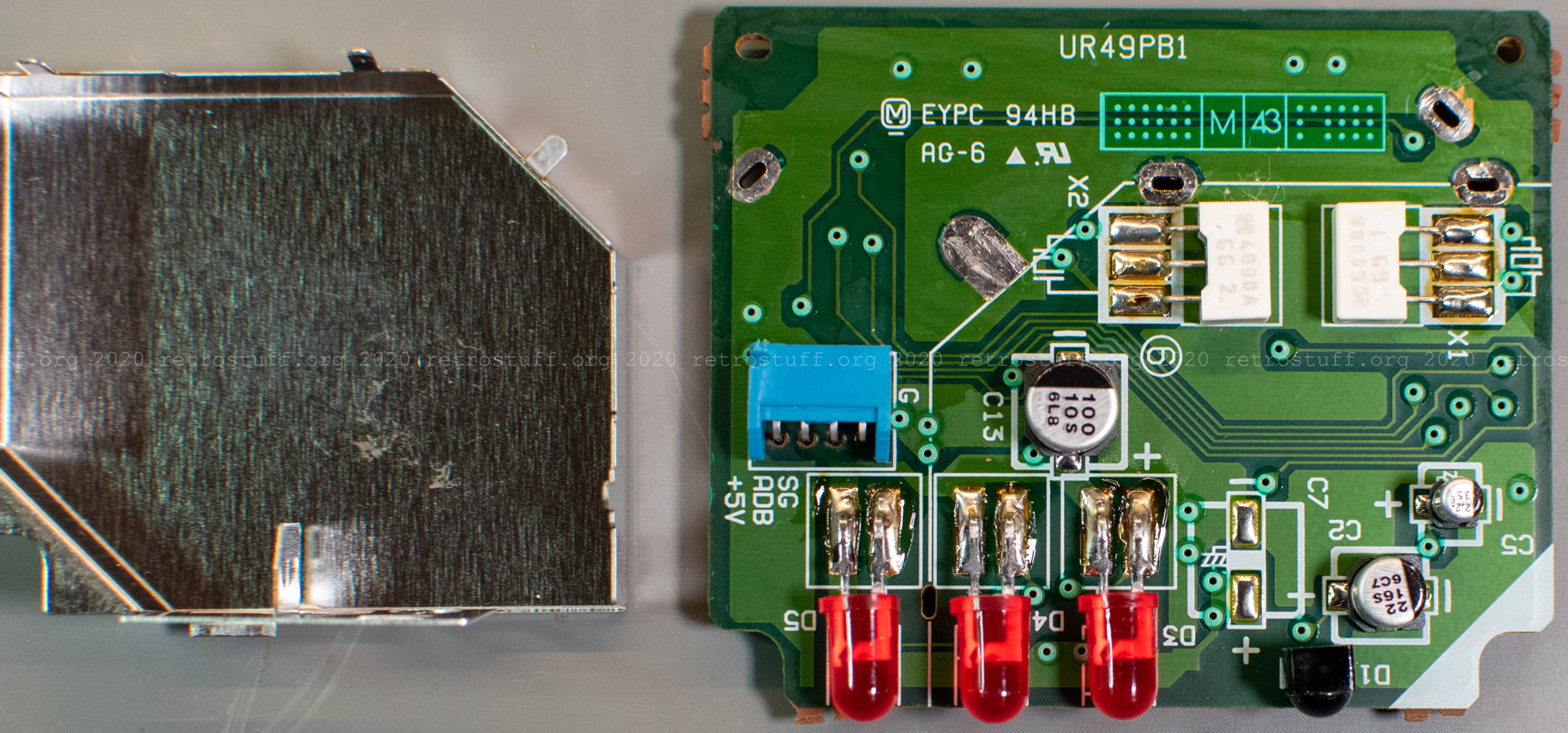

Apart from soldering the metal shields back in place, there are no special requirements for assembling the receiver unit.