
This guide shows the replacement of the laser sledge in Philips CDM 12.1T CD mechanisms. It assumes that you have already cleaned the lens and done the necessary troubleshooting to rule out other errors (see this article for diagnosis with the Service Shell). If you only get dirty disc messages or experience stuttering audio/video from time to time, you can still follow the guide to clean and grease the mechanism.
For documentation, I replaced the laser sledges of two CDI450 players with unreliable or no disc recognition at all. I took different approaches to find the easiest replacement procedure, so don’t be surprised if you suddenly see pictures where things are in different places.
Introduction
Why replace the laser sledge instead of the whole assembly (CDM 12.1, VAM 1201, VAM 1202)?
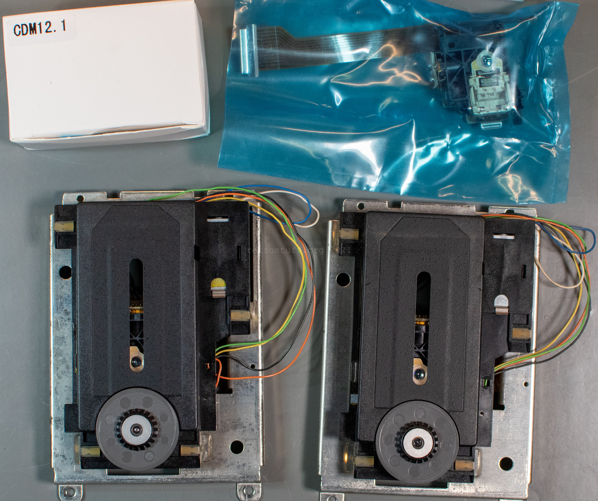
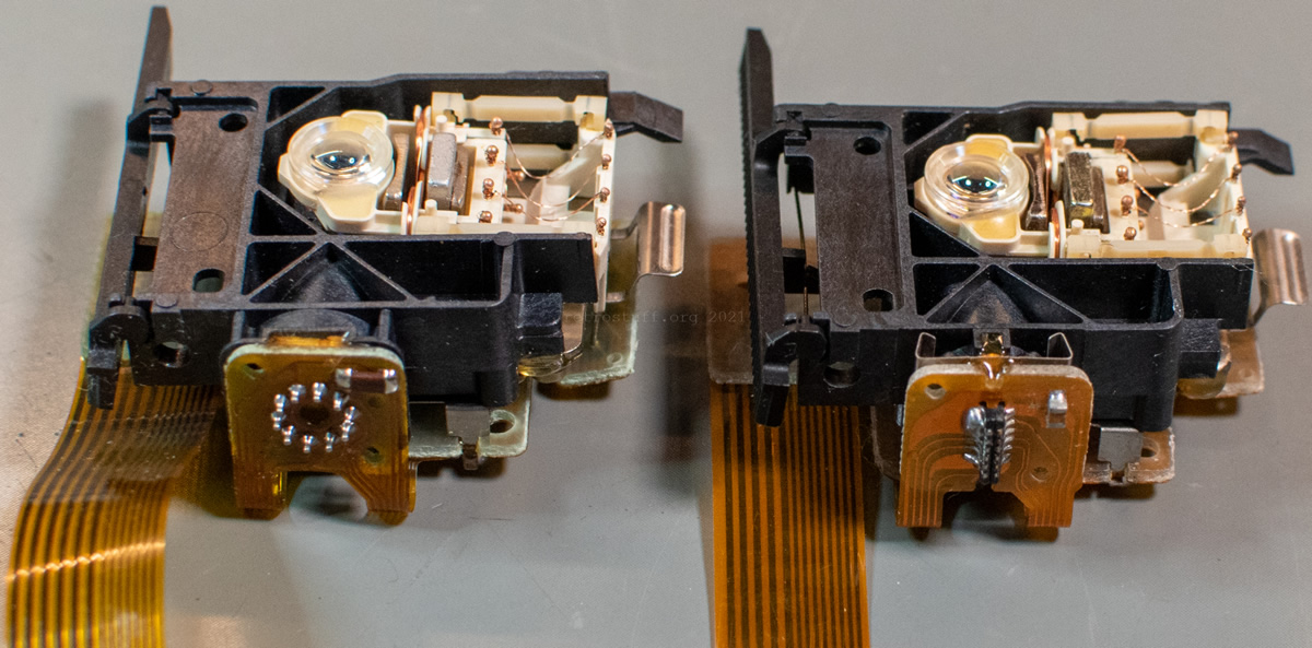
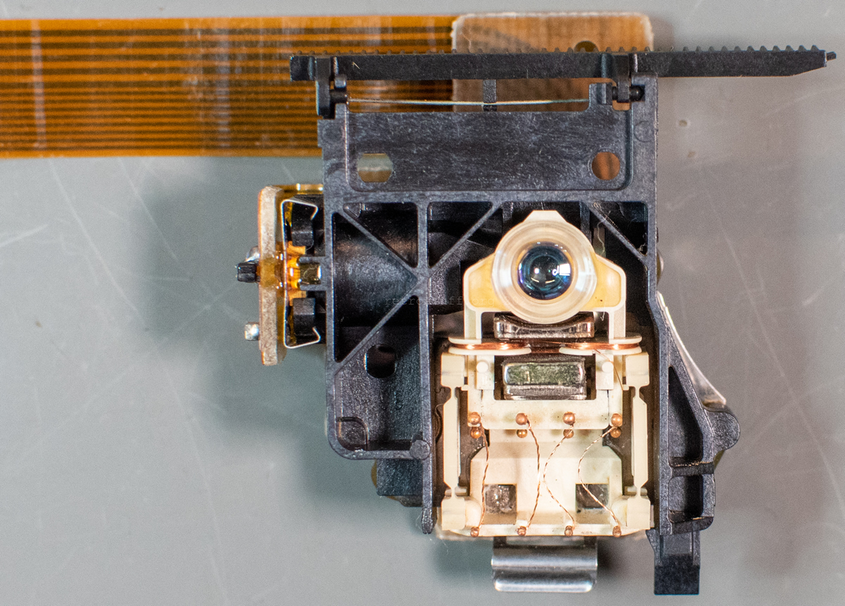
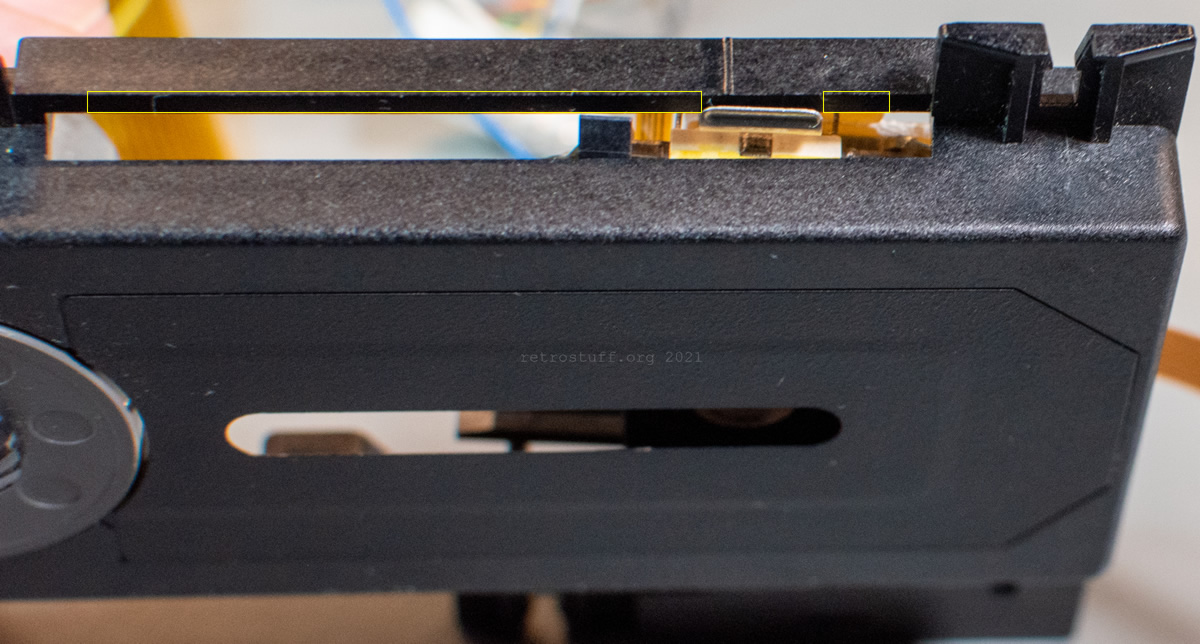
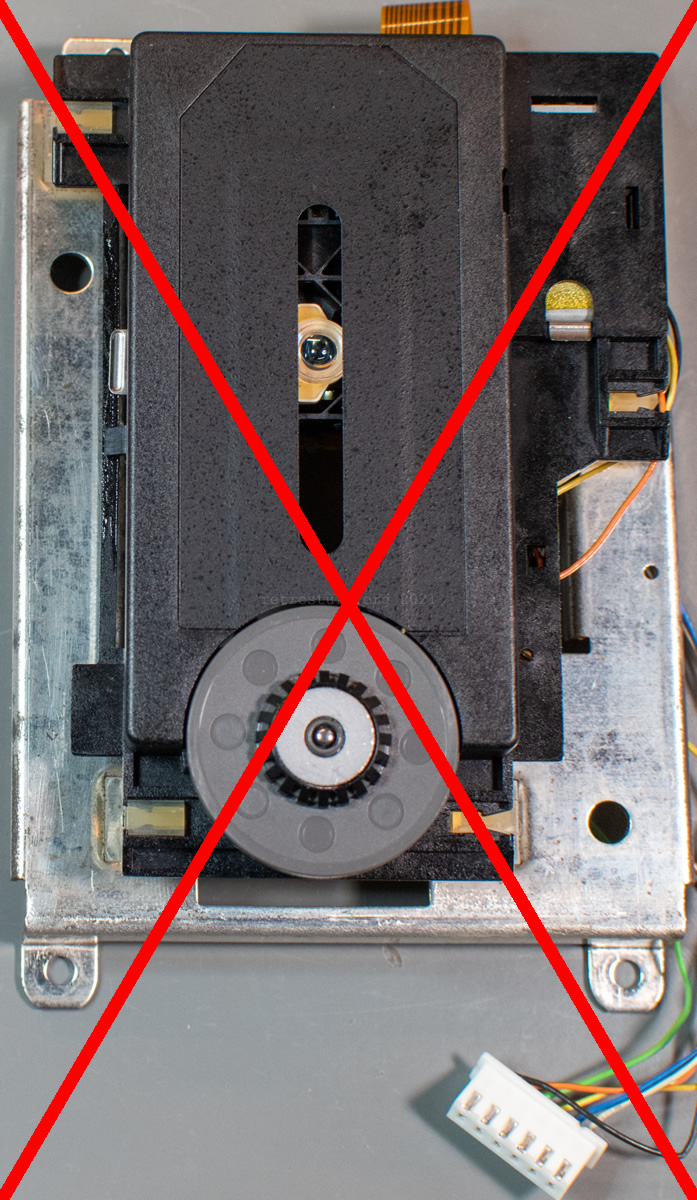
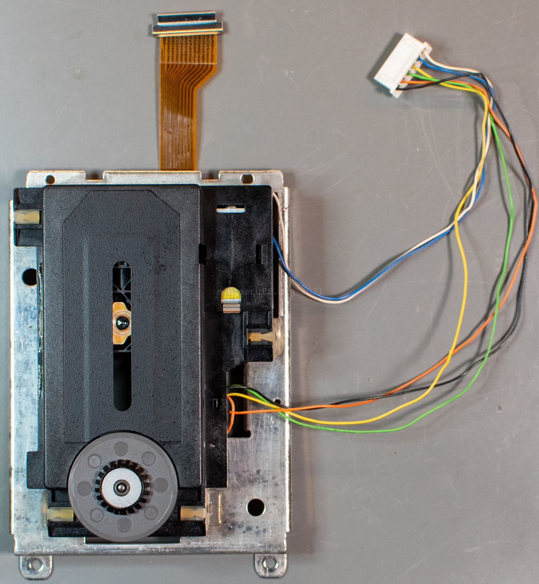
Especially when dealing with top-loading consumer CD-i players (e.g., CDI450 and 550), it is easier to replace only the laser sledge (also known as optical block or pickup). These players are using CDM 12.1T (top-loading) mechanisms with ornamental plate and shorter wires. The replacement mechanisms come without ornamental plate and either wires that are too long or no wires at all. Additional work is needed to make them suitable for use in a top-loading CD-i player.
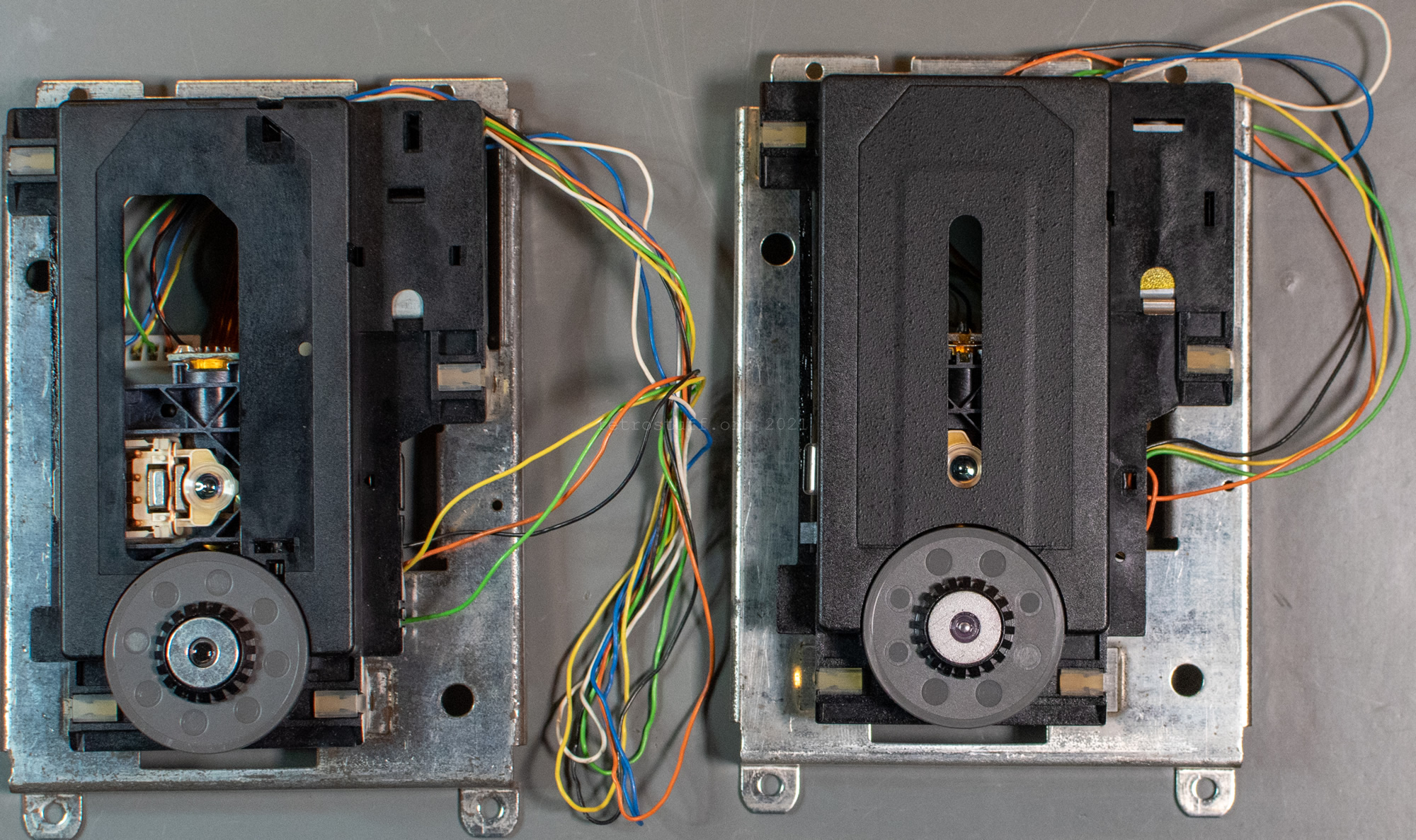
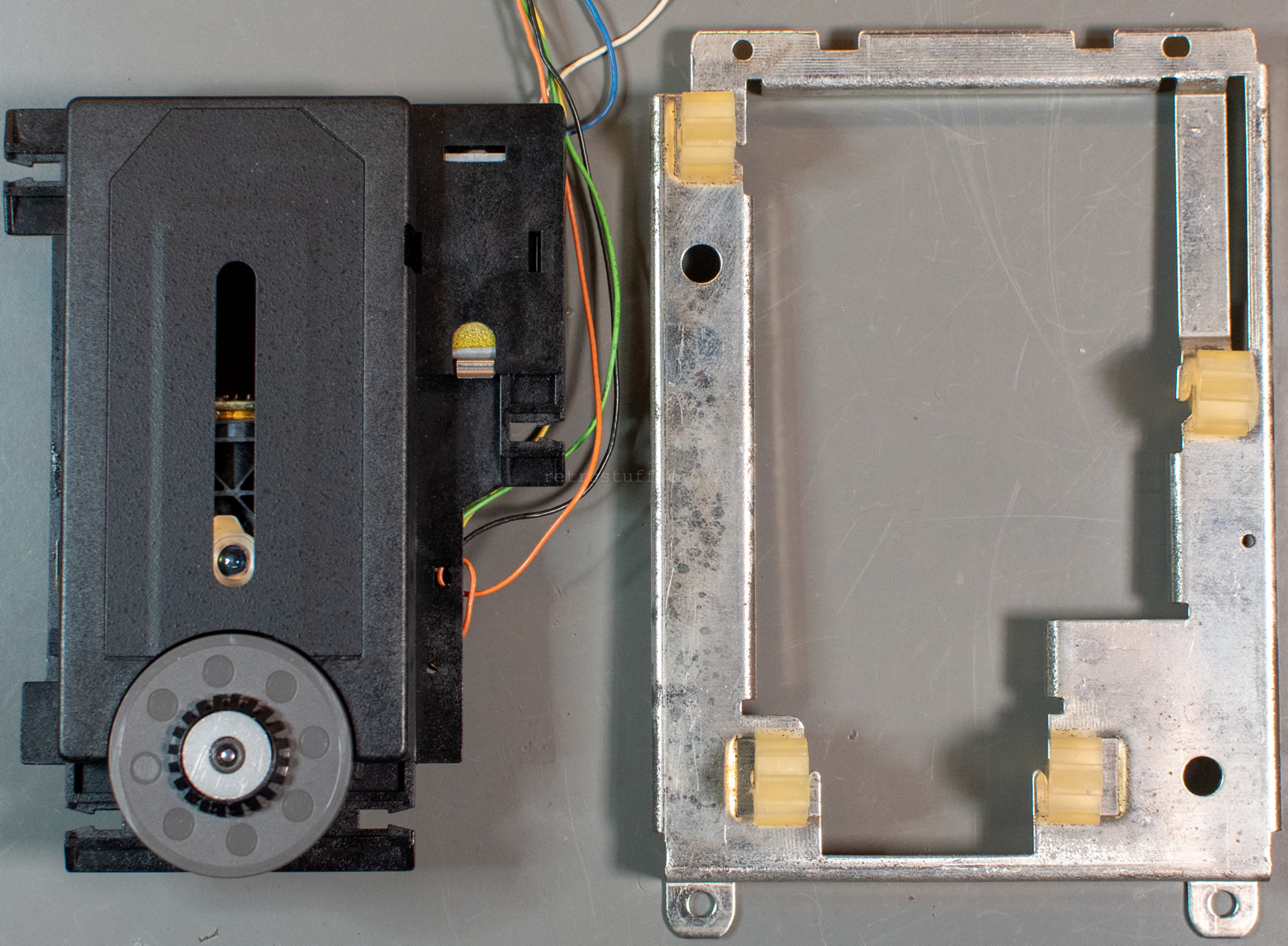
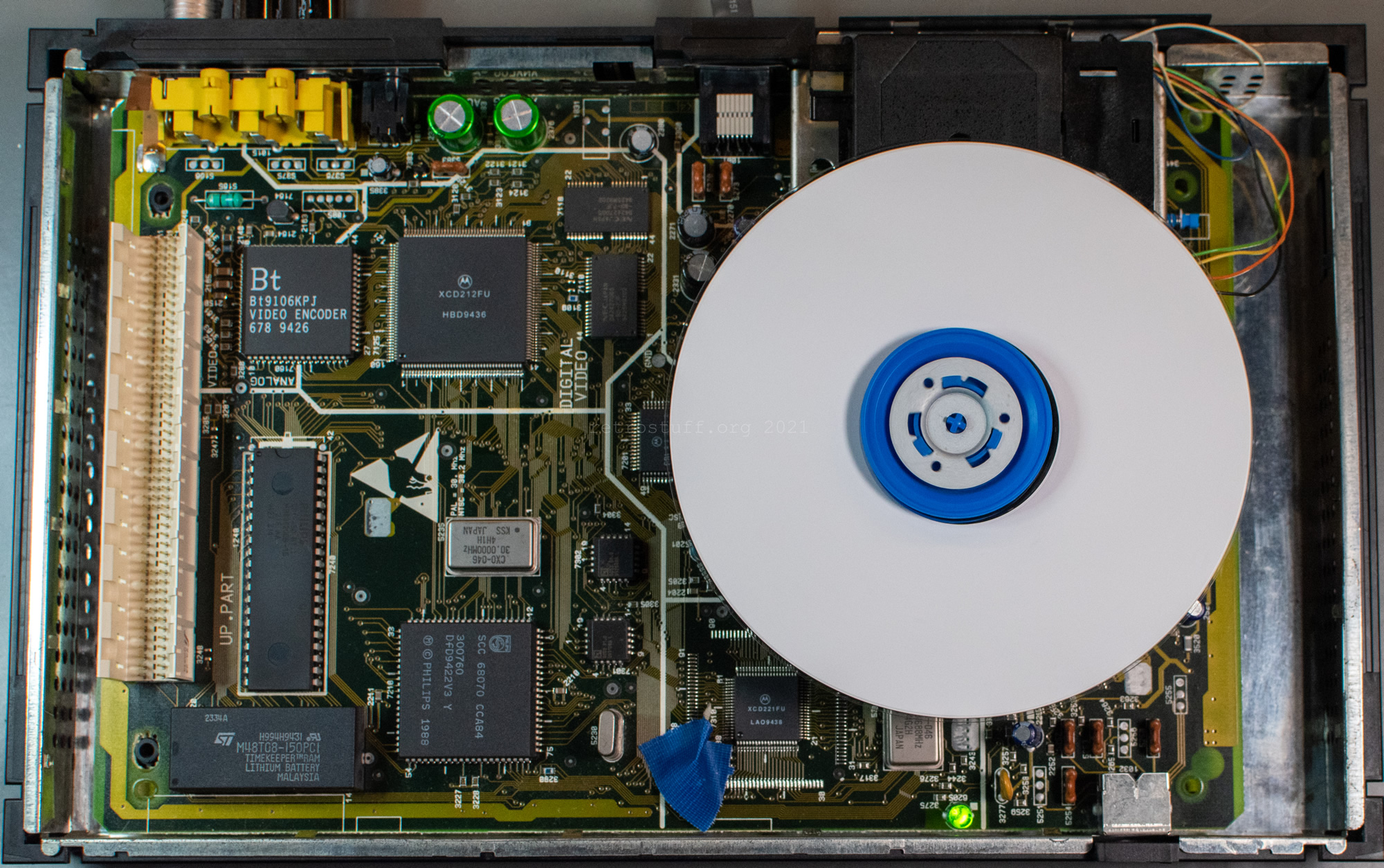
For comparison, regular on the left and top-loading on the right:
To some extent, this guide is also valid for tray-loading CD(-i) players with CDM 12.1 / VAM 1201 / VAM1202 mechanisms. Just pay attention to the different routing of the wires and the removal of the suspensions, see here.
I suggest that you read the whole guide to make yourself familiar with the procedure. Even if it sounds complicated, it is not and you’ll be able to perform it is less time than reading this guide.
Preparation
To prepare the CD mechanism that is still connected to the mainboard, we will use the Service Shell:
The operation of the Service Shell is special on top-loading CD-i players. It is mandatory that you have a pointing device of the M type: Mouse (22ER9011), Trackerball (22ER9013) or Roller Controller (22ER9012). Other controllers (e.g., gamepads) won’t work.
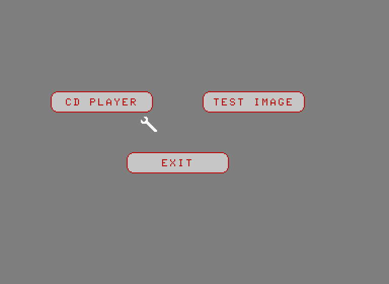
To start the Service Shell, switch the player off and insert a test/dummy plug (or short pins 2 and 3 of the controller port). Next, turn the player on and wait for the Service Shell to display. Finally, remove the plug/short and connect one of the above-mentioned pointing devices to navigate.
In this guide, we will be using the CD PLAYER menu only and especially the ARM OUT and ARM IN buttons. In some ROMs, they are called SLEDGE OUT and SLEDGE IN.
I will also mention alternate ways to move the sledge in case you don’t have access to the Service Shell.
Note: Do not look into the laser!
Enter the Service Shell, press CD PLAYER, confirm two messages and press ARM OUT once. This will move the sledge towards the end.
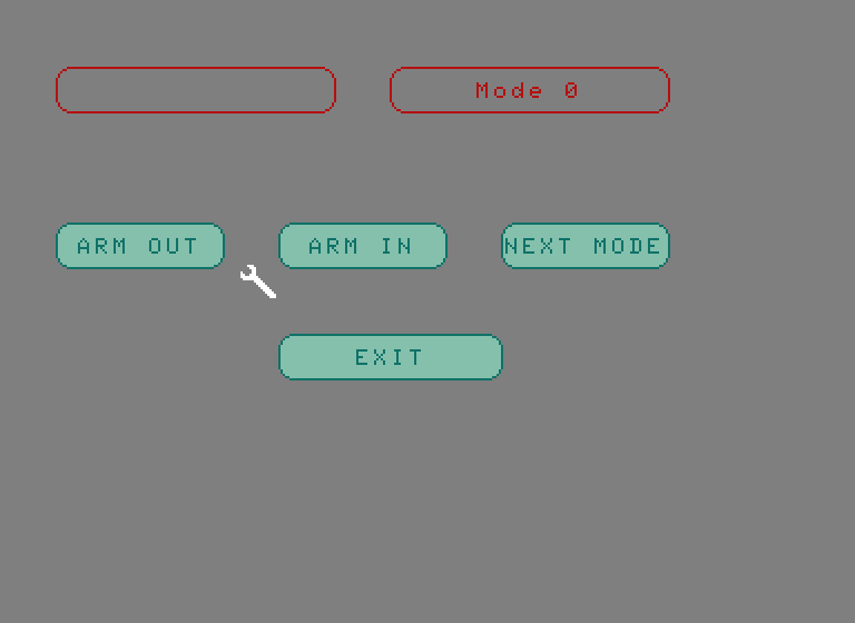
To move it all the way to the end (top), press the button again and immediately unplug the power when you hear a clicking noise. The noise is caused by the gear rack when the sledge tries to move beyond its limits. If you don’t feel safe doing that (or don’t have access to the Service Shell) then you can also move the sledge by hand, but more about that in the next section.
Dissassembly
Note: Before you start, ground yourself!
Unplug the CDM from the mainboard and place it with the support plate on a flat surface. Then, slide out the rubber suspensions one by one in the order indicated. To do so, use a blunt flat screwdriver or an opening tool to push the top of the suspensions in the direction of the arrows. At the same time, gently pull the CDM in the other direction. Be careful because the material of the suspensions is very soft and you could easily cut off parts of it.

Checking the position of the sledge
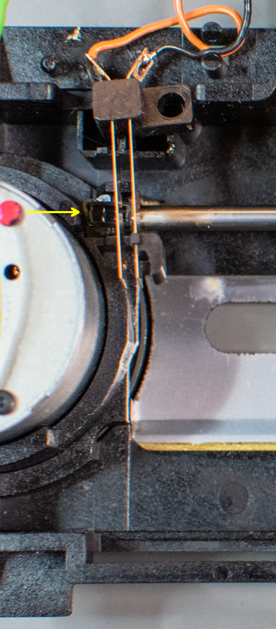
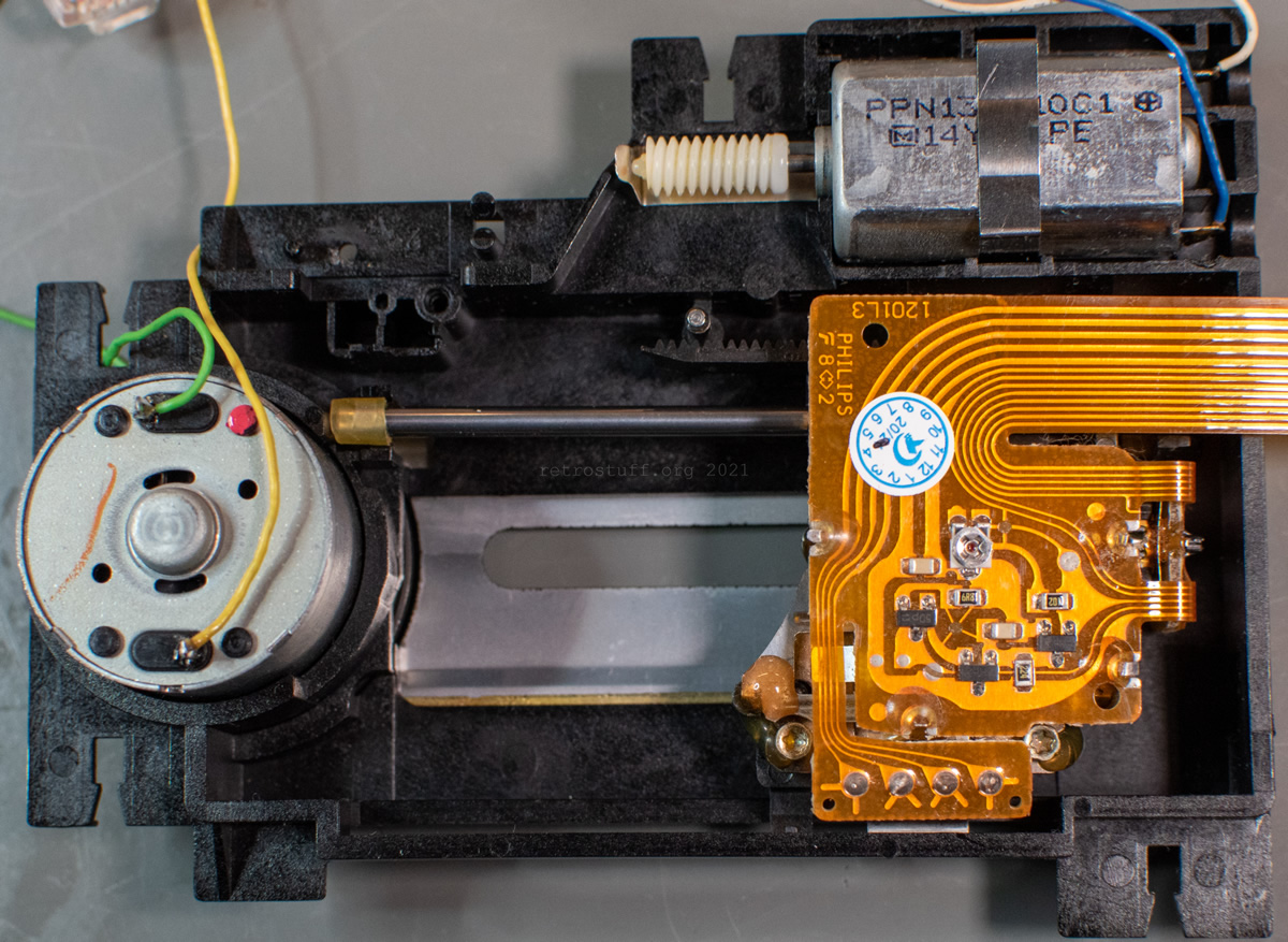
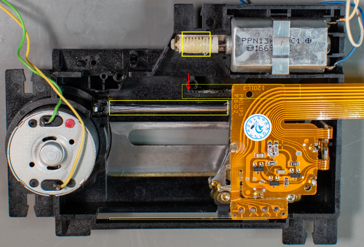
Carefully turn the mechanism around and it should ideally look like this: The laser sledge is all the way to the right and you can easily access the gearwheel. Make sure to not apply pressure onto the spindle motor on the left. Otherwise, you’ll risk to push down the turntable (more about that at the end of this guide).

If the sledge is still in the middle or on the left, you can either try it with the Service Shell, as explained above, or move it manually. To do so, rotate the worm gear on the sledge motor up with your finger. The sledge will move only very slowly and it will take many rotations until it is finally on the right. Note: Protect your finger if you don’t want to touch the old grease.

Disassembly (continued)
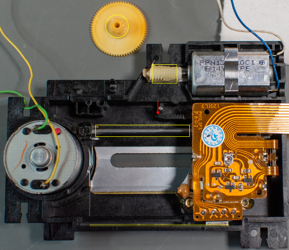
When the sledge is all the way to the right, lift the gearwheel up. Sometimes, it comes out on its own and sometimes, the spindle is still attached to it. Either way, it should happen without force.
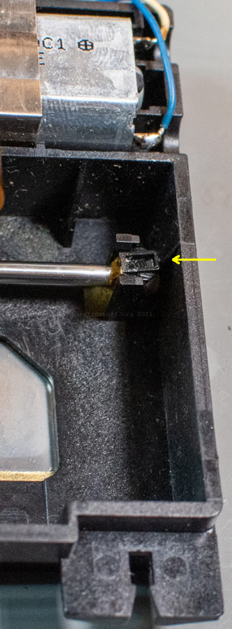
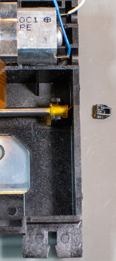
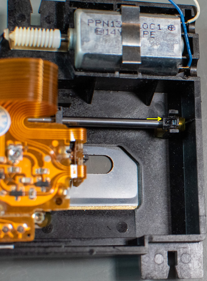
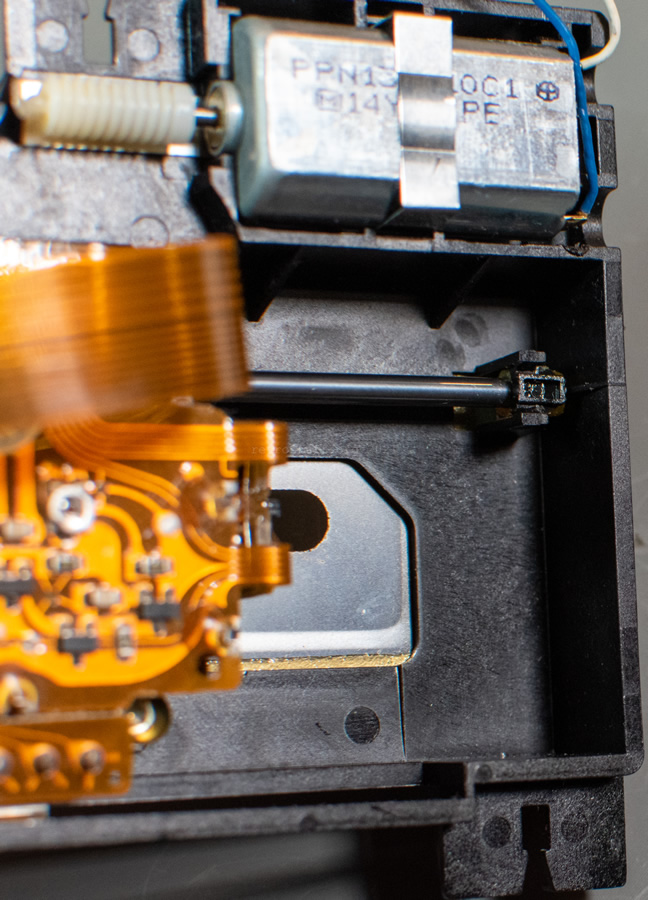
When this is done, the sledge is no longer locked and you can move it freely. Next, we want to remove the steel rod that is held by two tiny plastic wedges left and right. The left end is covered by a switch. Take notes (or photos) of the wire routing and then unscrew it with a Torx T6 screwdriver.
Push the wedges with a flat screwdriver into the direction of the arrows to take them out:
Now that the rod is free, you can pull it out together with the laser sledge.
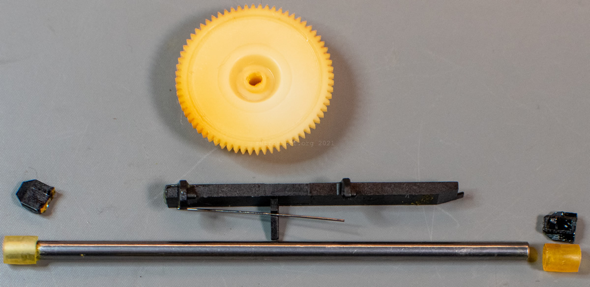
These are the small parts that we have taken out so far. Also seen in the centre: The gear rack and the spring wire that were accidentally unclipped from the sledge. Don’t worry if this also happened to you because you won’t need these two parts anymore.
Cleaning
First, let the gearwheel, the metal rod and the two wedges soak in isopropyl alcohol (IPA). Also, clean the two pieces of silicone/rubber tube, but don’t let them soak.
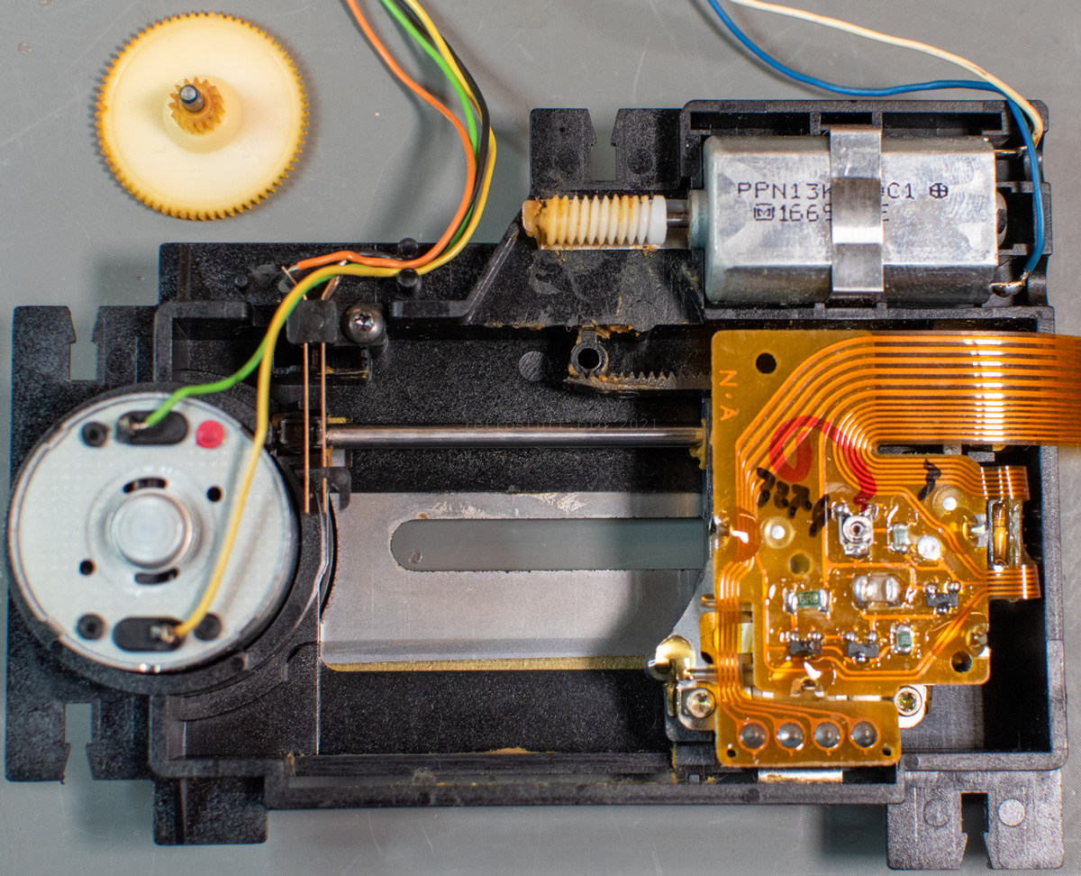
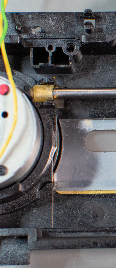
Then, clean the marked areas (and wherever else dried grease ended up). Take your time and thoroughly remove every bit with tweezers and Q-tips soaked in IPA. For the worm gear, take a piece of kitchen towel, slide it underneath it and soak it with IPA. You can easily clean it now by turning the worm gear up and down with your fingers. Replace the piece of kitchen towel and repeat until the gear is clean. I don’t recommend removing the sledge motor because the bottom is glued to the case.
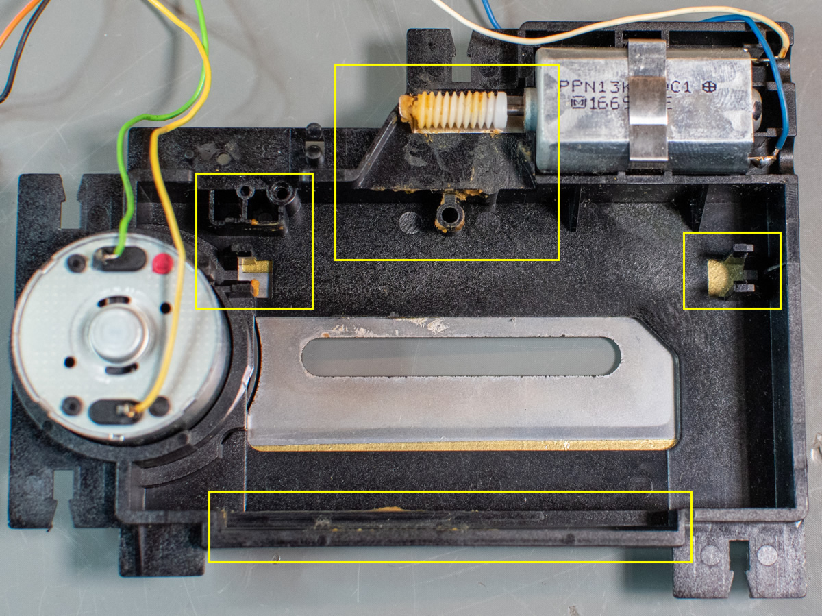
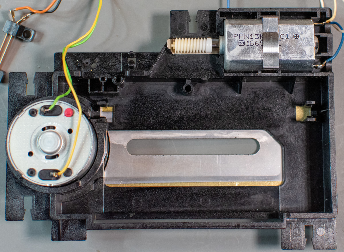
This looks much better:
Finally, clean and dry the pieces that were soaking in IPA.
Assembly and greasing
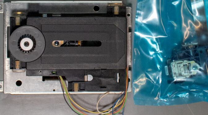
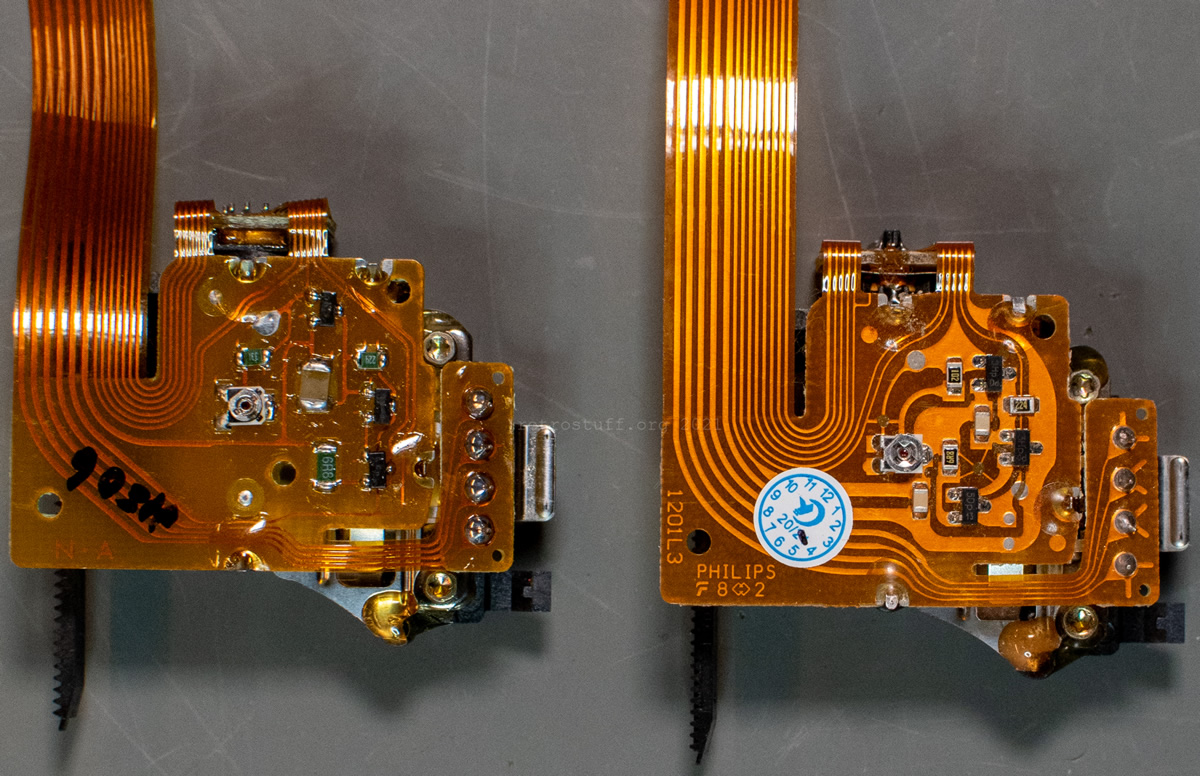
First, make yourself familiar with the new laser sledge, especially how the gear rack is attached to it. You will have to push this rack towards the sledge later without accidentally unclipping it. For comparison, old and new laser sledge side by side and a close-up of the new sledge.

Assembly: Laser sledge
Begin with the metal rod: Slide it into the laser sledge and secure the ends with the two pieces of rubber tube.
Then, place the sledge into the case as shown below with the curved metal piece first. Also, take note of marked area: This is where you’ll have to apply a thin layer of grease in the next section.
Place the steel rod with its ends onto the plastic hooks and push it down gently.
Place the right wedge with its arrow-shaped end between the two hooks and push it with a flat screwdriver until it snaps in place.
Attach the left wedge as well and the steel rod is locked in place.
Applying the grease
I used a Teflon/PTFE-based grease for model-making and applied it with a small wooden spatula.
There are four areas that need to be greased: The steel rod, the marked area on the opposite end (see last section), the worm gear and either the gear rack or the smaller gearwheel – whatever is easier for you. Both options are shown here:
If you don’t have access to the Service Shell, now is a good time to move the sledge back and forth to evenly apply the grease. For the worm gear, gear rack and gearwheel, play an audio CD when testing (see last section).
When you’re done, push the gear rack (red arrow) towards the sledge and attach the gearwheel. This will lock the sledge in its current position. Make sure to attach the switch again and route the wires according to the notes/photos that you took before.
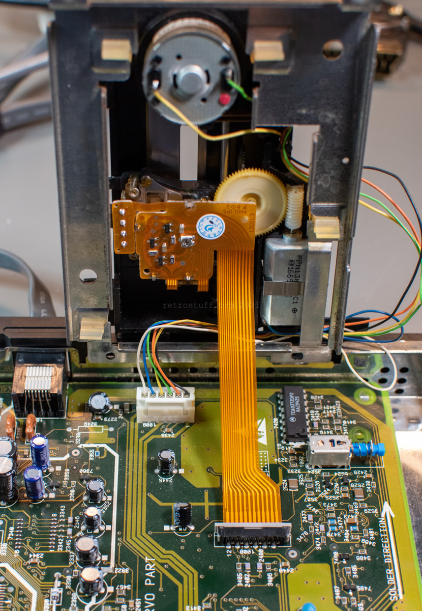
Next, we will use the Service Shell to apply the grease evenly. Place the CD mechanism as pictured and plug the motor/switch connector into the mainboard. Then, boot into the Service Shell, go to CD PLAYER and press ARM IN twice. This will move the sledge all the way towards the spindle motor. It will automatically stop when it hits the switch.
To spread the grease, press ARM OUT and ARM IN once alternatingly for a couple of times.

Unplug the CD-i player and the CD assembly and do a last visual inspection.
Assembly (continued)
Before attaching the CD mechanism to the rubber suspensions of the support plate again, pay attention to the routing of the wires. Route/align them as seen on the right picture:
Next, just slide the suspensions back in one by one. You won’t need a lot of force or a tool this time. Start in the upper left corner and then continue counter-clockwise.
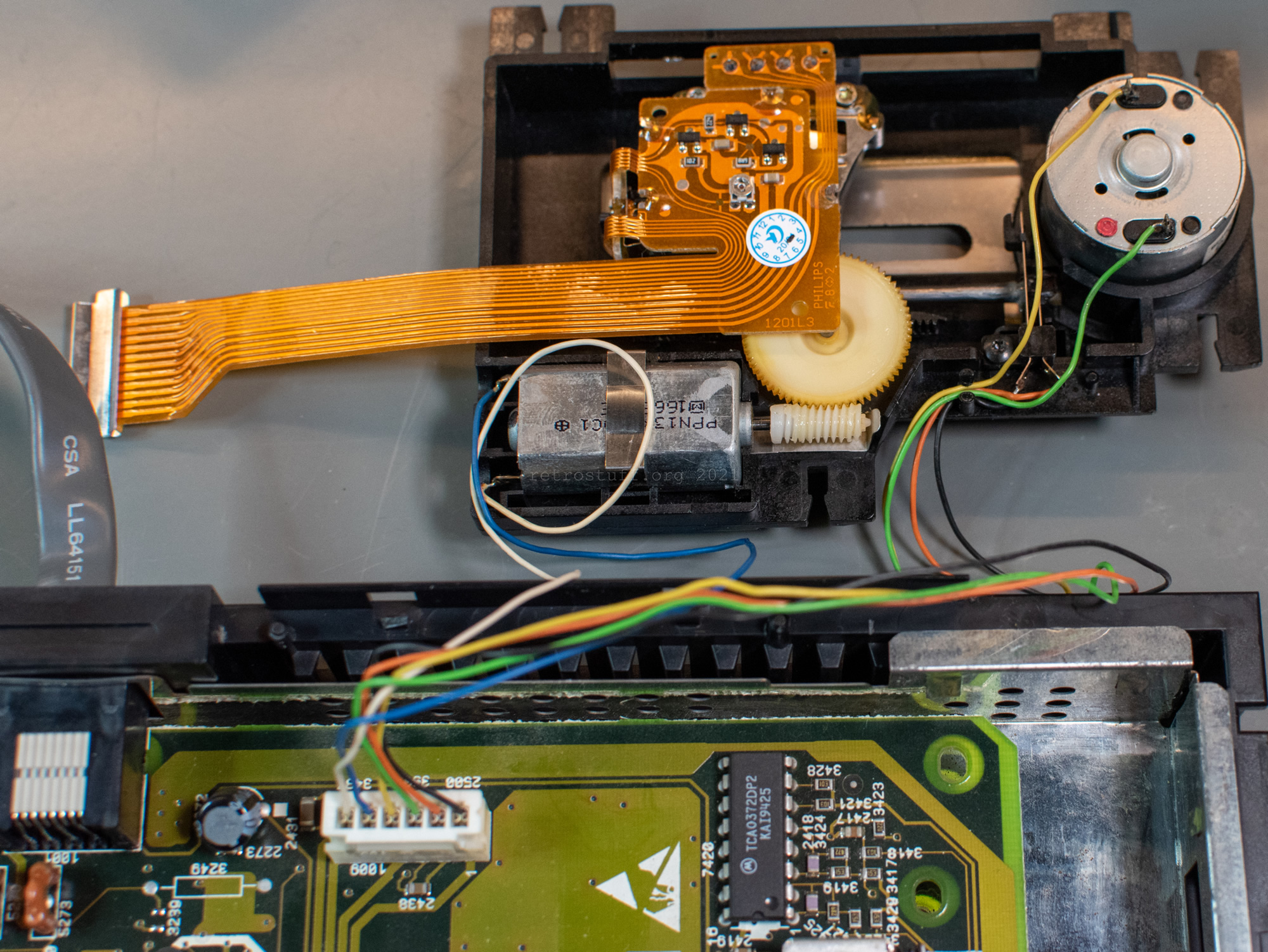
Then, thread the motor/switch connector through the back, remove the protector of the laser FFC and connect everything to the mainboard.
Testing and finishing touches
Finally, it’s time for some testing. I’ve placed a fitting clamper from an old PC CD-ROM drive onto the disc and some tape on the lid switch to make play without the top cover of the CD-i player. I used a burned CD+G disc that some of my players have trouble with and tried to go through all tests of the Service Shell, as explained here.
If you don’t have access to the Service Shell, simply play an audio CD. Either from start to end (if you have the time) or by randomly skipping through the tracks to make sure that the laser sledge reaches every position. This will also help to spread the grease.
Pretty soon, I noticed that something was wrong. The spindle motor had trouble running at full speed. It turned out that I had accidentally pushed down the turntable while working on the laser sledge.
If this happened to your CD mechanism, push the turntable upwards evenly with a flat tool, as explained here or in The World of CD-i tutorials. When it is back at the correct height, run the CD tests of the Service Shell (and/or play an audio CD) again. It’s a good idea to run the test with the top cover in place. Open the lid and push the lid switch down with screwdriver (don’t look into the laser!). You’ll see it right away if the disc wobbles/touches the case. Adjust the height again until it runs smoothly. Don’t forget to remove the clamper before closing the lid!
After I had adjusted the height of the turntable, I added a blob of threadlocker (Loctite) on top of the spindle and let it cure for 24 hours.

That’s all! The replacement of the Philips CDM 12.1T laser sledge was successful and you won’t have any more problems playing discs in your CD-i player.
I have a CDI 550 with issues, games freeze after playing them for a few minutes. I ordered a new laser. The old assembly has a label of 12.1T and the new one has VAM1202. Are these compatible to swap?
Just to add some additional things. When I swapped them out the VAM1202 didn’t read discs. I tried adjusting the potentiometer but still nothing.
Before you replace or adjust anything, I would suggest that you look at the entire article and start from scratch. If cleaning and greasing do not change the behaviour [of the CDM 12.1T], then simply replace the laser sledge and not the complete CDM/VAM. The potentiometer does not need to be adjusted if the spare part is really brand new.
hi guys…for a few days my cdi 550 has been acting up…when I connect the charger and turn on the console the cd rom motor starts to spin quickly….when I press the door switch it stops… I insert the disc…the laser turns on but the motor moves slightly and then stops…the green light is intermittent…can you help me? thanks
Check the CD mechanism with the Service Shell as described in this and the 470 repair article.
You may also want to check the voltages coming from the power supply (the player must be switched on).
hi…thanks for you answer…the correct voltage arrives…+5v and -5v are present on the motherboard…can I attach a video? it’s possible?
That’s good. Next, use the Service Shell.
You can’t upload a video here. It’s probably easier to continue this on the CD-i Discord server (https://discord.gg/TKPejTfw6D) or in one of the CD-i Facebook groups.
ok…guys….I used a tester…I noticed that there are some capacitors that have their pins in contact….they have continuity….I think there is a problem….
hi everyone…when I turn on the console the CD rom motor starts to turn…only by pressing the door switch does it stop…I found a three-sided piece of copper…one side with a slot. ..another one with a tab…appears to be a ground…do you know where it should be installed?
The piece of metal that you describe probably belongs under the mainboard/power socket.
It is completely normal for the motor to turn when a disc has been inserted and detected. If it just spins without a disc then it could be anything, e.g. short circuit, pinched cable, defective Timekeeper. But as mentioned before, please use Service Shell and if you get stuck, Discord or a CD-i Facebook group are better suited for diagnosis.
thank you for you answer….I changed timekeeper…it works perfectly…I noticed that cdi ricognize cd rom…but motor spindle spins little degrees and than stops
Ok, let’s continue with the troubleshooting on Facebook
ok…thank you…can you explain me how tk make a “special tool” to use to see the service shell? I dont undestand
Hi,
Thanks for sharing. Where did you buy that blue CD clamp in image CDM121_32.jpg? Thanks in advance.
I found it in a box with parts from broken PC CD- and DVD-ROM drives that I had disassembled years ago.