
50/60 Hz modifications are quite simple hacks that have been figured out for almost all Philips CD-i player types with SCART connector. But what about all the CD-i players that do not have an RGB output, either because of reduced cost or because they have been sold outside of Europe? Technically, they can still be modified, but the foreign mode is pretty useless and results in a black and white picture or no picture at all.
The reason is easily explained: All Philips CD-i players have a main system clock at either 30,0000 MHz (PAL) or 30,2098 MHz (NTSC) and additional clock generators for some components. All newer players (Mono III and up) have a Brooktree video encoder and generate the colour subcarrier frequencies (PAL 4,4336 MHz and NTSC 3,5795 MHz) from the system clock. The older players with a Sony video encoder use one or two additional crystals and some more components for this task.
When we modify/switch a PAL CD-i player to 60 Hz without changing these crystals/oscillators as well, then we not only lose the colour, we also never reach 60 Hz (NTSC is actually 59,94 Hz, but we will round it up). It is always slightly below (e.g. 59,5 Hz on my CDI470). This affects other game consoles as well, by the way, and can be troublesome for some modern TVs and video processors.
Dual frequency oscillator
I’ve been thinking about a dual crystal solution for quite a while now, but never got any further than not finding a 30,2098 MHz crystal oscillator anywhere. Then the DFO (dual frequency oscillator) project (German / English) caught my attention. It uses a TI CDCE913 programmable clock synthesizer to generate two frequencies. There is also another project, MFO (multiple frequency oscillator), that generates even four frequencies.
Unfortunately, you cannot buy these. VideoGamePerfection and Otaku’s Store had the DFO for a while, but not anymore. And even then, the boards came pre-programmed for either Sega Mega Drive or Sony PlayStation. Custom frequencies for the Philips CD-i, require a programmer, and these are also not sold anywhere. There is an alternative though, cdceprog for the Raspberry Pi.
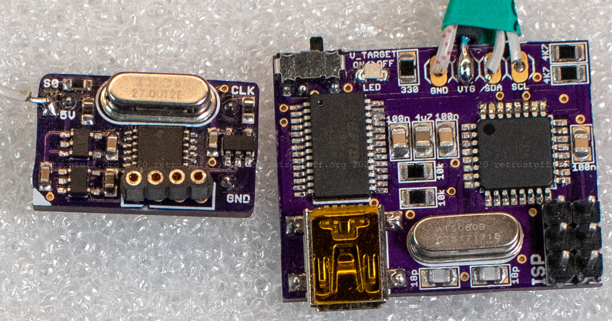
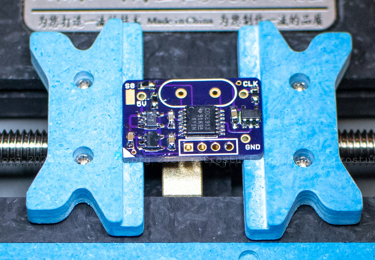
When tired of waiting, I finally ordered the PCBs for DFO and programmer from OSH Park and the components from Mouser last year. Only the 1 µF SMD capacitors weren’t available there, so I had to buy them from a Chinese seller on eBay. Then, I baked one of each board in a reflow oven. This is how they look at the moment, with additional connectors for programming:
Preparation
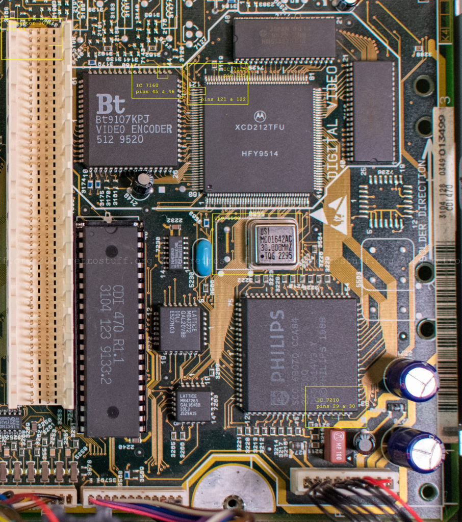
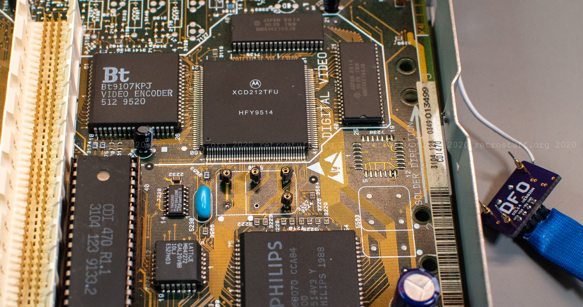
Before adding the switch and DFO to my CDI470/20, I reset it to the initial configuration (ROM and NVRAM). Then I measured system clock frequencies (PAL) on the points indicated in the service manual.
- System clock (PAL): 30,0000 MHz (± 50 ppm / 1500 Hz) on IC 7210 pin 30 (CPU SCC 68070) and IC 7125 pin 115 (VDSC XCD212TFU)
- System clock (NTSC): 30,2098 MHz (± 20 ppm / 604 Hz) on IC 7210 pin 30 and IC 7125 pin 115
- Clock / 2 (PAL): 15,0000 MHz (± 50 ppm / 750 Hz) on IC 7210 pin 29
- Clock / 2 (NTSC): 15,1049 MHz (± 20 ppm / 302 Hz) on IC 7210 pin 29
- XT2N clock (PAL): 15,0000 MHz (± 50 ppm / 750 Hz) on connector 1096 pin C3
- XT2N clock (NTSC): 15,1049 MHz (± 20 ppm / 302 Hz) on connector 1096 pin C3
There are some more interesting points to check the video output frequencies:
- NVSYN!: ~50 Hz on IC 7125 pin 121 and IC 7160 pin 46 (Hobbes BT9107KPJ)
- NHSYN!: ~15 kHz on IC 7125 pin 122 and IC 7160 pin 45
After I had verified that everything is within range, I began with the modification.
Installing the PAL/NTSC switch
This is basically the same procedure as for the CDI660 since both CD-i players have a Mono IV mainboard.
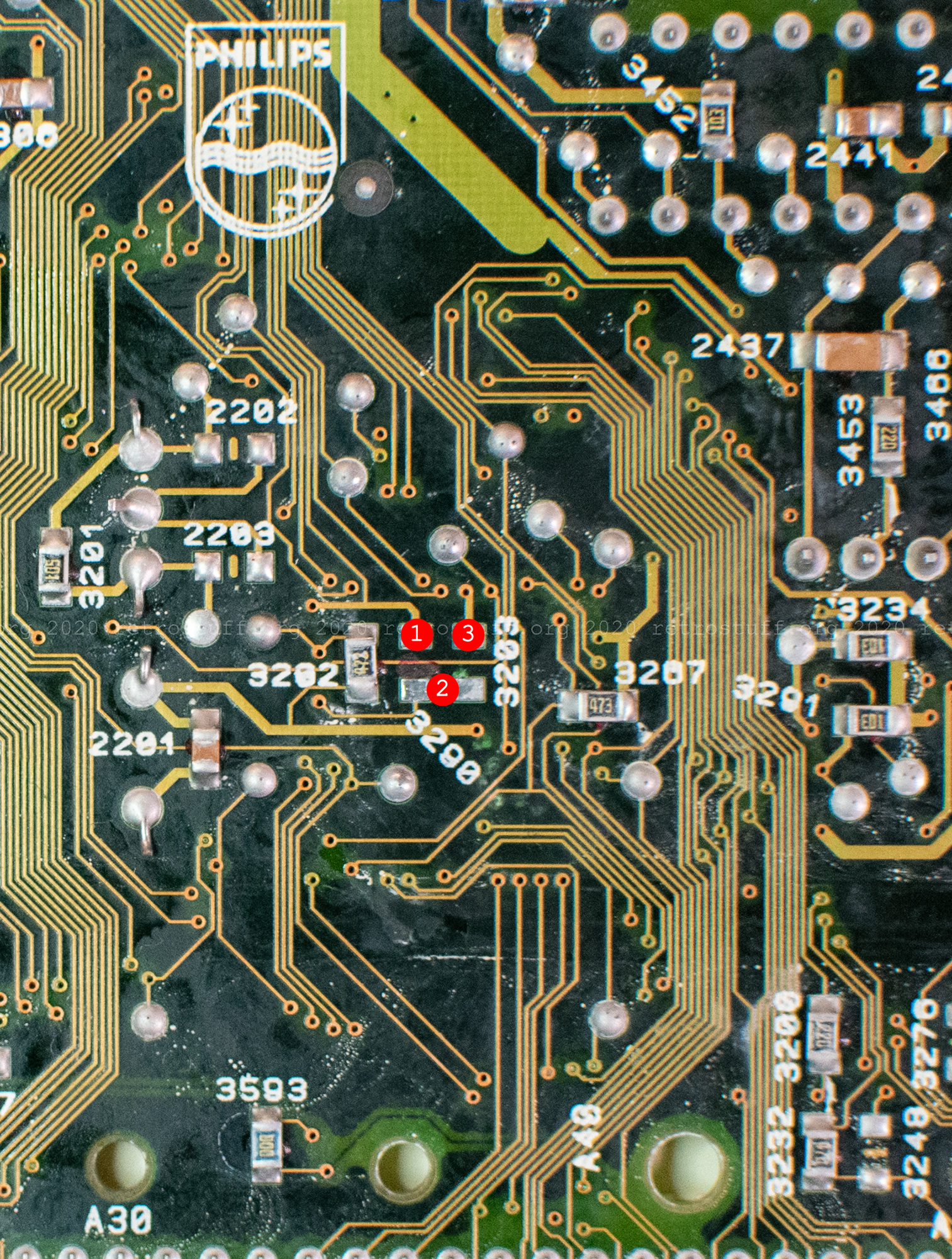
The STANDIN! signal on pin 58 tells the CPU if the CD-i player is from the PAL or NTSC region and changes the frequency of the video output to either 50 or 60 Hz. Two jumpers (10 kΩ resistors) 3203 and 3290 set the signal.
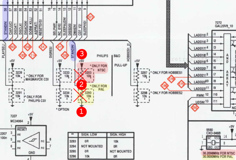
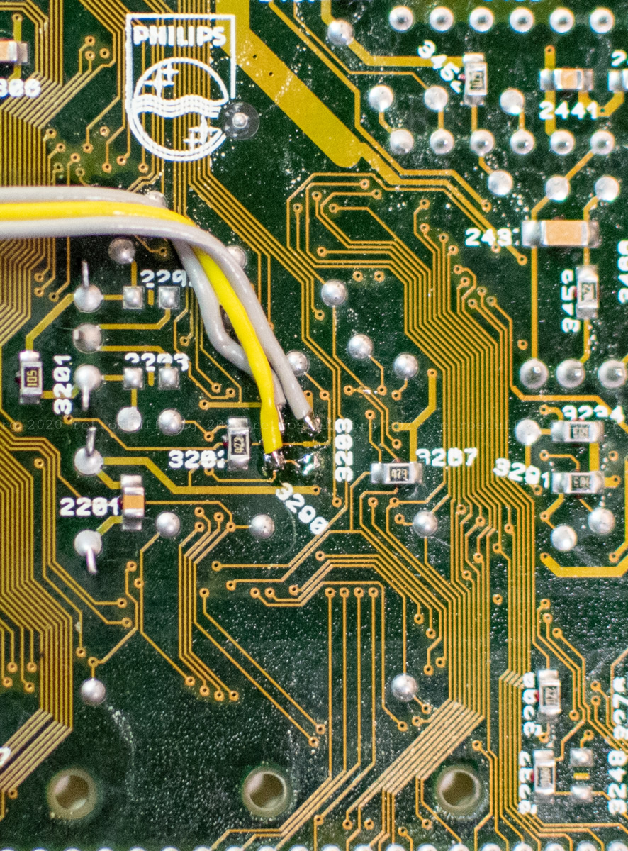
First, I removed the resistor 3290 and cleaned the pads. Then I added three wires to the points (1) = GND, (2) = STANDIN! and (3) = +5V and secured them with tape.
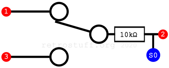
Next, I soldered a 10 kΩ resistor to the centre pin of an SPDT (single pole, double throw) switch. Then, I soldered the wire from (2) and a second wire (S0 / DFO) to the other end of the resistor. Finally, I soldered the two wires from (1) and (3) to the outer pins of the switch and secured everything with heat shrink tube.
Installing the DFO
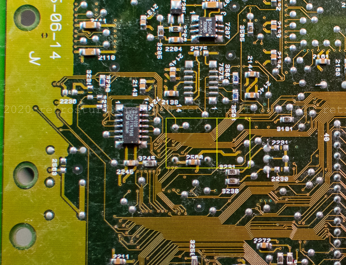
The DFO comes in the size of a DIL-14 package, while the original crystal oscillator 5560 (CXO) is a DIL-8 package.

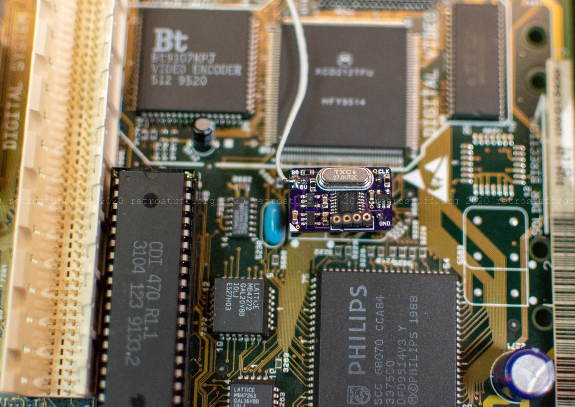
The Mono IV mainboard has enough a space for both package types. Carefully, I desoldered the CXO 5560 from the back. As usual, at least one of the pins was soldered from both sides. This required a powerful desoldering gun and a lot of patience.
Next, I fitted four pieces of a precision socket. With this socket, I was able to use oscillators of both package types and swap them for further tests. The two pins on the lower left can be omitted.
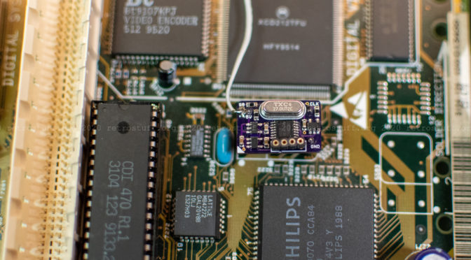
Finally, I fitted the DFO and attached the additional center wire from the 50/60 Hz switch to S0. This will switch between the two system clock frequencies. For NTSC S0=1 (high) and for PAL S0=0 (low).
Programming frequencies
To calculate and program the desired frequencies 30,0000 MHz (PAL) and 30,2098 MHz (NTSC) to the DFO, two programs and the programmer hardware are needed:
With TI ClockPro and the tutorial from the project page, I calculated my first pair of frequencies and saved the result as Intel .hex file.
With the CDCE9XX Programmer hardware and software (the current version is 1.1), I programmed the .hex file to the DFO.
The results were somewhat unexpected: In NTSC mode, I finally saw a nice, colourful image. The PAL mode, however, was now flickering and with wrong colours. I checked the frequencies thoroughly with my frequency counter and oscilloscope, and it turned out that they were about 1 kHz lower than expected (and programmed).
I removed the DFO again and put the original crystal oscillator back into the socket. After thorough tests of both oscillators in the CD-i player and in a testing board, I came to the conclusion that the CD-i player runs fine and that my DFO must be faulty.
Further tests and calculations
I assembled another DFO and soldered every component by hand.
This time, the frequencies were about 1,1 kHz lower than programmed. I can only assume that this is caused by the cheap 1 µF capacitors; each DFO uses three of them. A quick check of the remaining capacitors showed that not a single one was within the specifications. It will take a while until I’ll order the next batch of components, so the faulty boards will have to do the trick for now. They are still useful for this experiment, as they output the (too low) frequencies steadily and reliable.
A big advantage of the DFO is that you can program it on the fly, while the CD-i player is switched on. Important: V_Target of the programmer needs to be switched off.

That way, I was able to raise the frequencies little by little until both targets were met. The video output became colourful in both PAL and NTSC mode.
This archive contains two .hex files:
- CD-i_test.HEX with 30,0000 and 30,2098 MHz, this is my initial calculation.
- CD-i_test1.HEX with adjusted frequencies to compensate for my quirky DFOs.
Please try them out and let me know of your results. Until then, I’ll need to make some time to assemble more DFOs that hopefully work more accurately.
PAL/NTSC sample pictures
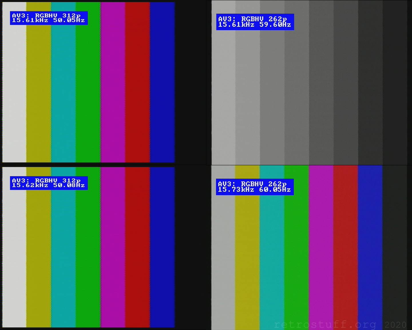
I recorderd these samples with an Avermedia Game Capture HD II, while doing tests with various video processors (RetroTINK2X + OSSC, Framemeister and DVDO iScan VP50 Pro). Unfortunately, the capture device refused to display/record anything from the device with the best looking output (iScan VP50 Pro).
I’ve adjusted the aspect ratios manually to somehow mimic how it looks on my TV. This adjustment is not accurate at all and only loosely based on the pixel aspect ratio.
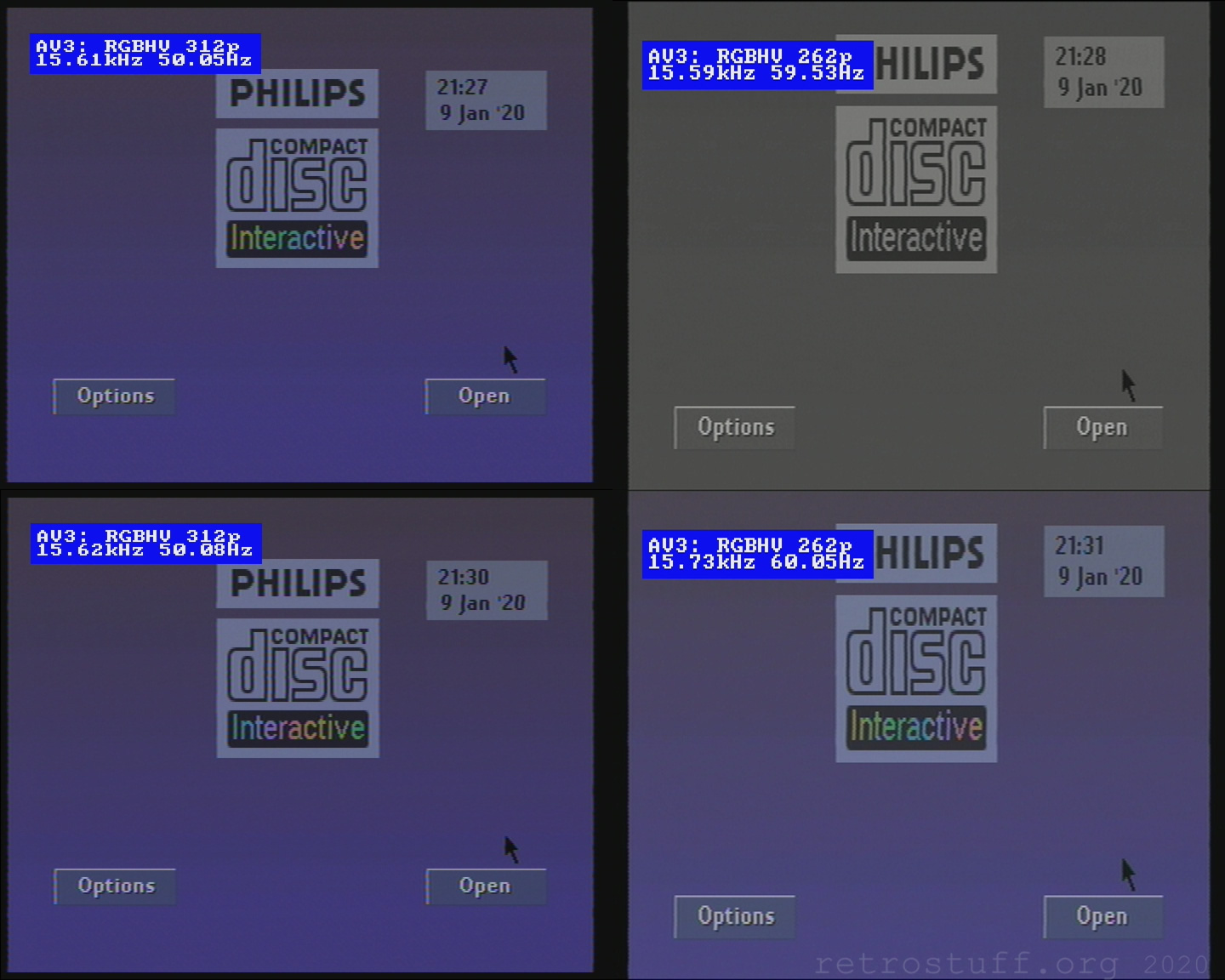
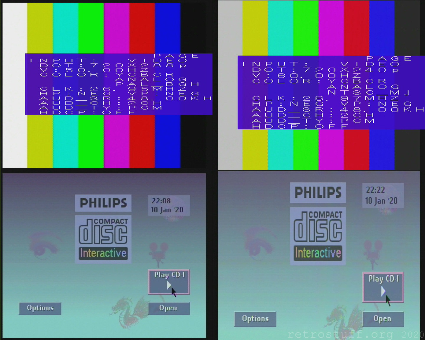
RetroTINK2X + OSSC
Upper left: PAL 50 Hz mode (CXO 30,0000 MHz)
Upper right: PAL 60 Hz mode (CXO 30,0000 MHz)
Lower left: PAL 50 Hz mode (DFO 30,0000 MHz)
Lower right: NTSC 60 Hz mode (DFO 30,2098 MHz)
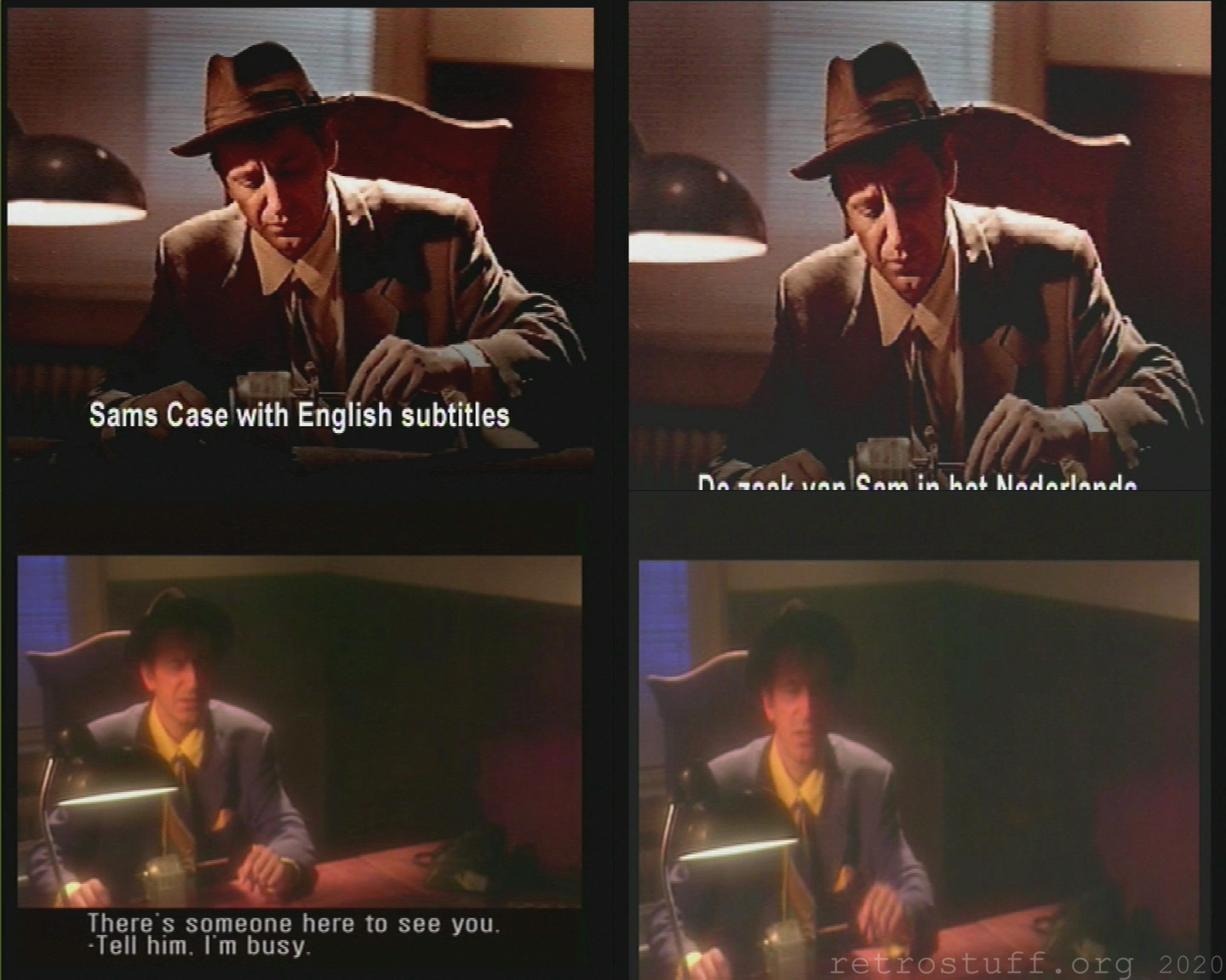
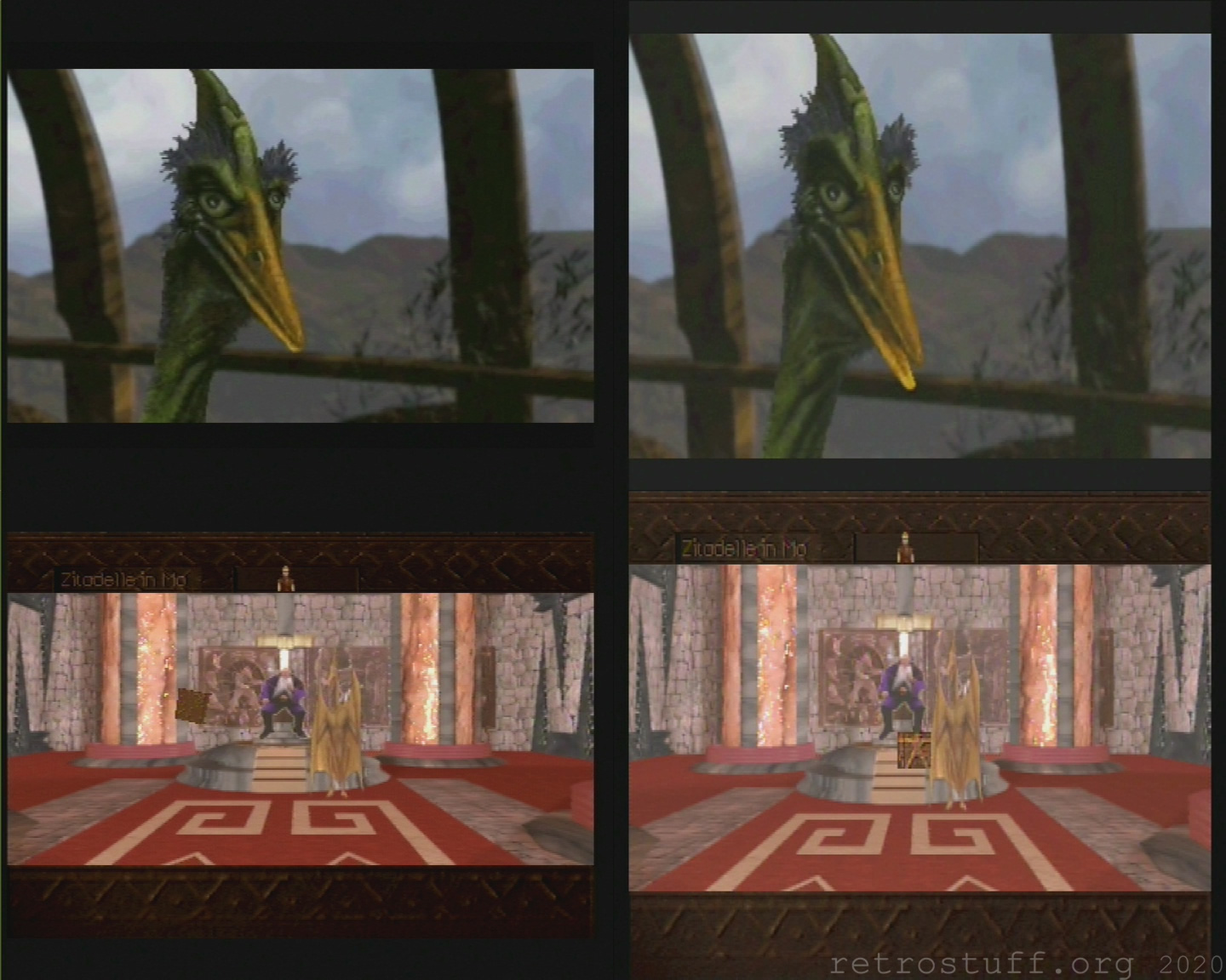
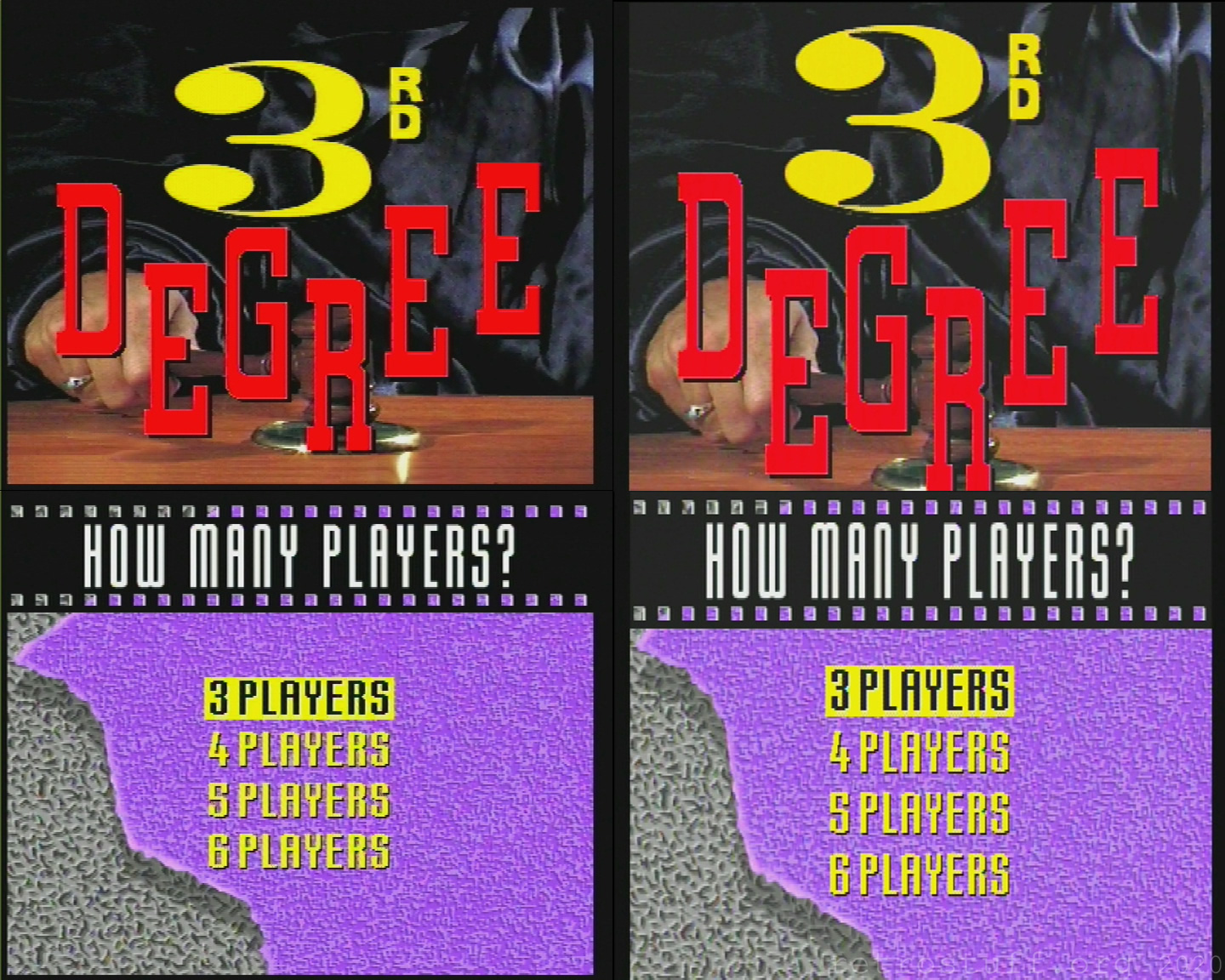
Framemeister
The Framemeister doesn’t like 60 Hz with the original crystal oscillator and doesn’t display a picture at all. It also displays an annoying bright stripe on the left of all PAL images. But I took a lot of pictures with it, so here they are:
Left: PAL 50 Hz mode (CXO or DFO 30,0000 MHz)
Right: NTSC 60 Hz mode (DFO 30,2098 MHz)

Could you link to a list of components for the DFO and programmer please?
DFO is not my project. But you will find everything you need if you follow the links in the article.
Thanks. I found the link near the top. I don’t know how I missed that.