
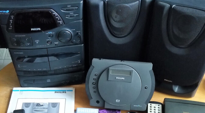
The Philips FW380i Mini System landed unexpectedly on my repair table last August. I never intended to get one of these models because the CD-i part is at the lowest end of CD-i hardware (very similar to the Roboco mainboard of CDI450 etc.) and also the build quality of FW mini system is not something I would have bought or used in the 90s. However, this particular CD-i mainboard was only used for this model and has some very unique features such as a separated servo board, a connector for communication with the FW part and even some unused connectors for a disc changer – which unfortunately never saw the light of day. Long story short: this model was never properly analysed, which is why it piqued my interest.
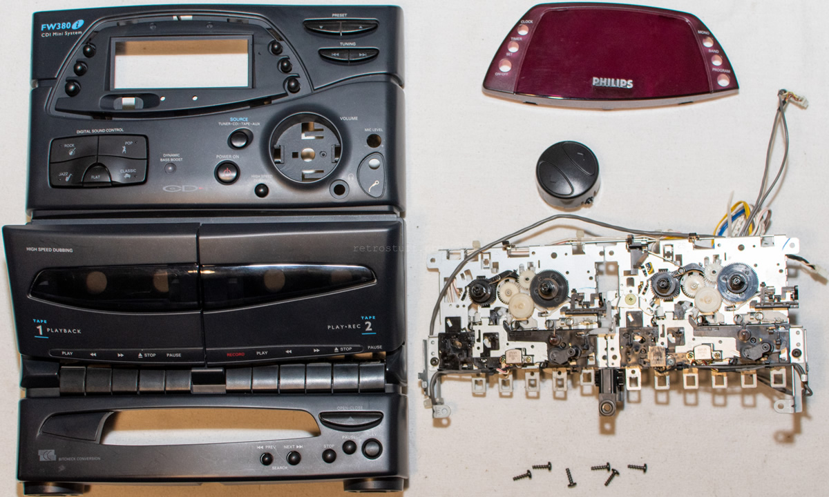
In this article I will show you how I carried out the disassembly and basic cleaning last year. I will follow up about diagnosis, repair and possibly modifications at a later point. The exact model/version I’m taking apart here is an FW380i/20 – which means that a 22ER9956/20 DVC mini cartridge was installed at the factory.
Disassembly
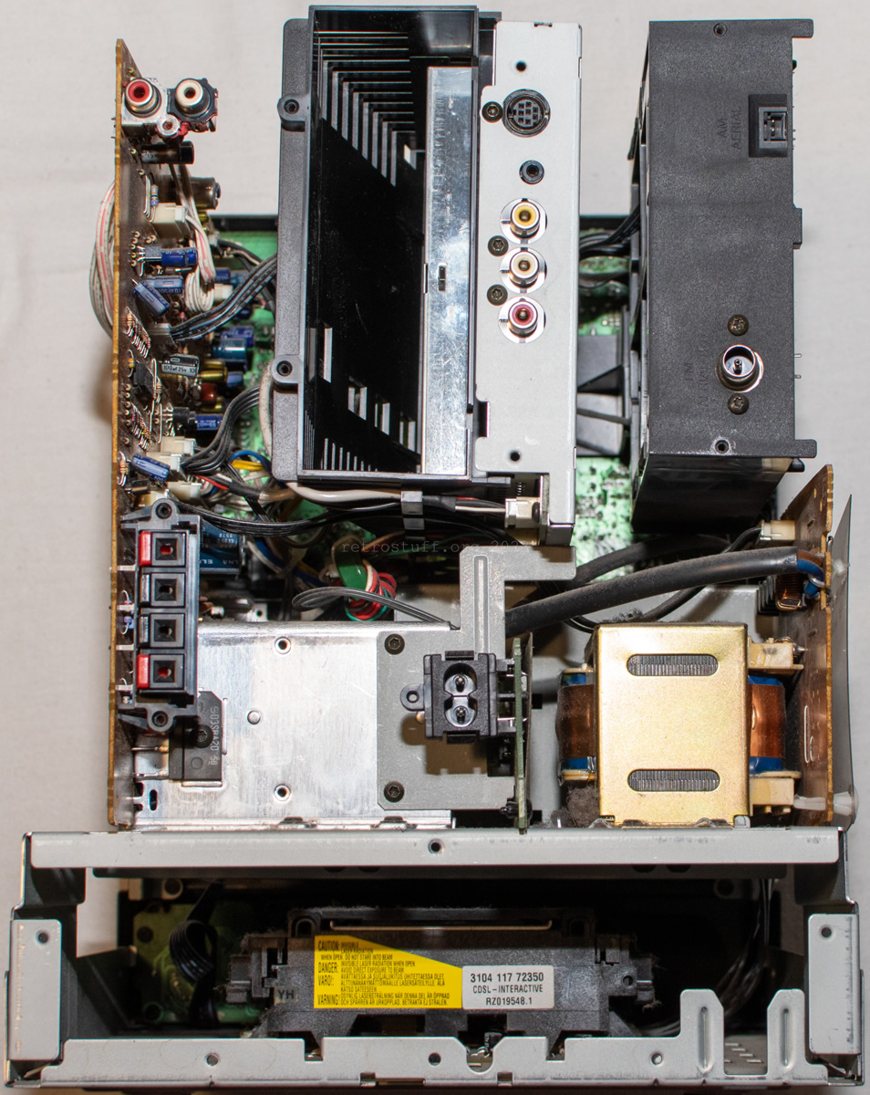
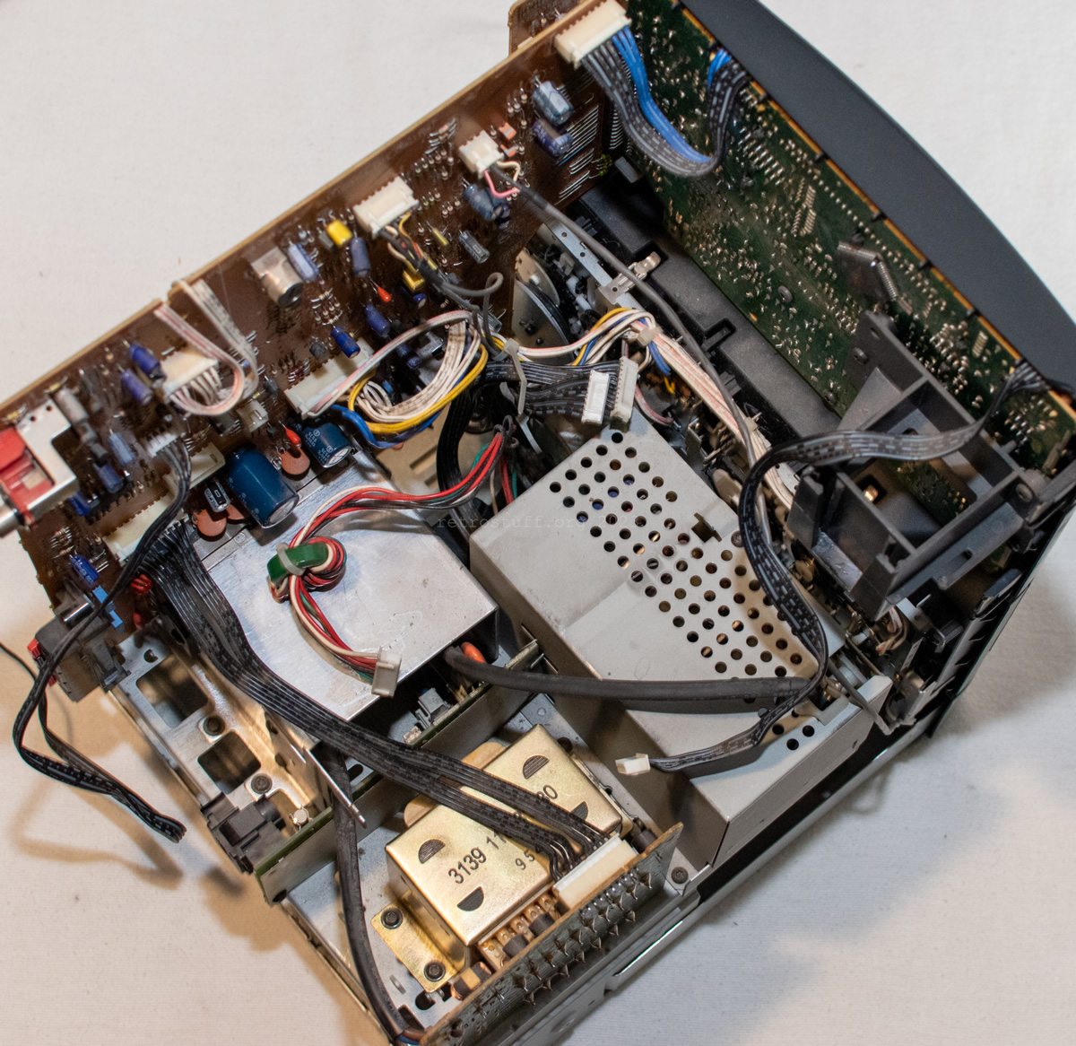
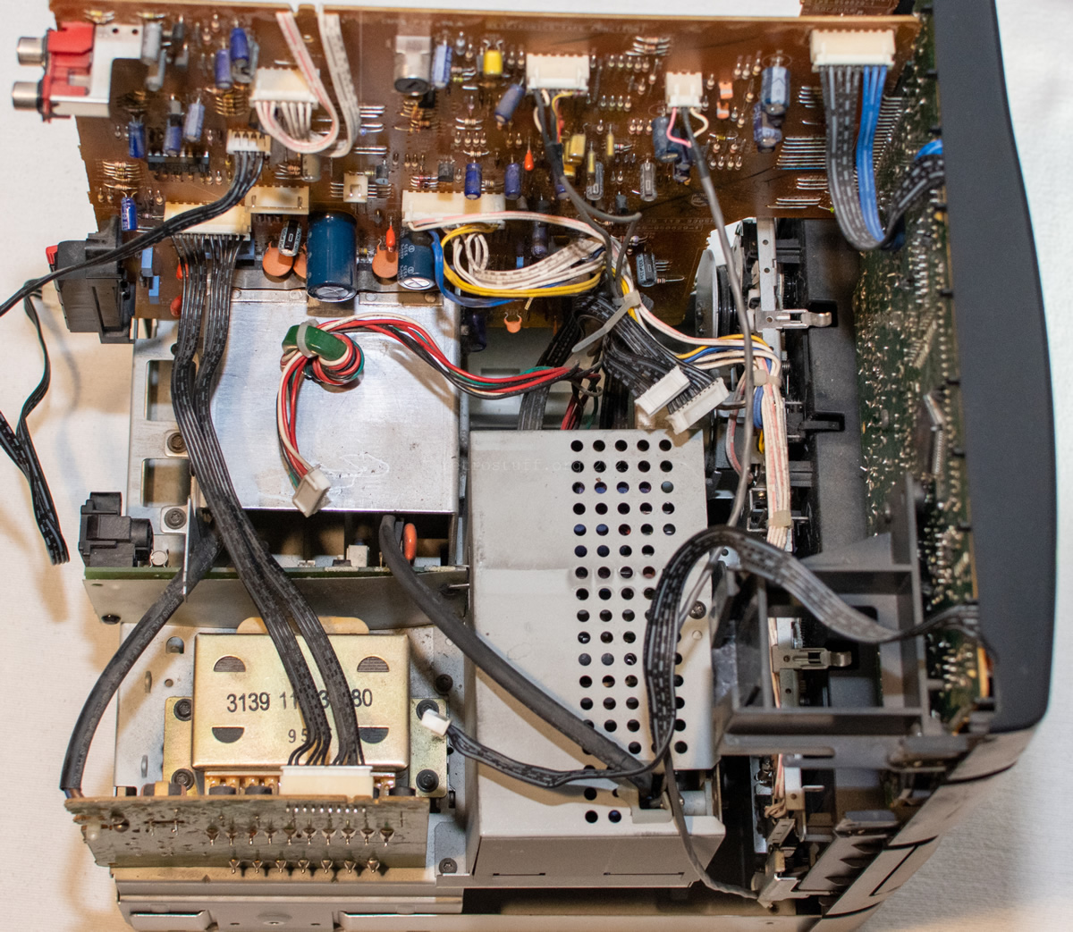
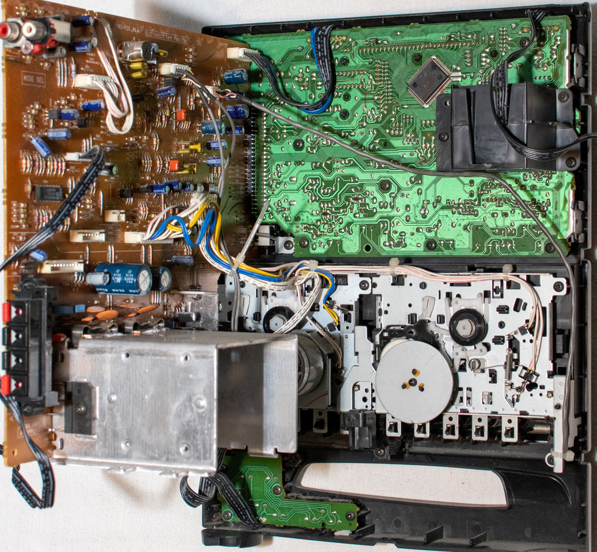
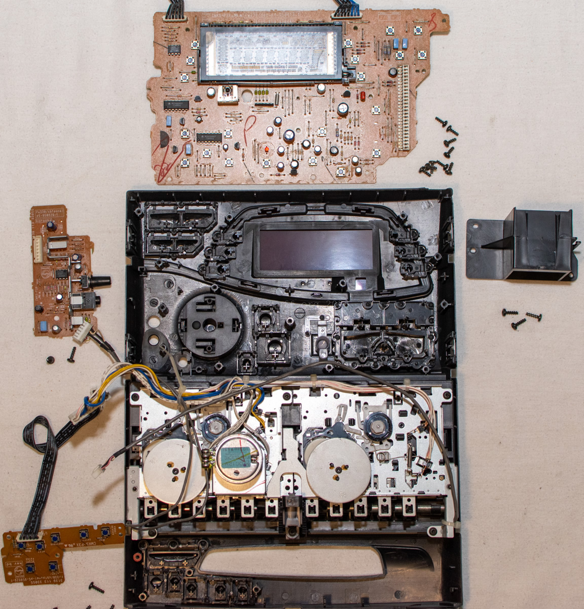
It became very clear after removing the housing: This CD-i model guarantees hours of disassembly fun.

The service manual was not very helpful in this respect. There are several exploded views for individual parts such as cassette decks and CD loader, but only one for the whole unit. Service manuals for similar models (e.g. Philips FW330 and FW46/56) gave me some additional information on which parts to remove and in which order.
Also, the FW380i service manual and PCB markings aren’t very consistent in the naming of the various parts, so I will therefore try to mention all relevant namings at the beginning of each section.
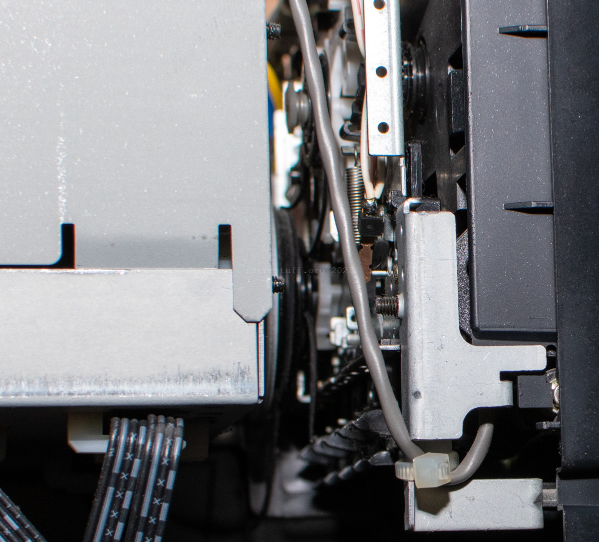
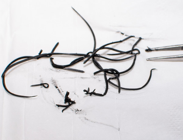
At least I was able to quickly find out why the cassette decks were no longer working. The belts were already rotten and hanging loose, so I grabbed everything I could reach and removed it from both sides. There was still more stuck to the mechanism, but more on that later.
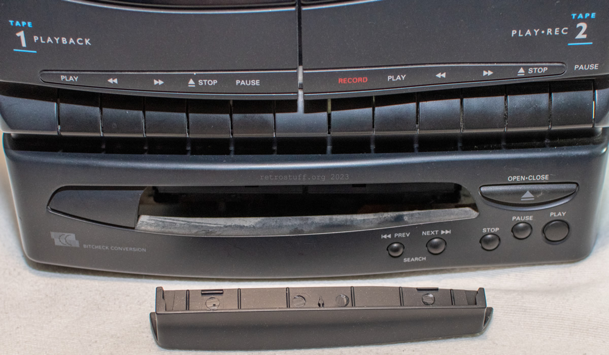
Before continuing with the disassembly, I switched on the unit one last time to eject the CD tray and remove the bezel. I then closed the tray again to make disassembly easier later.
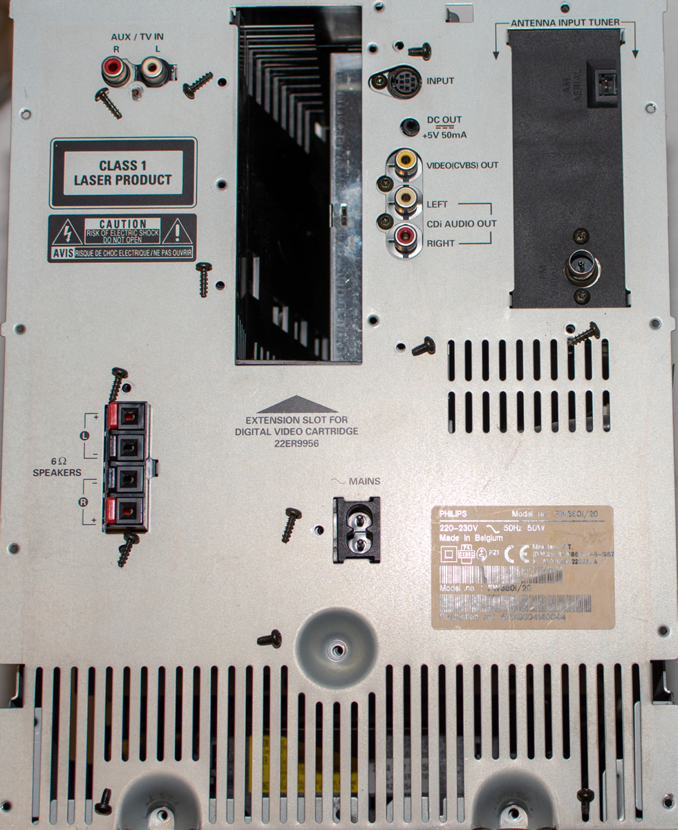
So that there are no problems later when reassembling, these are the positions of the two different types of screws on the back (the DVC cover with three silver screws has already been removed):
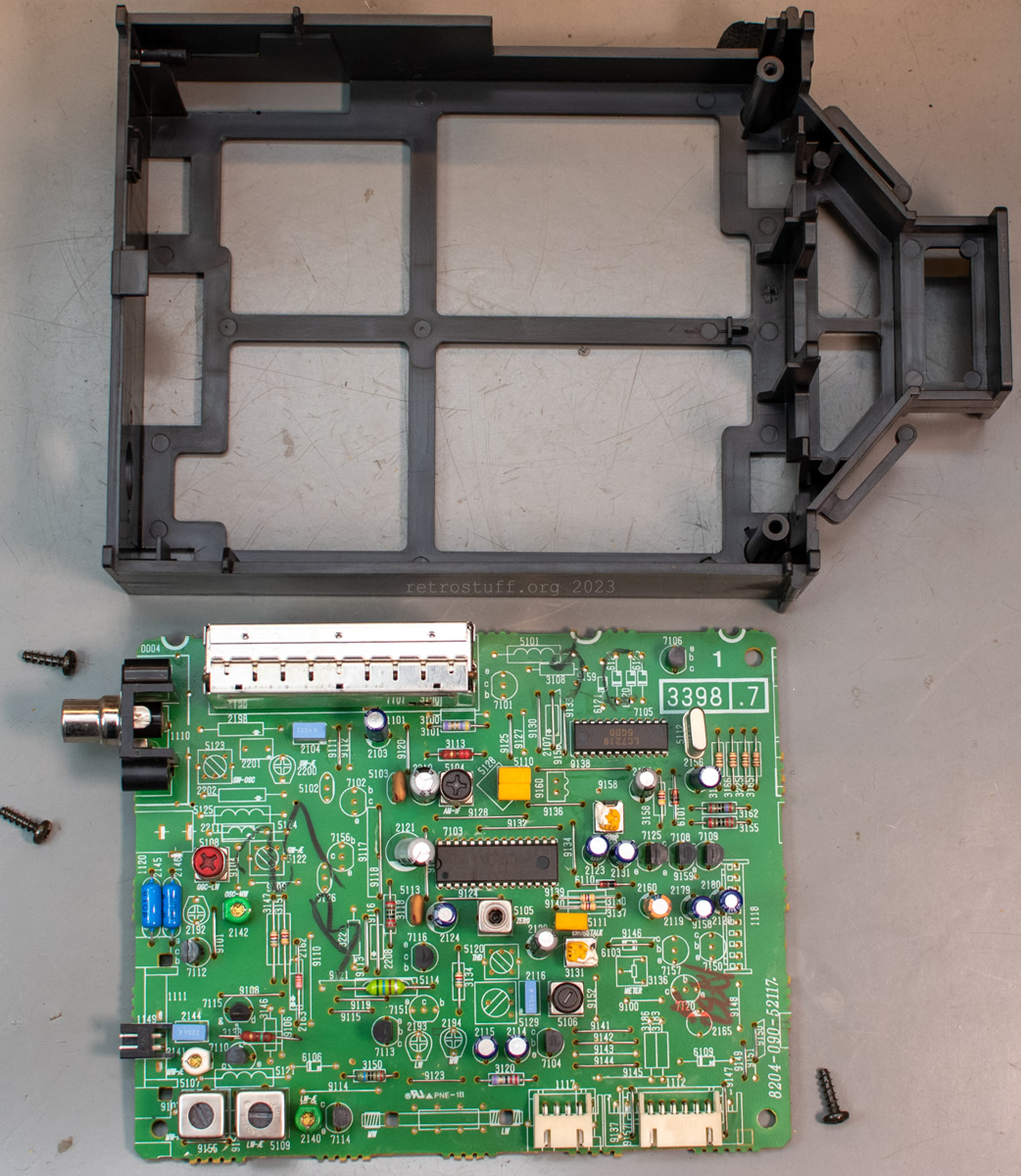
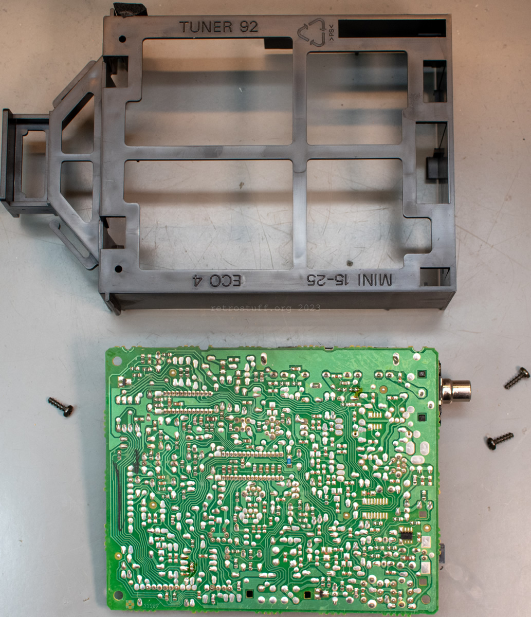
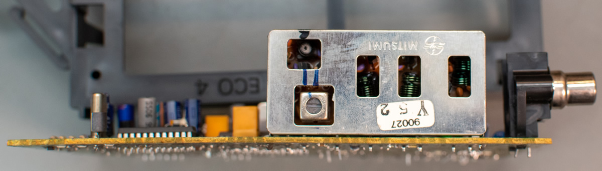
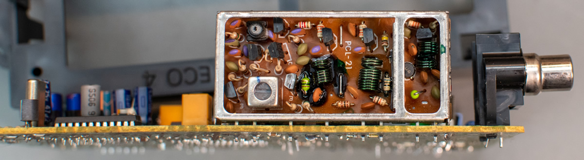
Tuner
aka (T) – TUNER PANEL / TUNER / TUNER MINI 94
Once the back cover was removed, I went to the next easily accessible part: the Tuner.
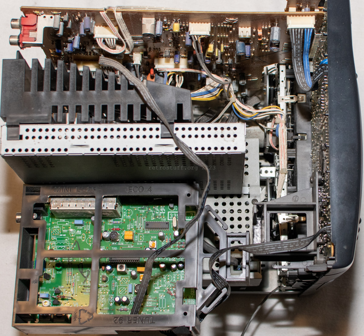
Since it was working fine, I only cleaned it briefly for the detailed photos:
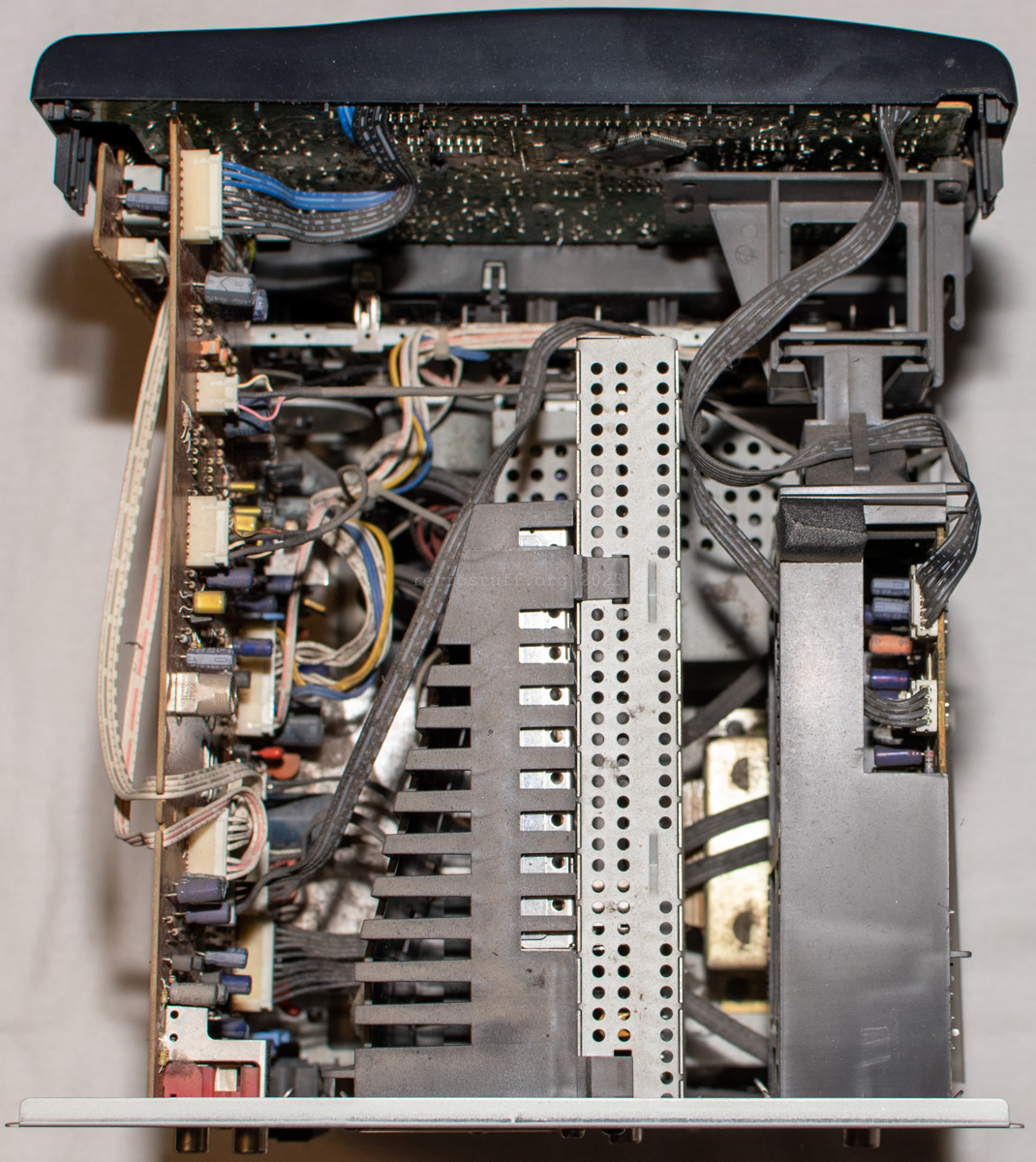
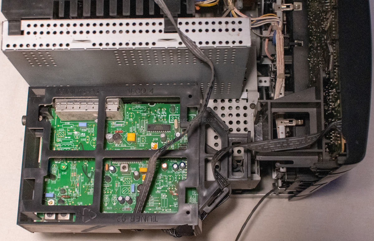
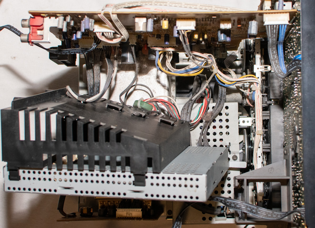
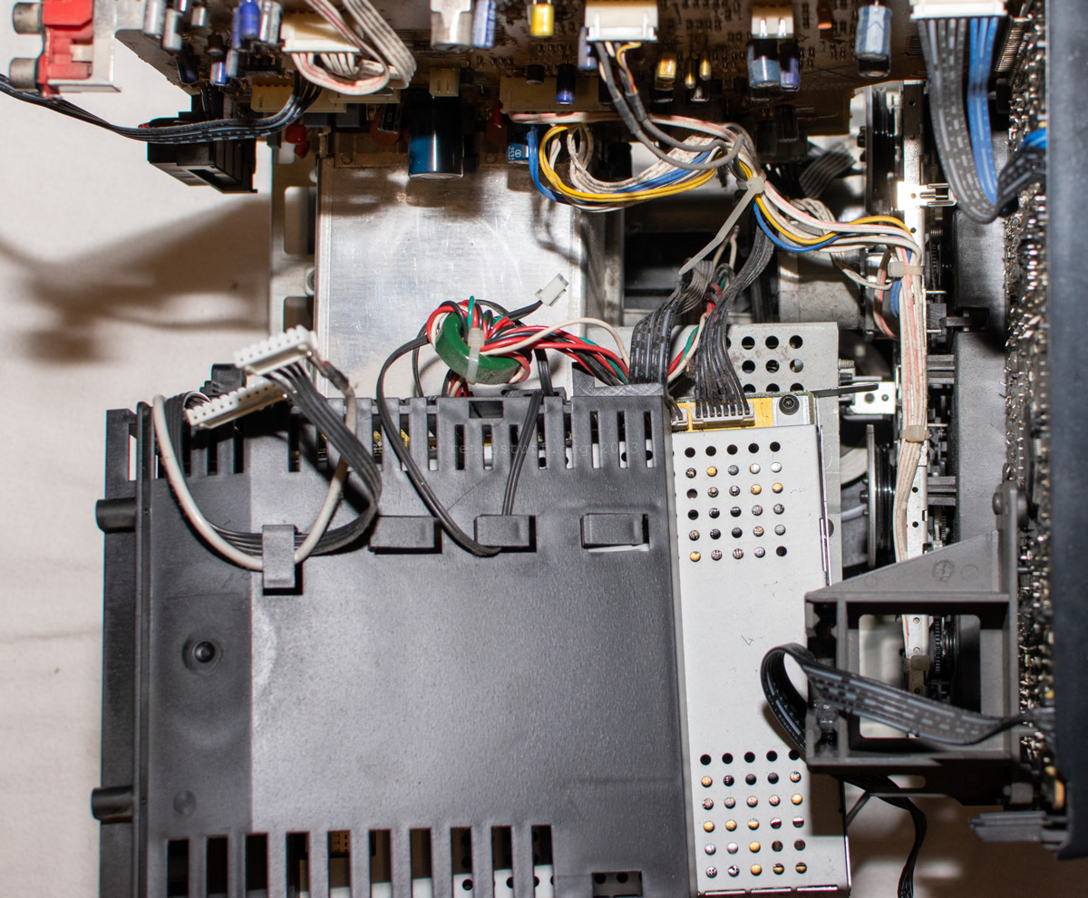
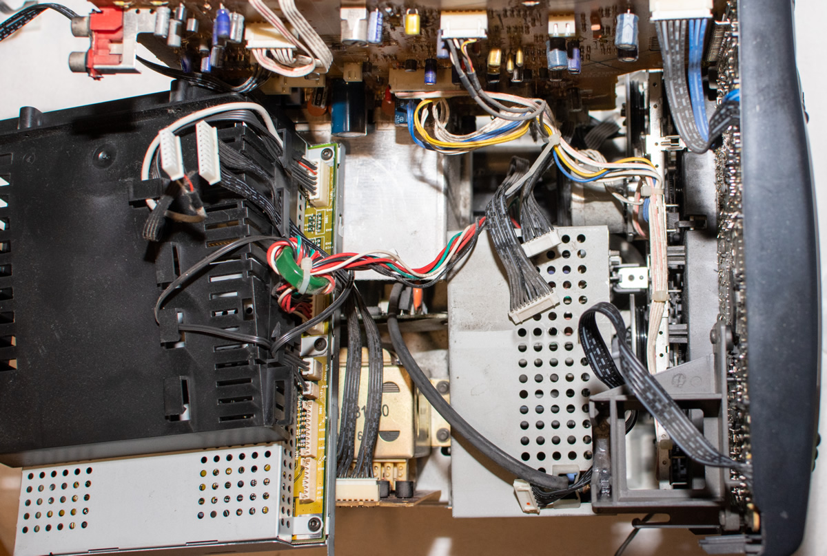
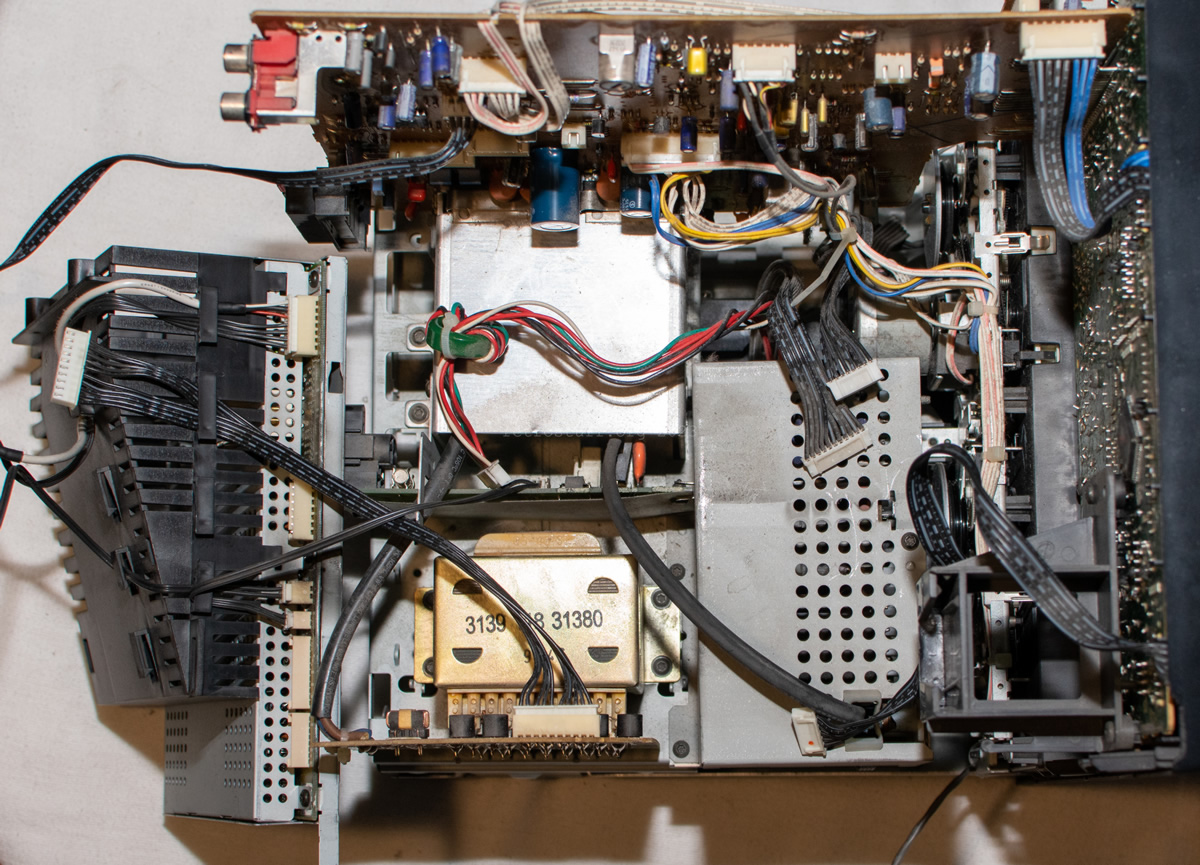
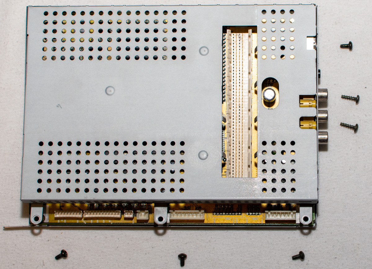
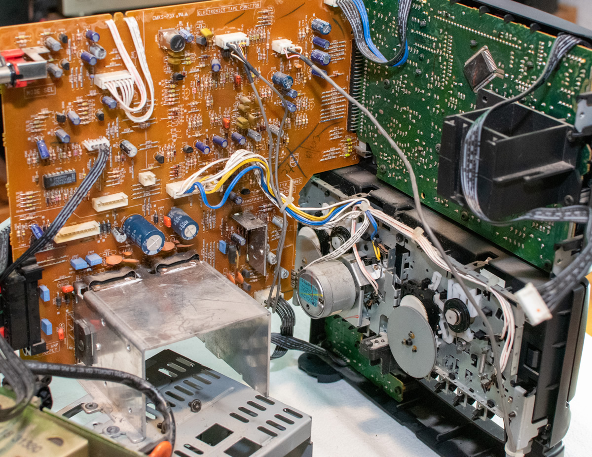
CD-i mainboard
aka (M) – MAIN PANEL / CDI-MAIN / MONO FW380
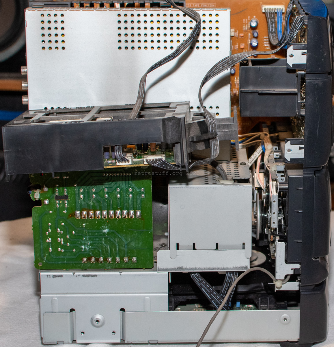
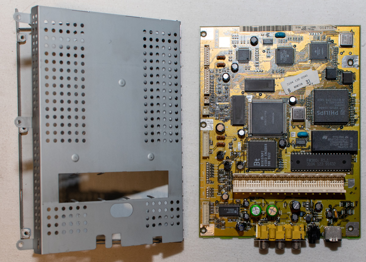
The next accessible part is the CD-i mainboard in a metal case with the DVC cage sitting on top of it. Numerous cables come and go from the mainboard. These photos will surely help to get everything back together:
And finally I reached the “MONO FW380” board. It’s tiny. There will be more photos and details about it in a follow-up article.
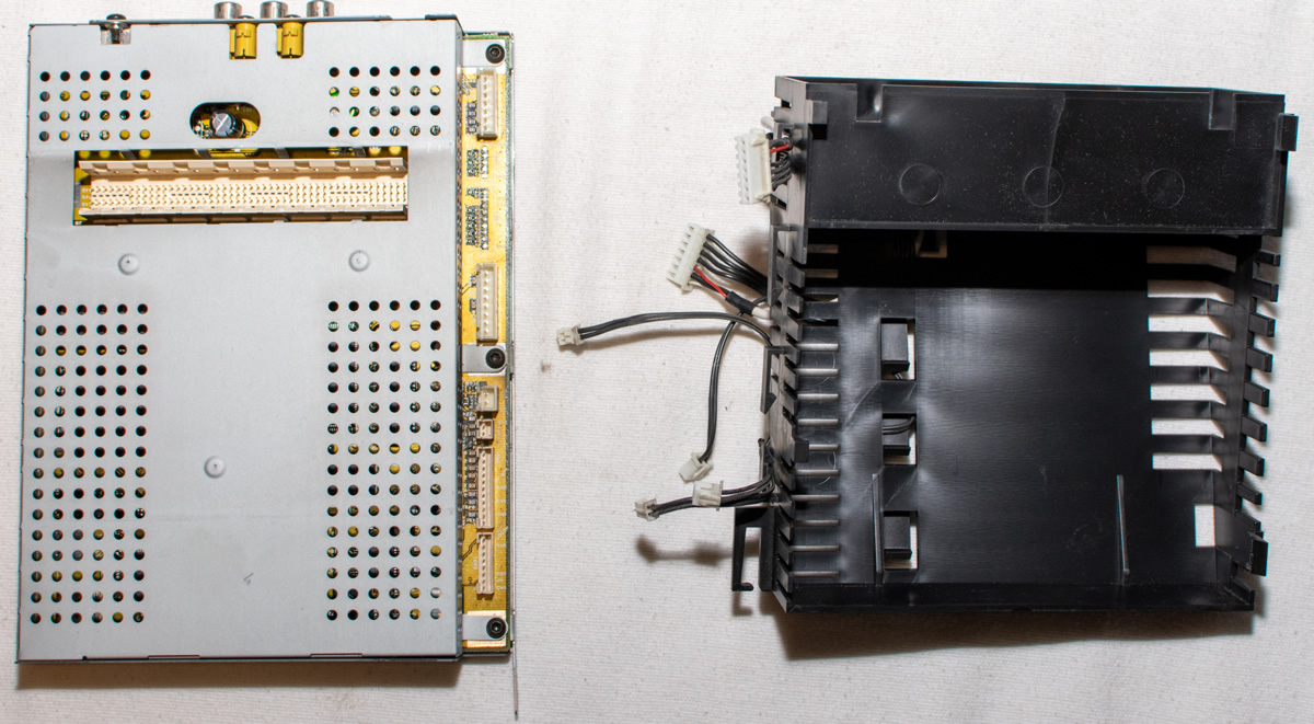
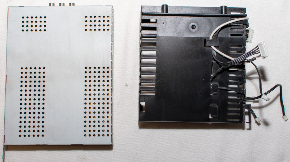
Like the DVCs, it comes in a metal case that can only be opened and closed a few times until it breaks. The case is now stored half-open in a safe place until the repairs are completed.
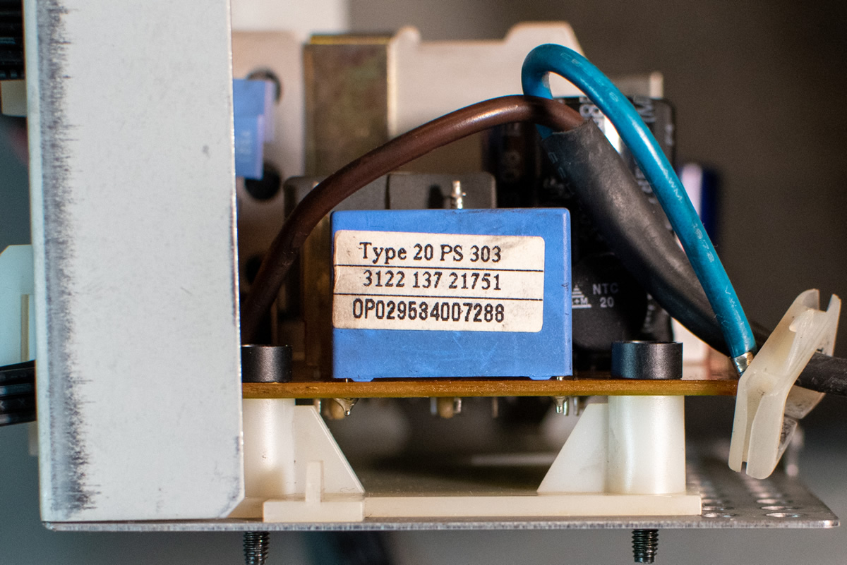
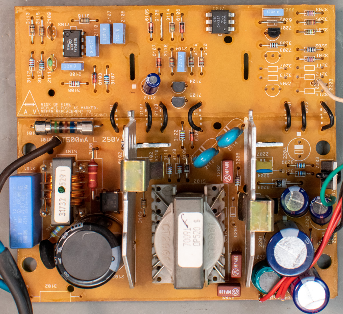
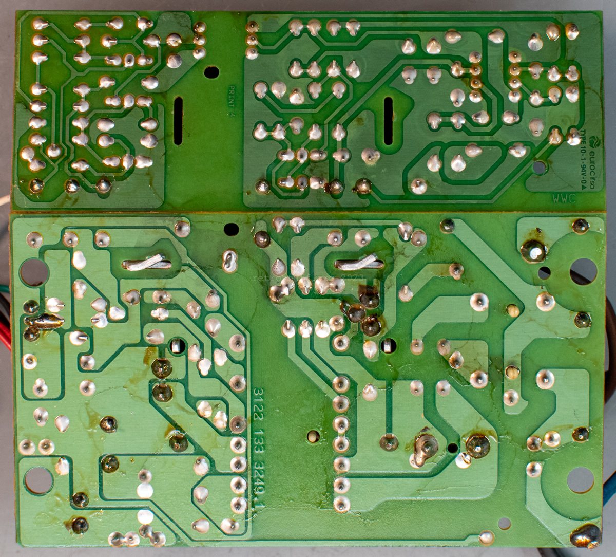
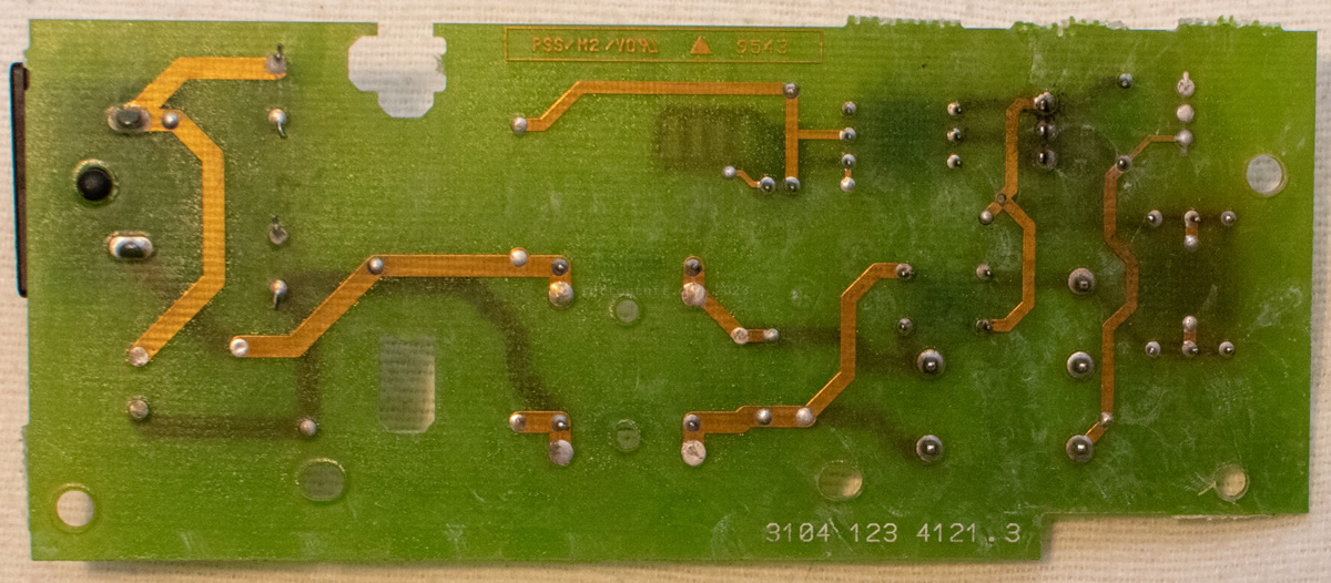
CD-i power supply
aka (P) – POWER SUPPLY / PSU CDI / CDI PSU / 20PS303
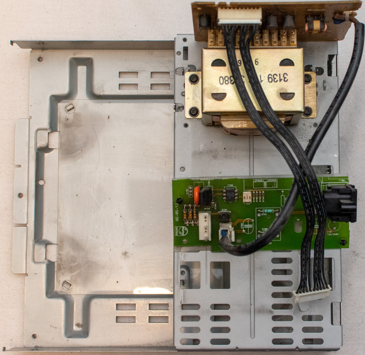
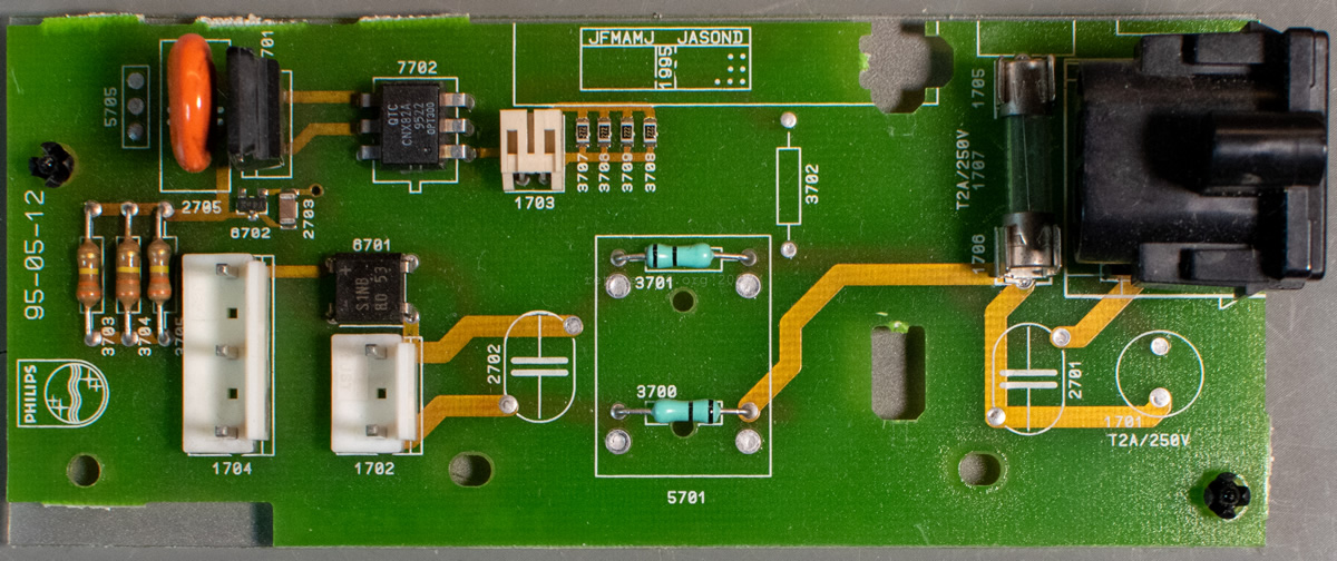
With the CD-i mainboard out of the way, I moved on to loosen the switch board and to remove the CD-i power supply.
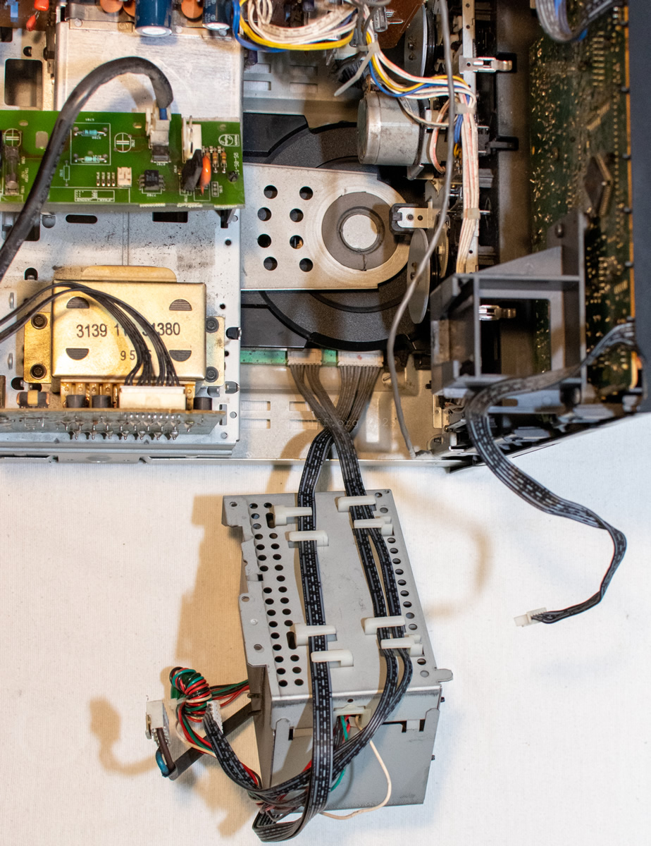
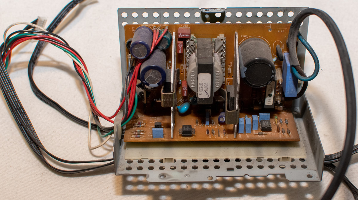
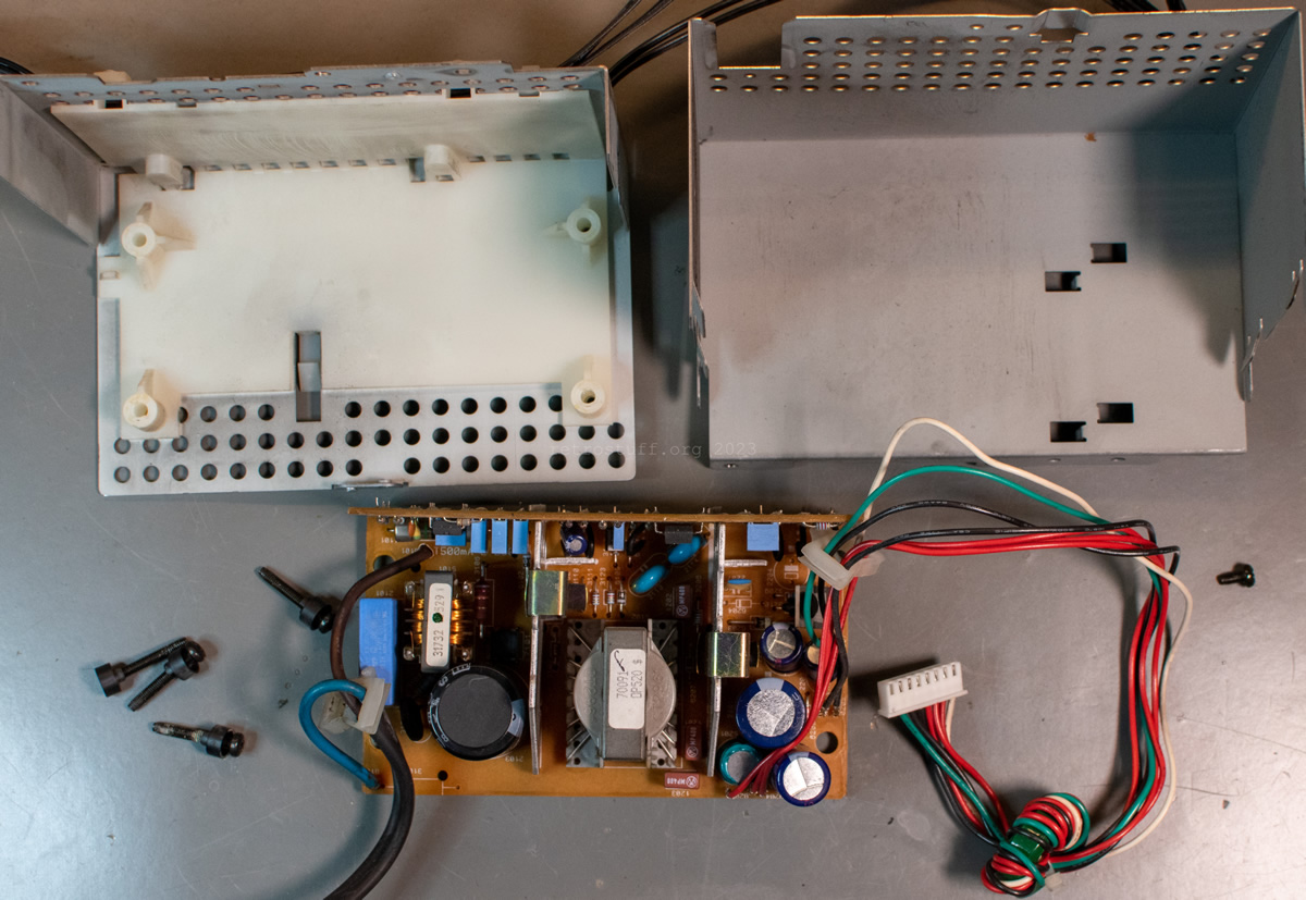
This is the CD-i power supply 20PS303 in its full glory, after having been unfolded and cleaned:
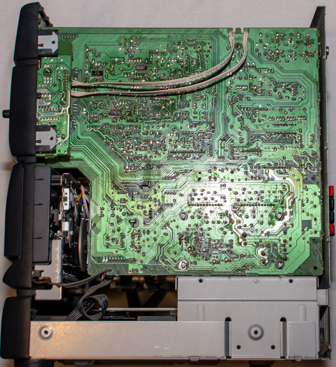
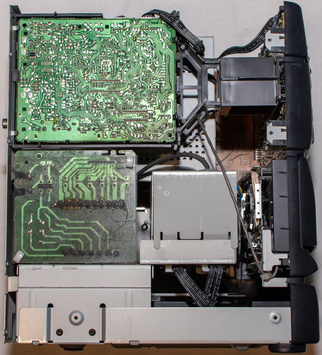
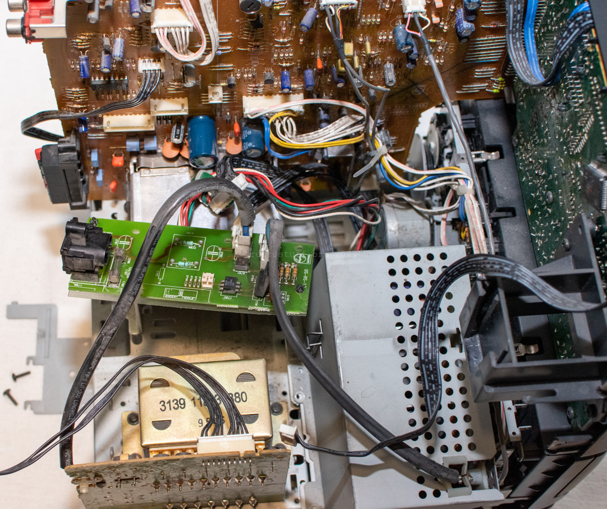
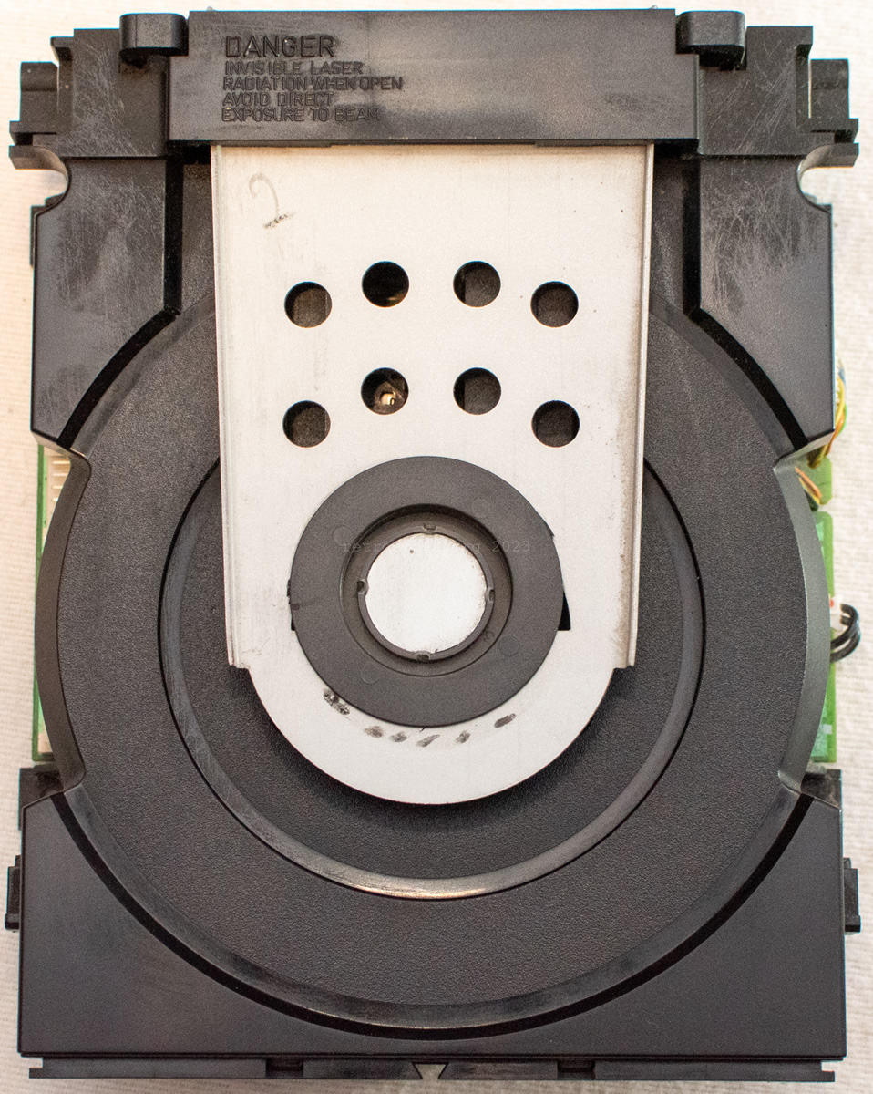
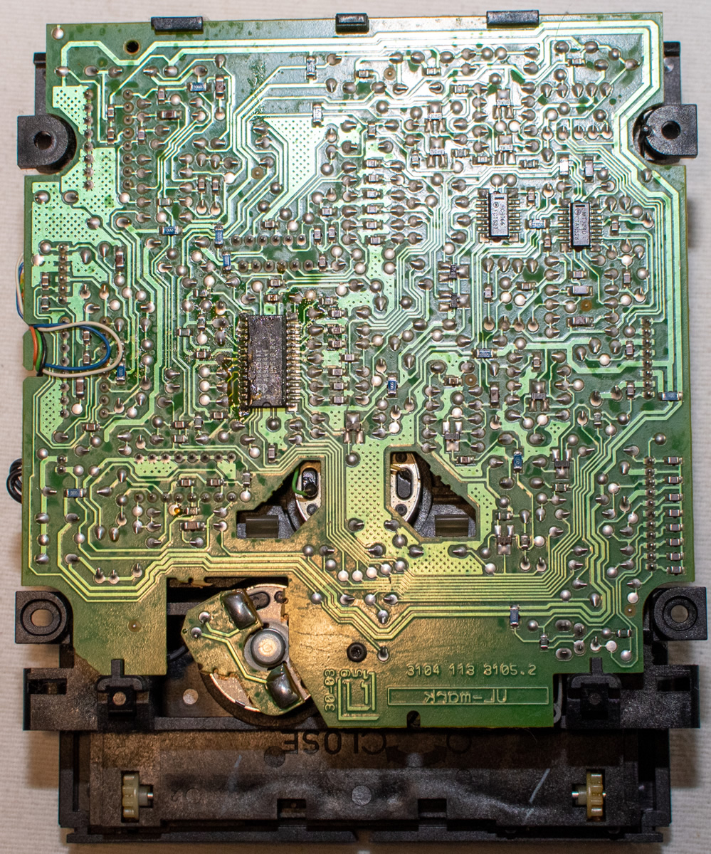
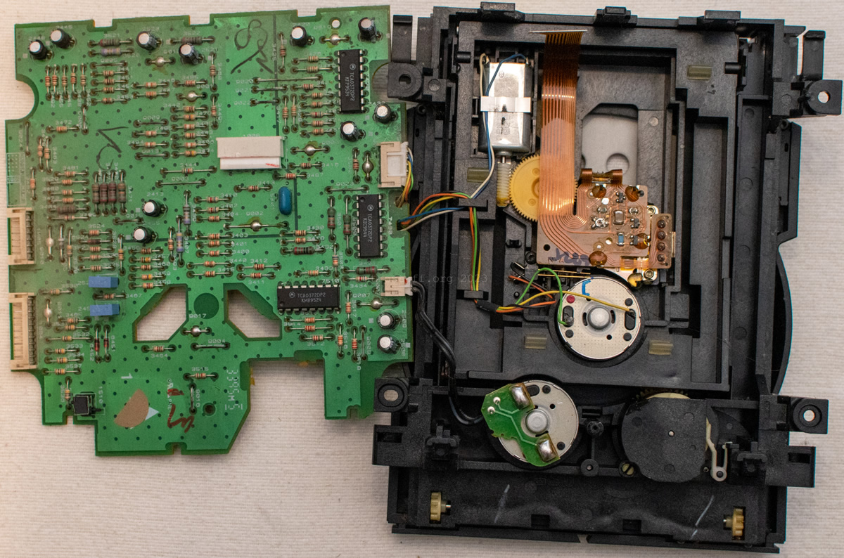
CD Short Loader and servo panel
aka (R) – TRAY & CDM and (S) – SERVO PANEL / SERVO / SERVO BOARD
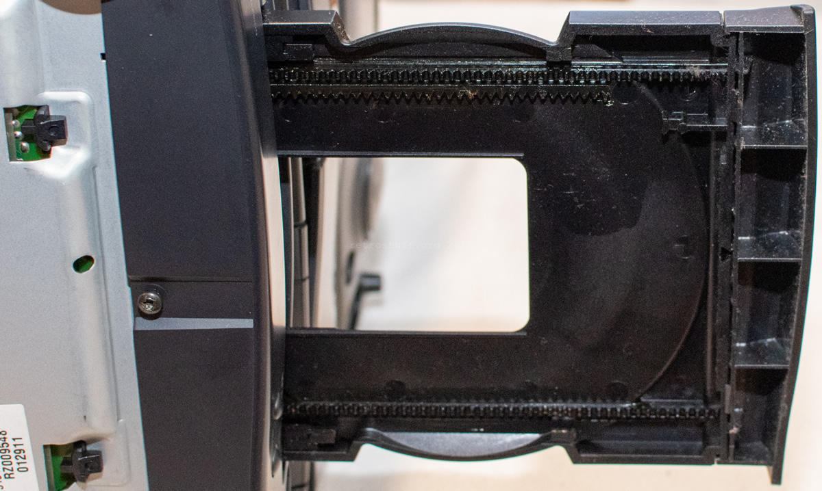
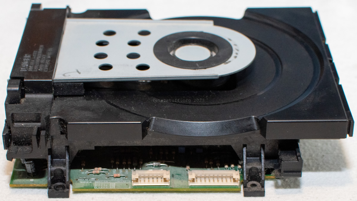
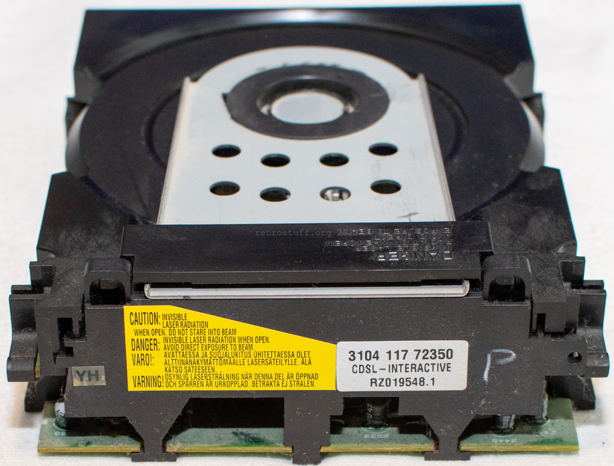
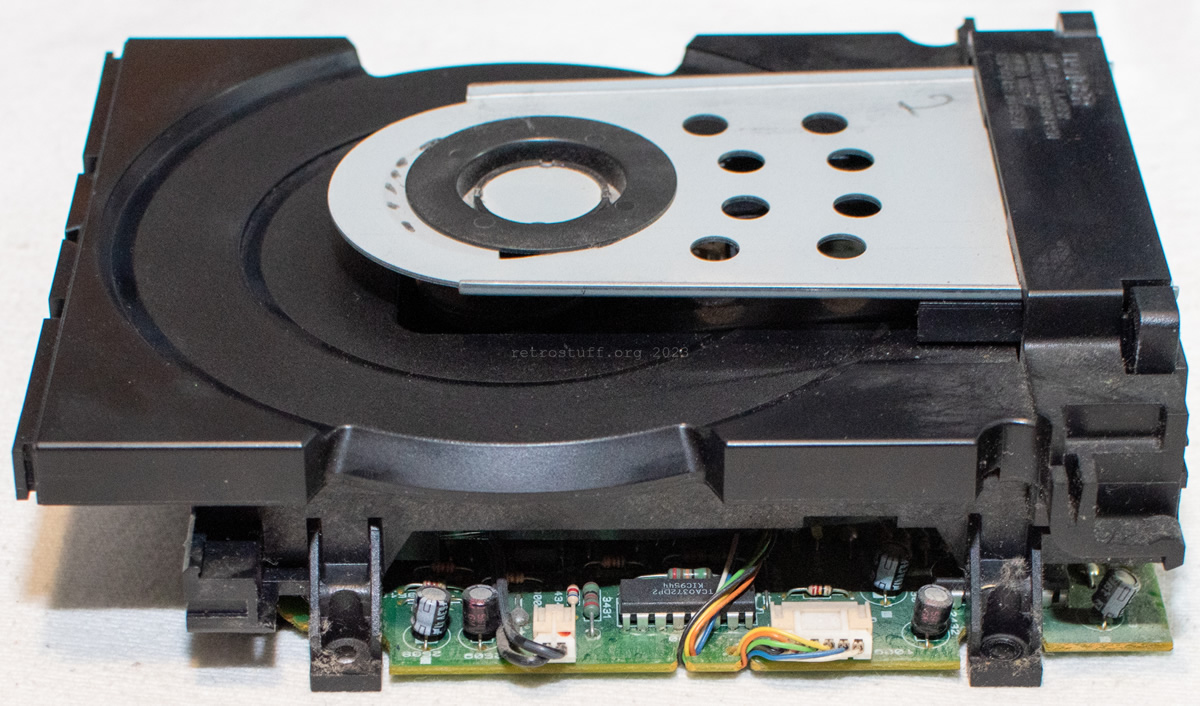
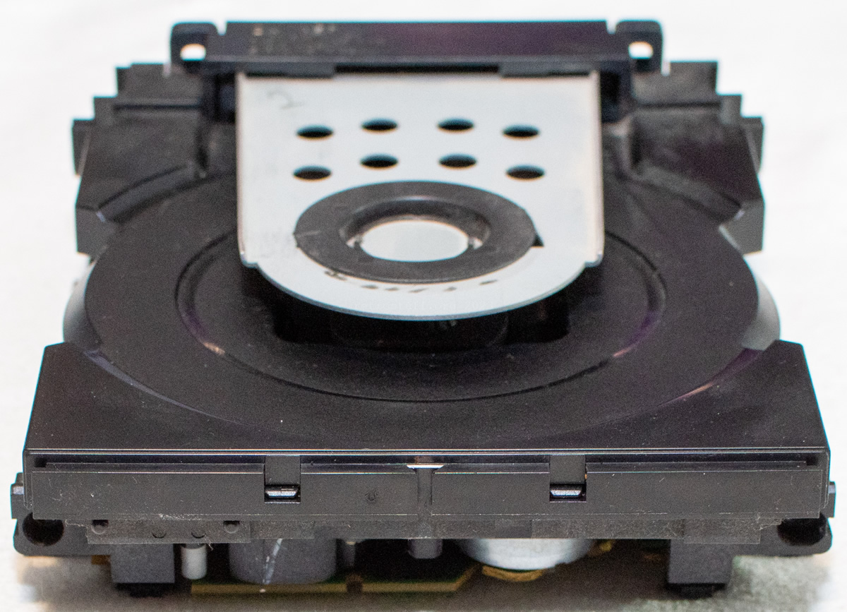
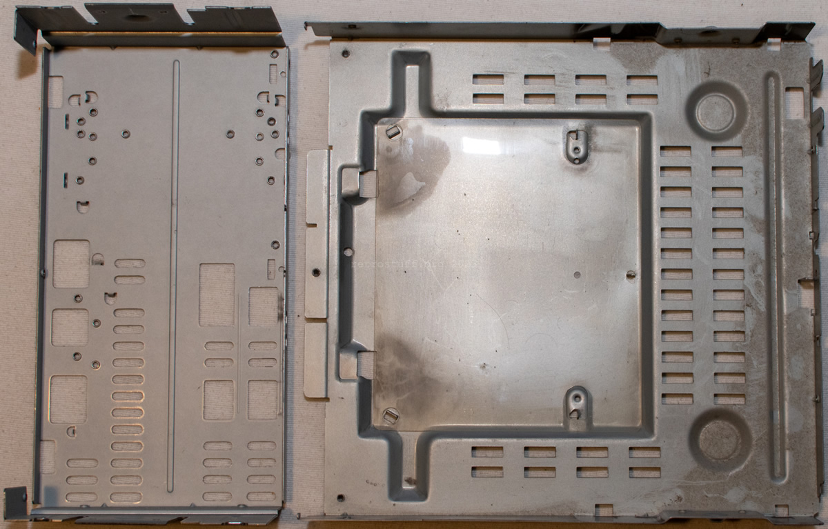
To continue with the disassembly, I separated the entire front and Combi board from the chassis to finally reach the dusty CD Short Loader.
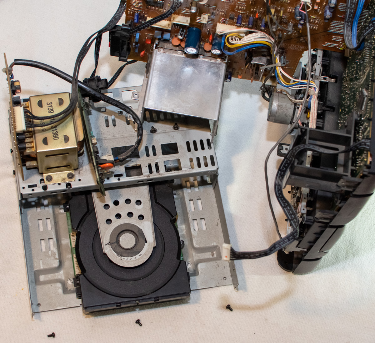
The CD Short Loader is not used in any other CD-i player. The servo section is also not on the CD-i mainboard, but on a separate board which is connected with two ribbon cables. The CD mechanism, on the other hand, is an old friend: a CDM 12.1.
Combi board
aka (C) – COMBI PANEL / COMBI BOARD
Once all the CD-i parts were out of the way, I separated the Combi board from the front. It appears that we have two smokers on it, which will need to be investigated further at a later date.

Front board
aka (D) – DISPLAY PANEL / FRONT BOARD
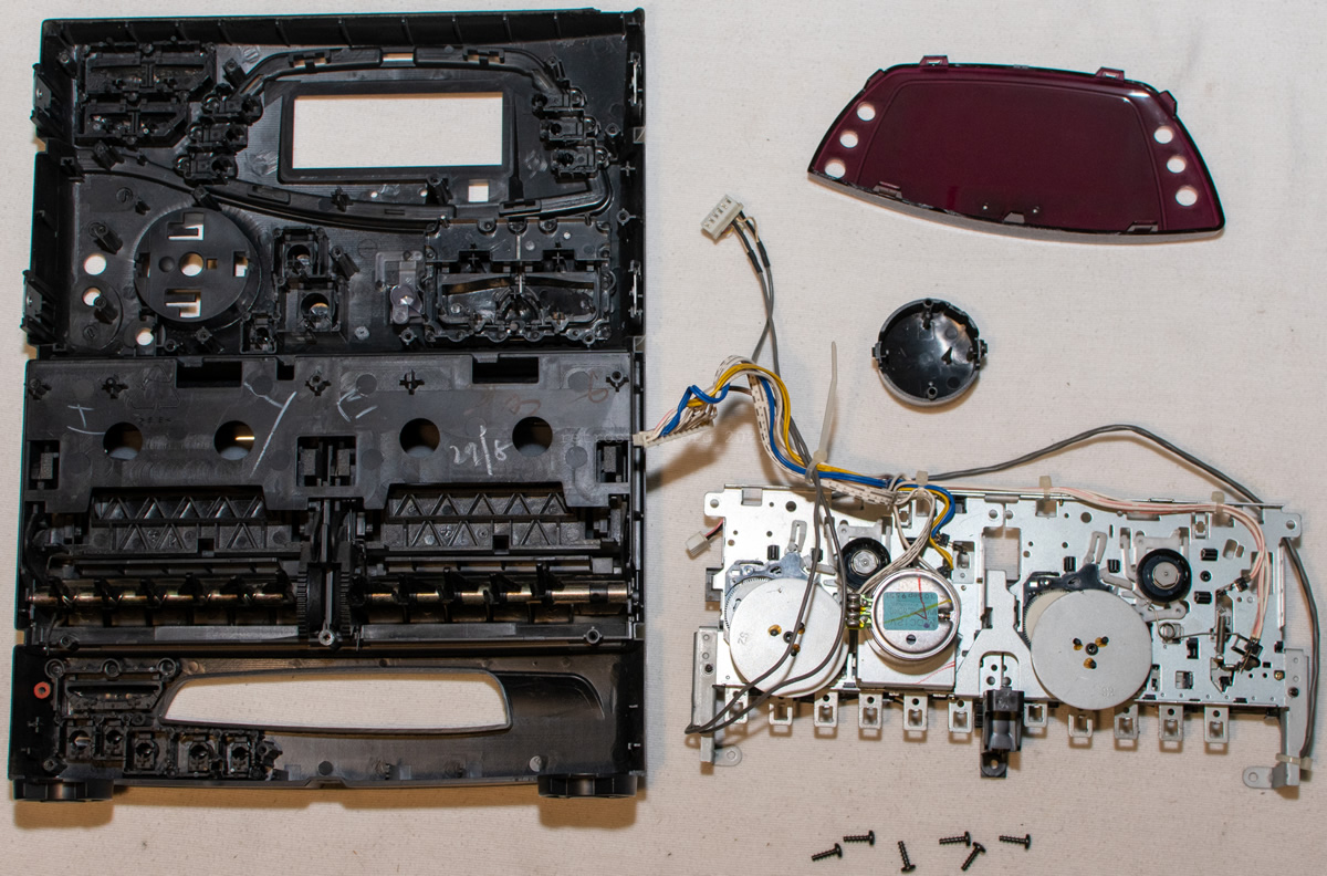
A lot had to be removed from the front:
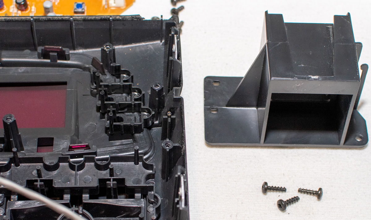
The piece of plastic that held the Tuner and the Front board:
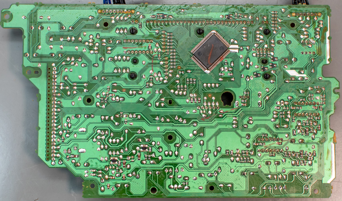
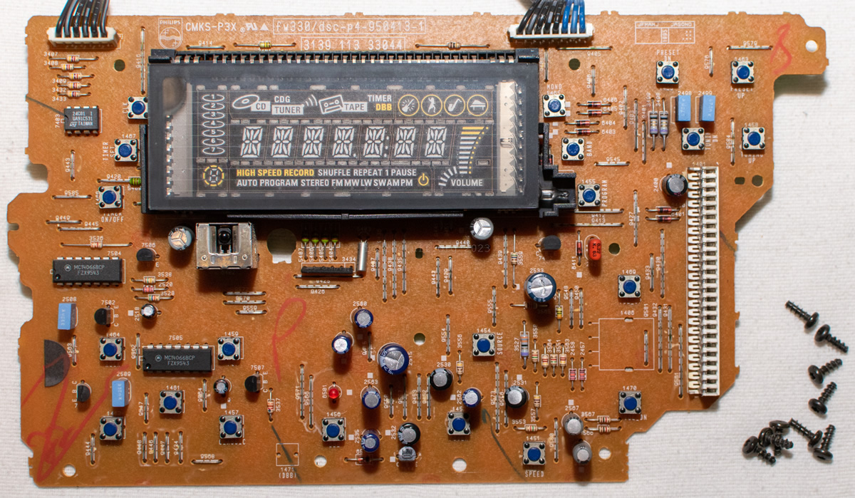
The brain of the Front board (and the entire FW part) is an 8-bit Toshiba TMP87CM70AF MCU with VFT driver (marking: T FW380I.1 | 87CM70AFG301 | JAPAN 9531HB).
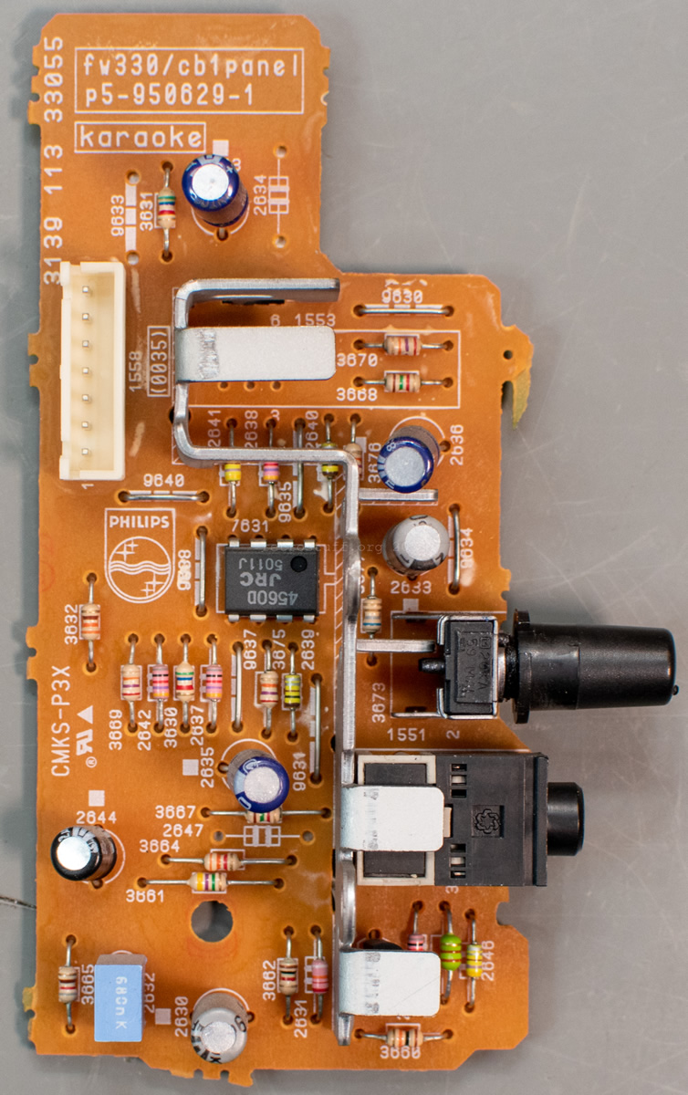
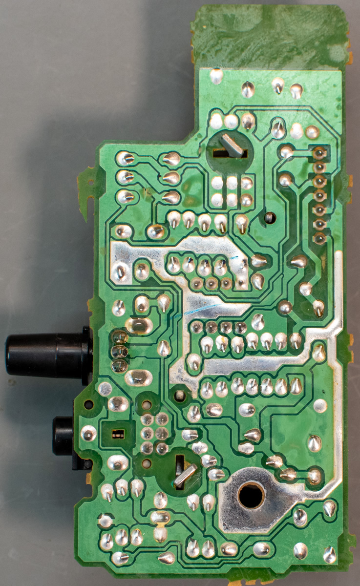
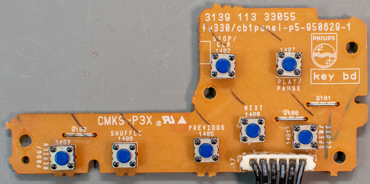
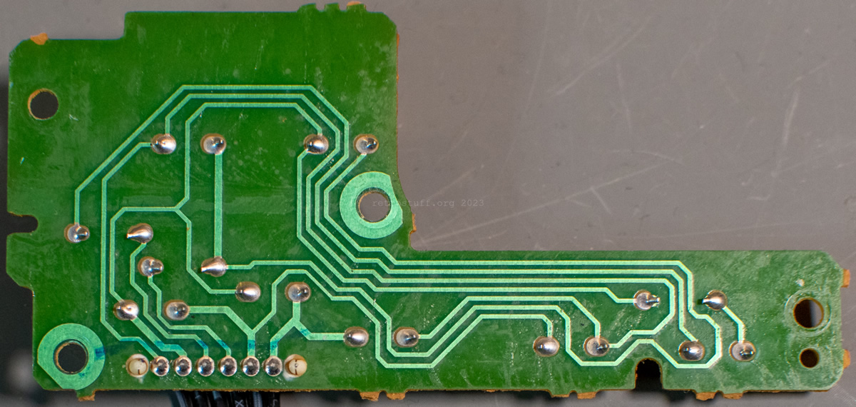
Karaoke and CDKEY boards
aka (K) – KARAOKE PANEL / Karaoke Board and (Y) – KNOB UNIT II / KEY CONTROL? / CDKEY BOARD
A quick look at the Karaoke and CDKEY boards:
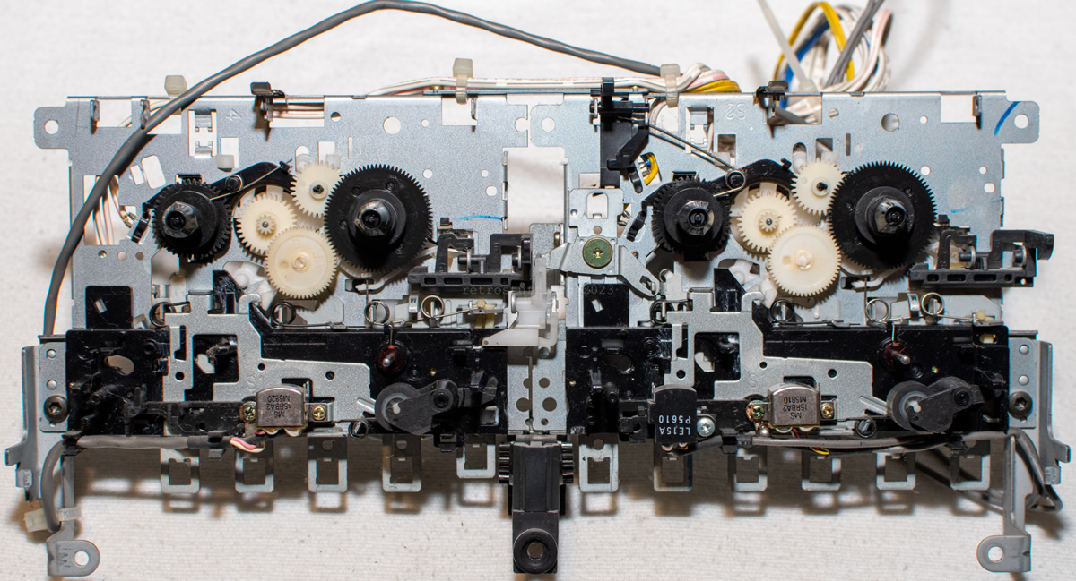
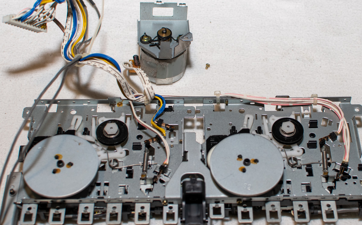
Tape drive
aka (A) – TAPE DRIVE / TAPE
These are the last parts I removed from the front. The cassette deck compartments and controls will remain and be cleaned from the inside, and the cassette mechanisms will undergo a thorough dust and goo removal at a later date.
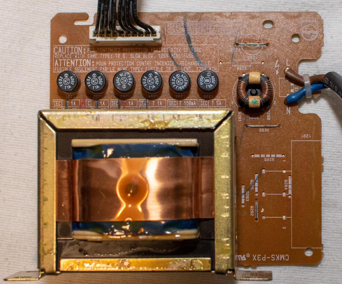
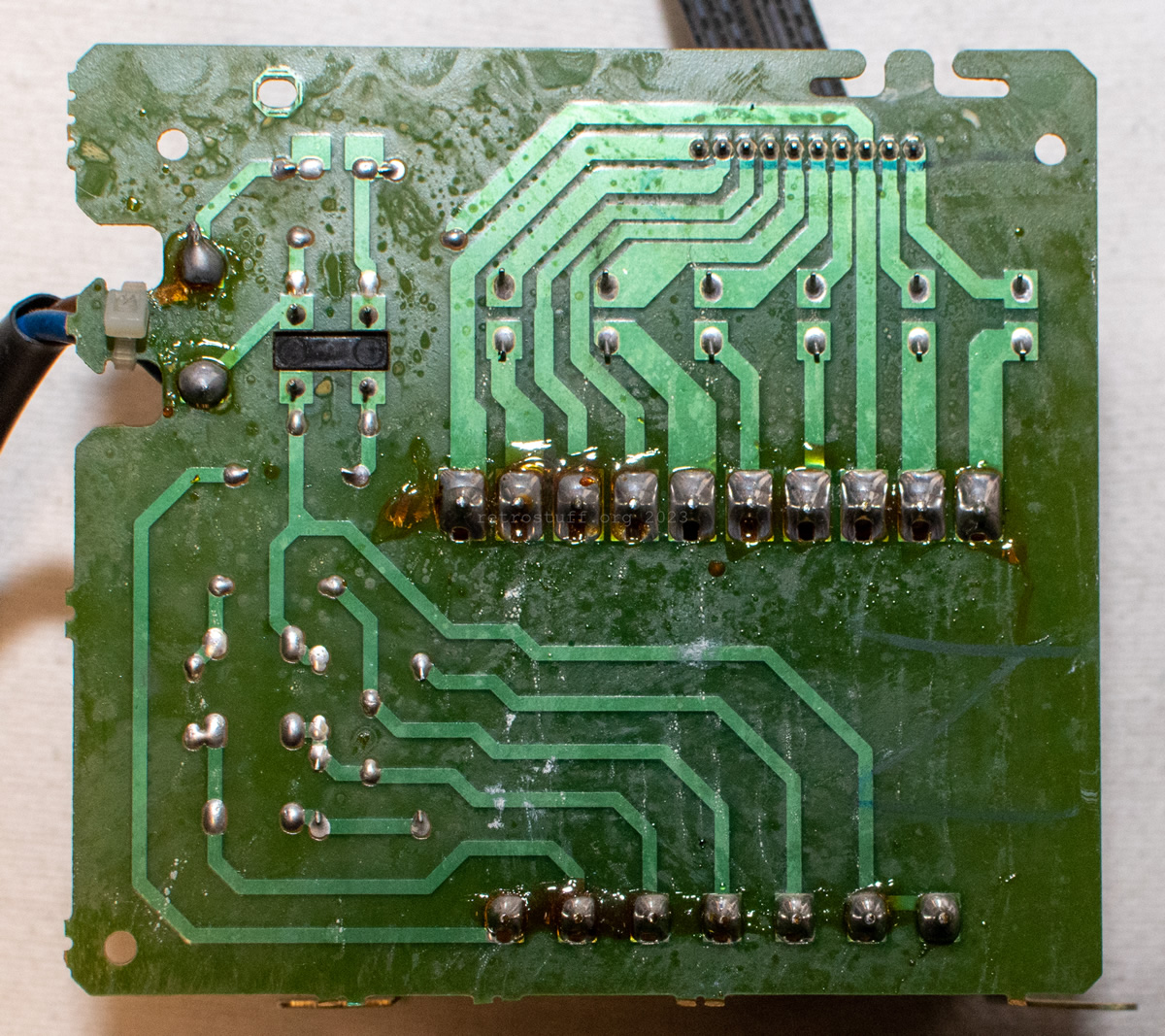
Switch board and transformer
aka (W) – SWITCH PANEL / ON/OFF CIRCUIT – EMI FILTER / MAINS INPUT and (Z) – TRANSFO PANEL / TRAFO BOARD / TRANSFORMER / TRANSFORMER BOARD
And now for the last part of the disassembly:
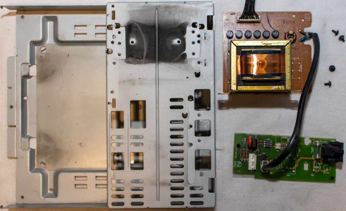
This is the switch board (which switches the CD-i and FW parts on and off) and the transformer (which supplies the power for the FW part):
What’s next?
As already mentioned, there will be one or more follow-up articles on troubleshooting and repair for the FW part (cassette decks, Combi board) and the CD-i part (Timekeeper, CDM, servo board). The latter has already given me some headaches. I might also figure out some modifications then.
2 thoughts on “Philips FW380i Mini System Repair Part 1”