
A spontaneous article about the NEC PC-FXGA: The PC-FX Game Accelerator Board for PC-98 and DOS/V. It emerged from the search for a replacement breakout box for the PC-FXGA DOS/V card in the PC-FX Fan Club Discord server. The details of the breakout box are in the second half of the article, and before that some information and photos.
There are already many resources about PC-FX(GA) (see list at the end of this article), so I won’t go into too much detail here. Basically, it’s a PC-FX on a card for your PC, with a special feature. Game Accelerator means that it also contains the 3D chip Huc6273 (Aurora) that is not present in the normal PC-FX. There are two versions of these cards: PC-FXGA, a C-Bus card for use with NEC PC-9800 series computers and PC-FXGA DOS/V, an ISA card for use with IBM PC-compatible computers running DOS/V.
PC-FXボード / FX-98IF
For the sake of completeness, it should be mentioned that there is a third card, which is actually the first one made. Unfortunately, I don’t own it yet and therefore can’t show any photos at this time.
The PC-FXボード (FX-98IF) is also a C-Bus card, but it lacks the 3D chip and is therefore just a normal PC-FX on a card. There are also some other differences to the PC-FXGA cards, which are explained here (in Japanese).
PC-FXGA / PC-FXGA(98)
This is quite a package that’ll get you started playing and even programming PC-FX(GA) titles on your PC-98:
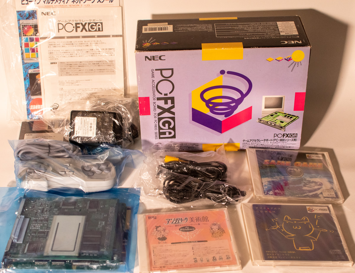
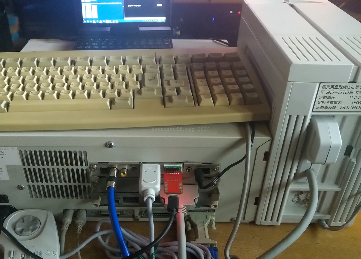
I didn’t use it for programming, but for a final test of the PCFX Uploader RP2040 Device earlier this year. The photo shows my PC-9821Xe/U7W (which uses my PC-FX as ODD via FX-SCSI) with PC-FXGA and the PCFX Uploader.
A closer look at the two circuit boards, which are plugged into each other. The slot bracket on the left-hand side provides sufficient space for all the required connections and an additional socket for the external power supply unit.
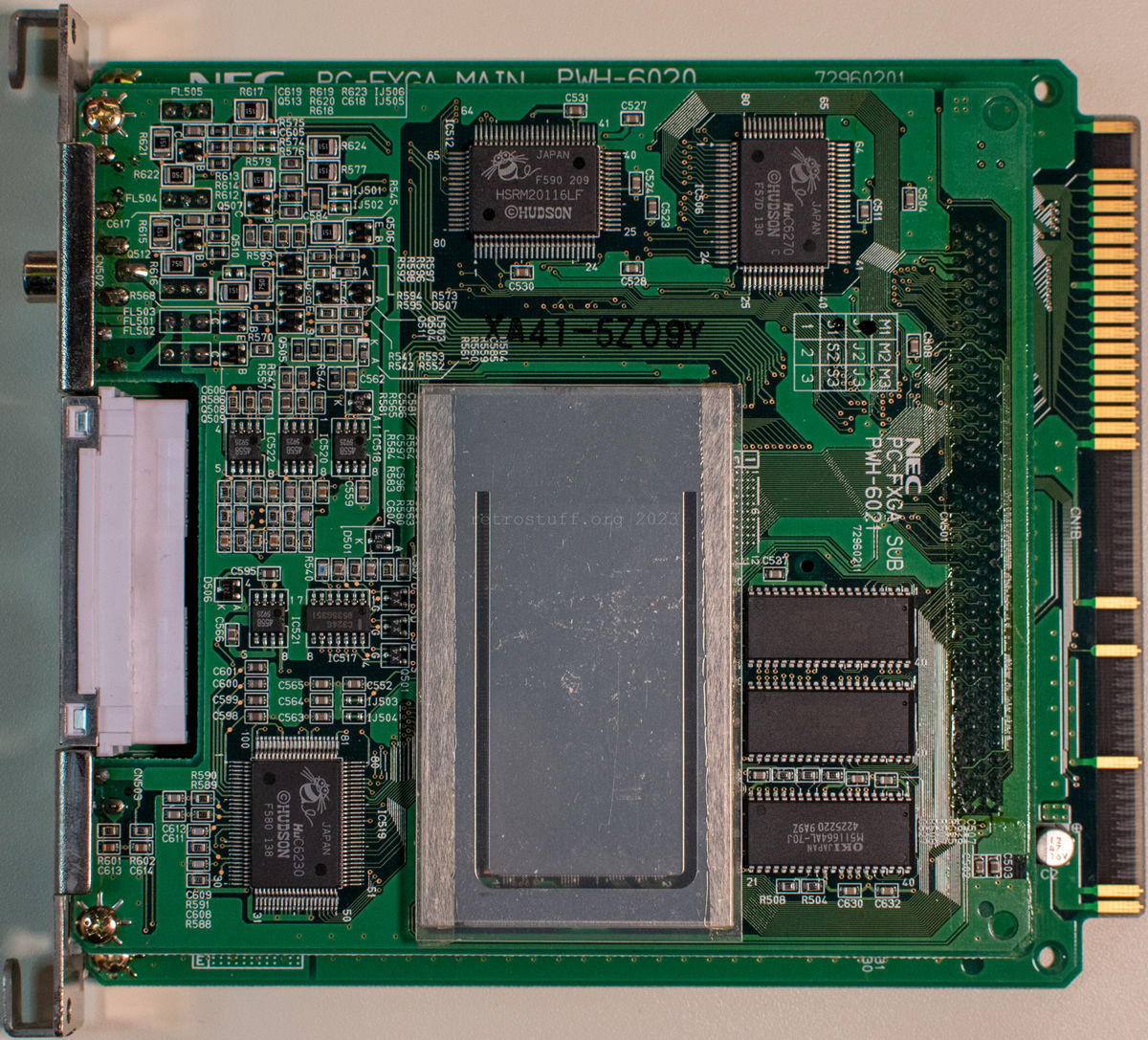
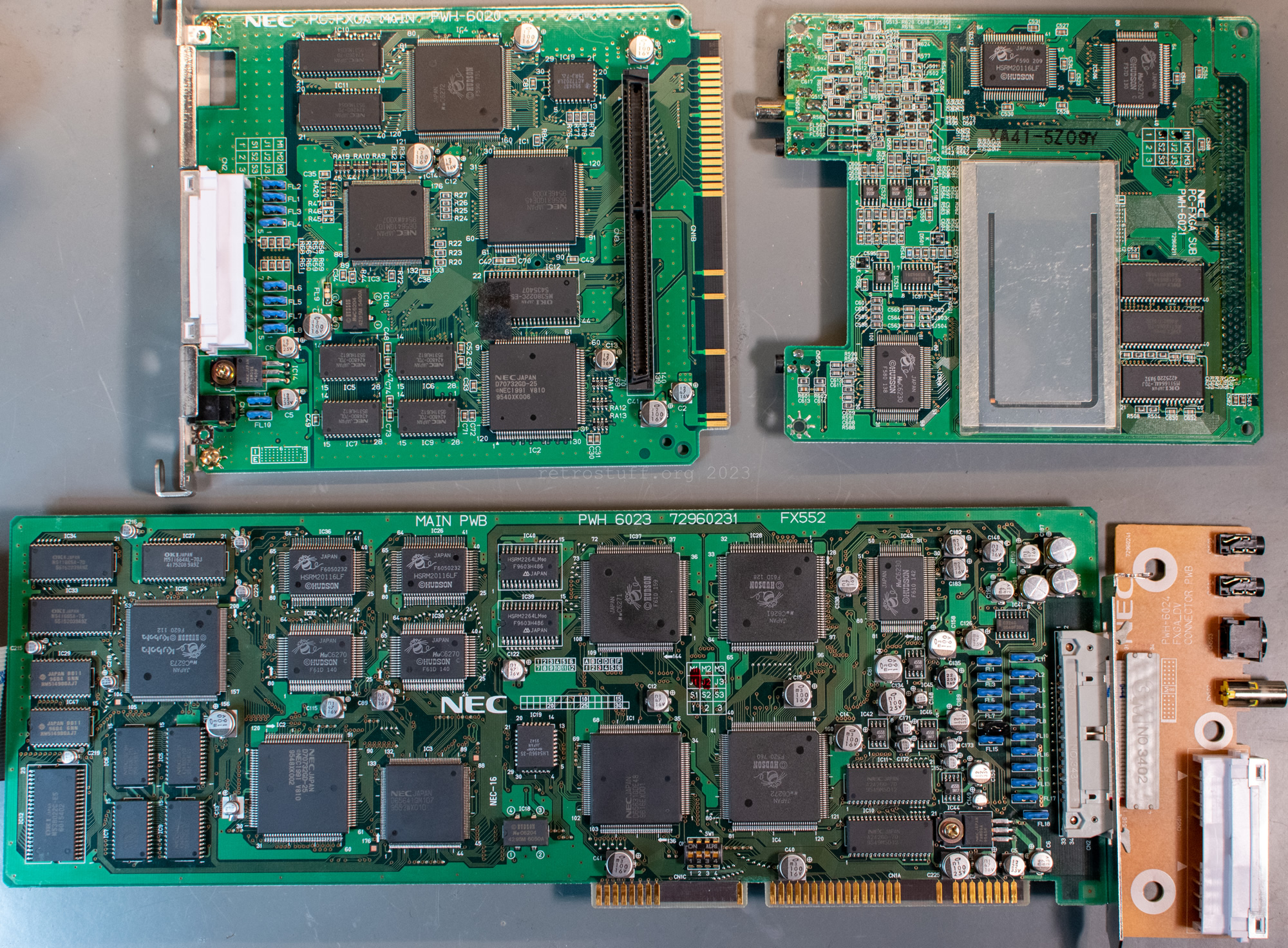
NEC PC-FXGA MAIN PWH-6020 72960201
The power supply and PAD connectors are located on the main PCB.
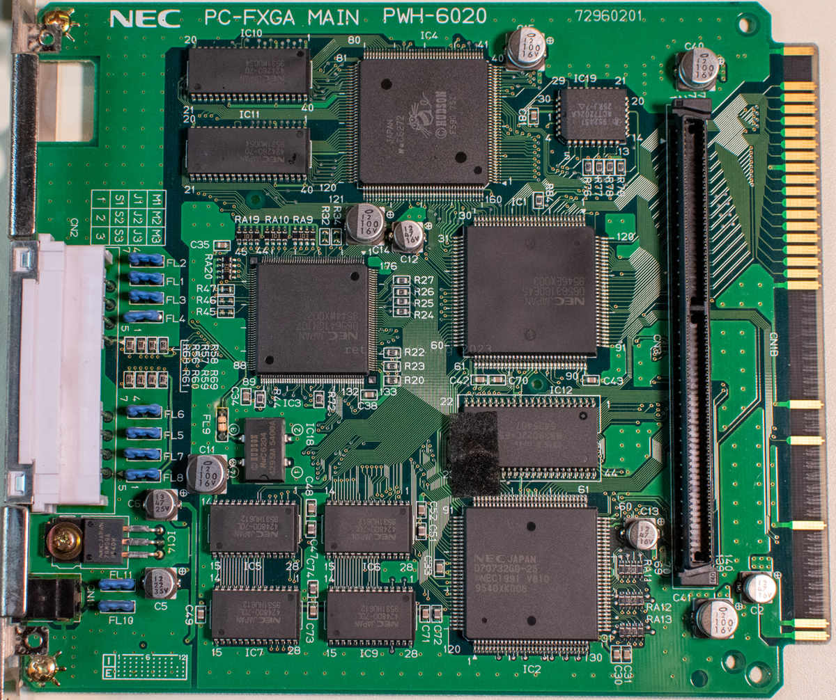
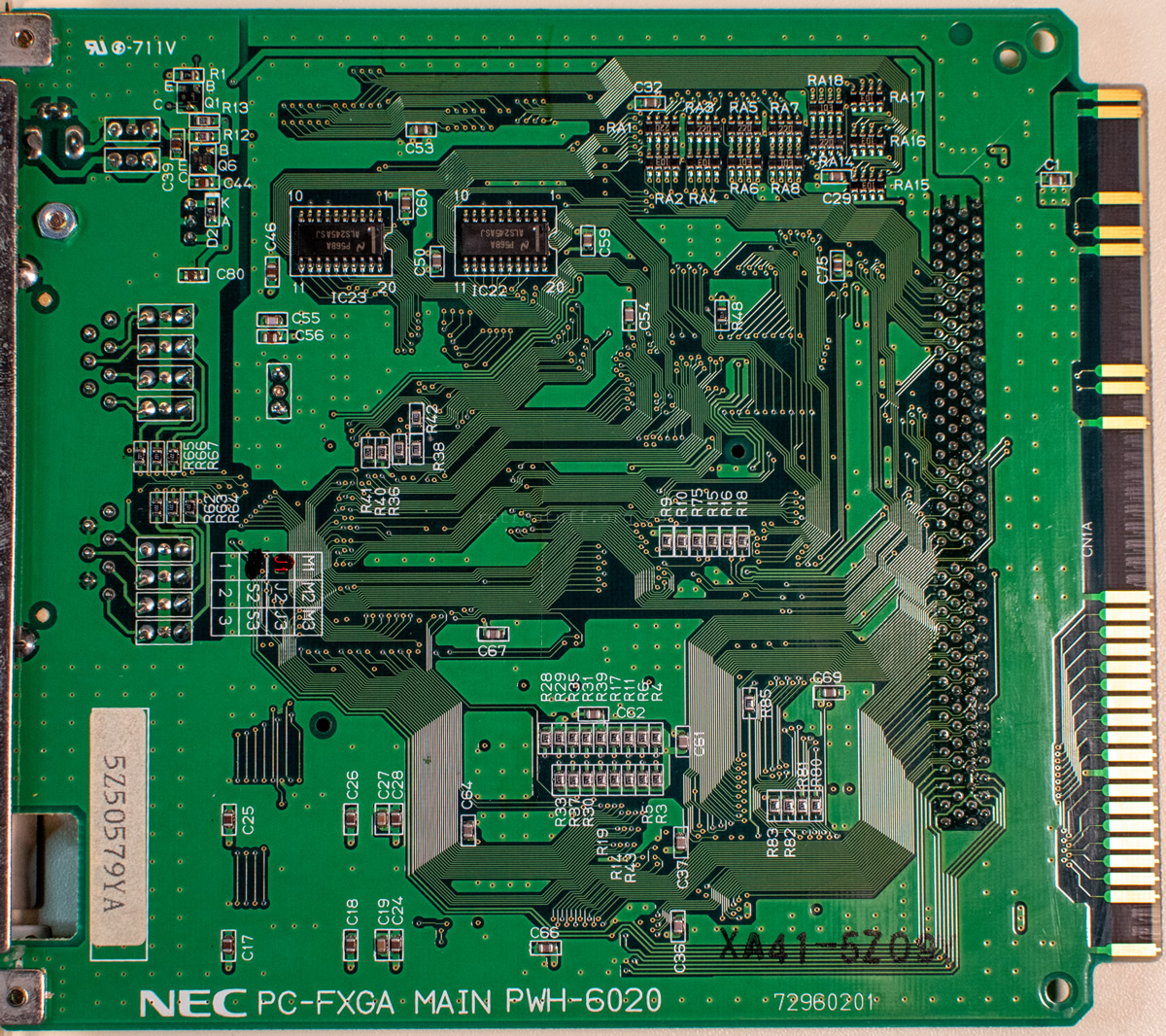
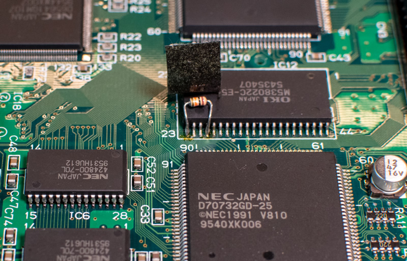
The OKI M538022C mask ROM on the main PCB has a bodge resistor between Vcc and D5.
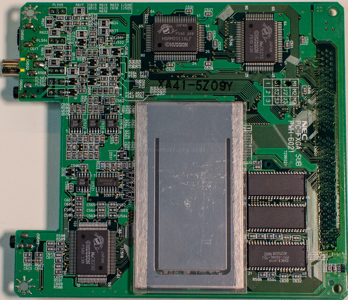
NEC PC-FXGA SUB PWH-6021 72960211
On the sub PCB, there is a shield/heat dissipating cover over HuC6271 (MotionJPEG processing chip) and HuC6273 (3D chip). I did not remove it and just deduced what is underneath based on the number of pins and the remaining visible chips.
The video and audio connectors are located on this PCB.
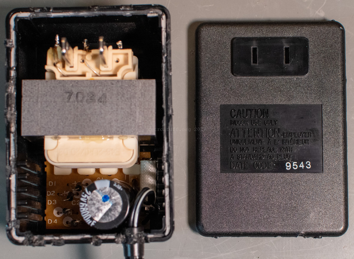
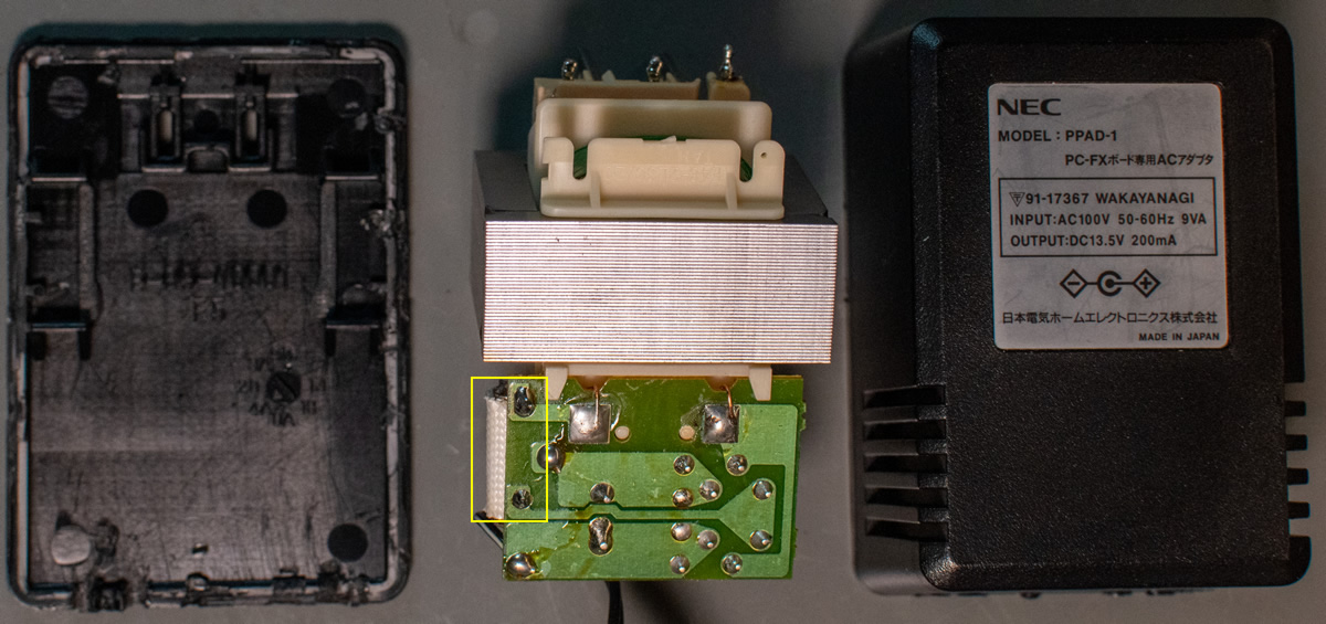
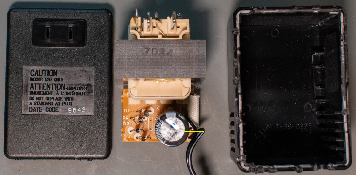
Power supply PPAD-1
PC-FXGA(98) (and also FX-98IF) require an external power supply (13,5 V DC / 200 mA) for operation (EIAJ-04 connector). I found out years ago that the fuse had blown and quickly discovered that the power supply was glued together and could not be opened without leaving damage. Unfortunately I didn’t take any photos at the time so I’m not sure if it was a 5 x 15 or 5 x 20mm miniature glass fuse. I replaced it with a 5 x 20 mm fuse, 1,6 A slow-blow / 250 V (T1.6L250V).
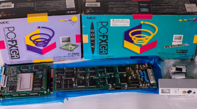
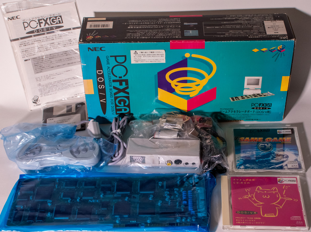
PC-FXGA DOS/V / PC-FXGA(DS)
The PC-FXGA DOS/V package is just as impressive as its PC-98 counterpart:
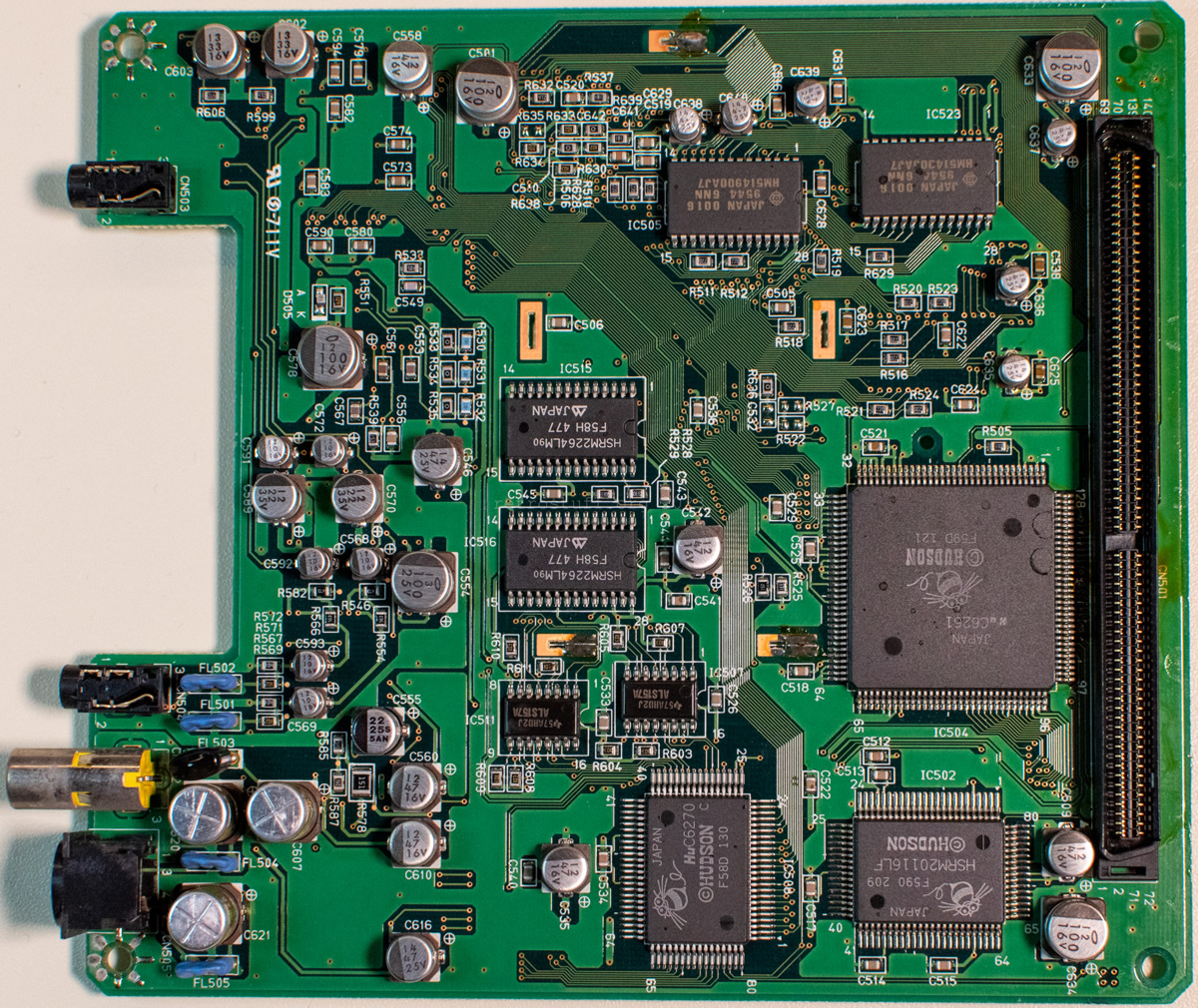
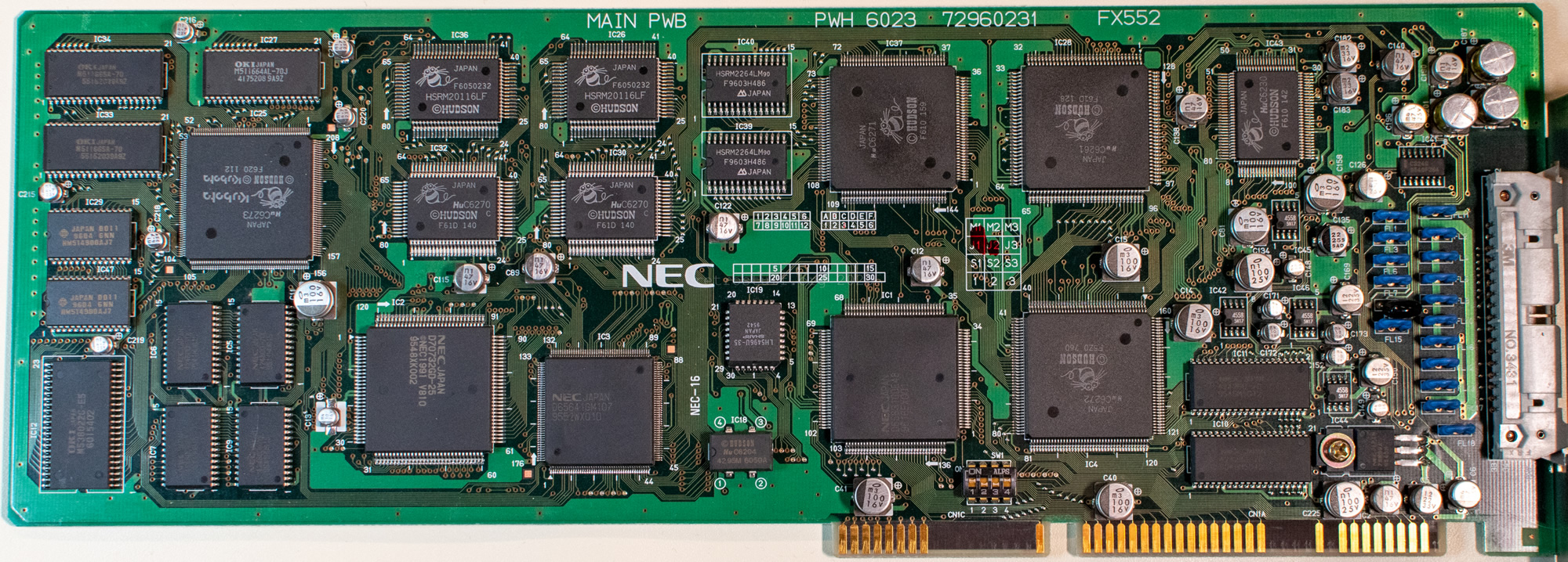
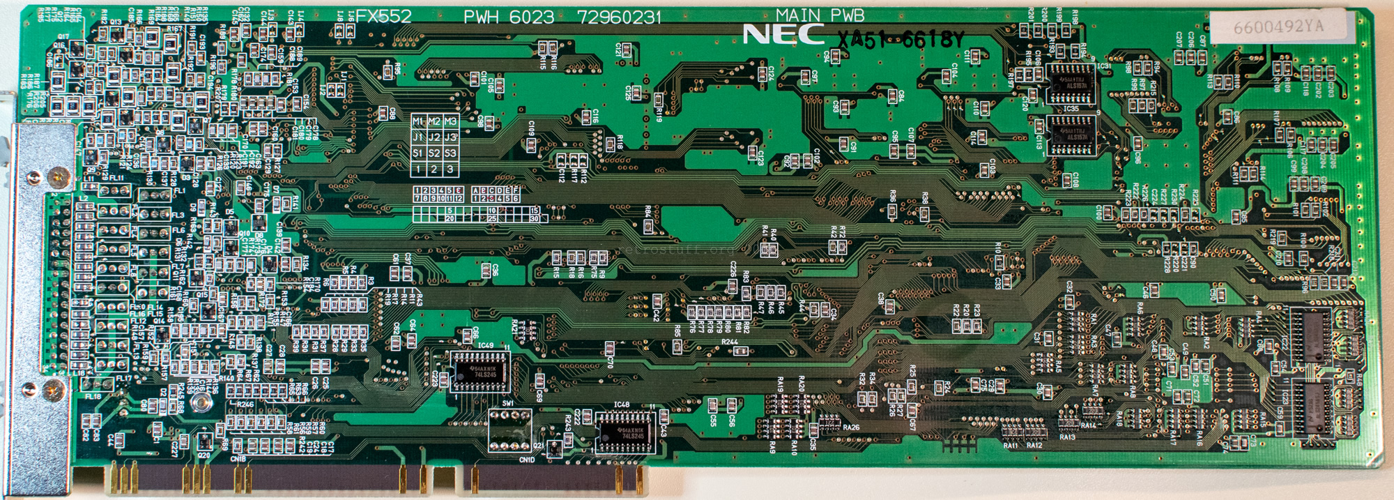
MAIN PWB PWH 6023 72960231 FX552
This is a full-size 16-bit ISA card that utilises all the available space (and even more, hence the breakout box):
Before we get to the main reason for this article, you can see all the PC-FXGA boards side by side in one photo:
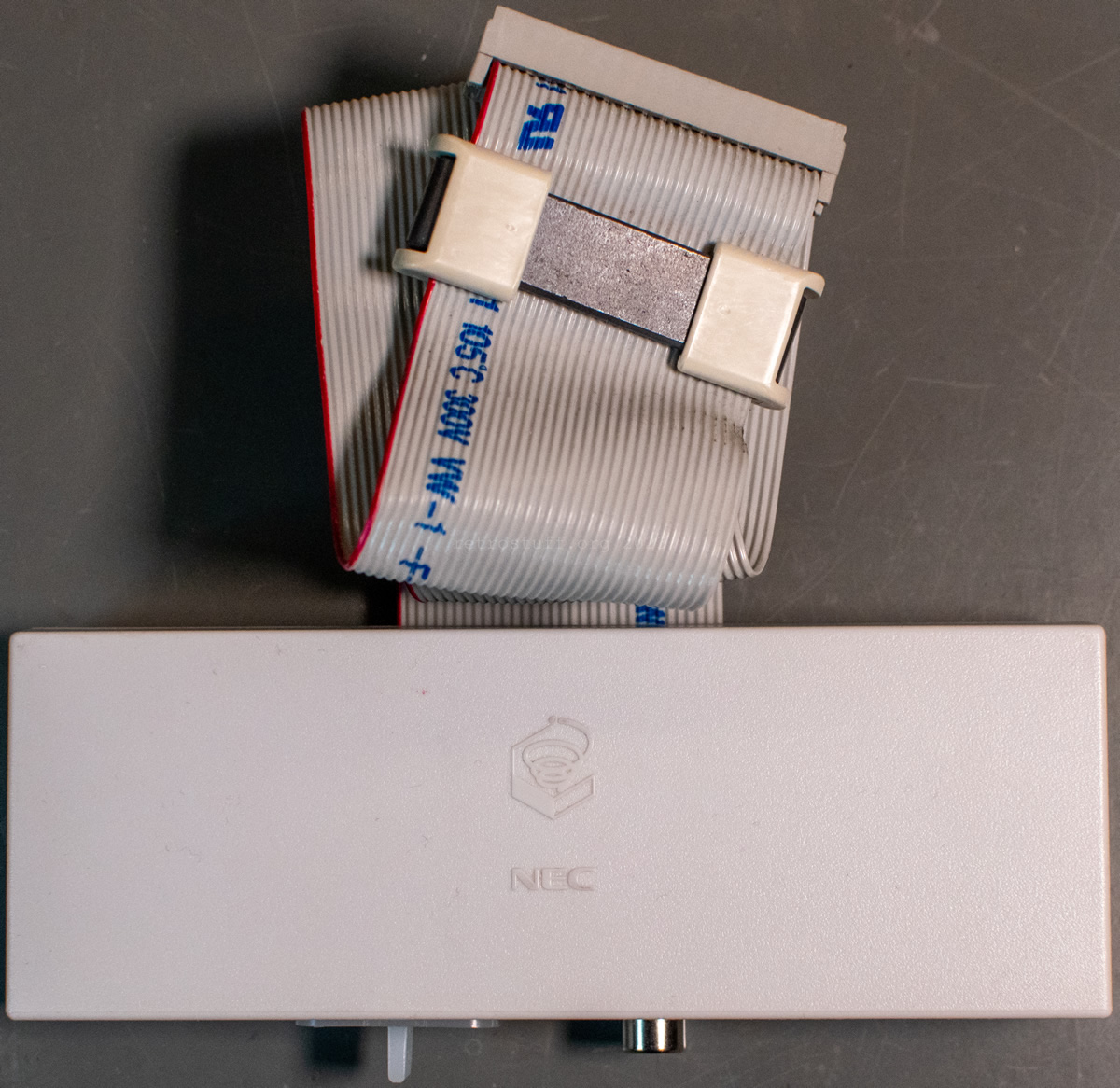
Breakout box
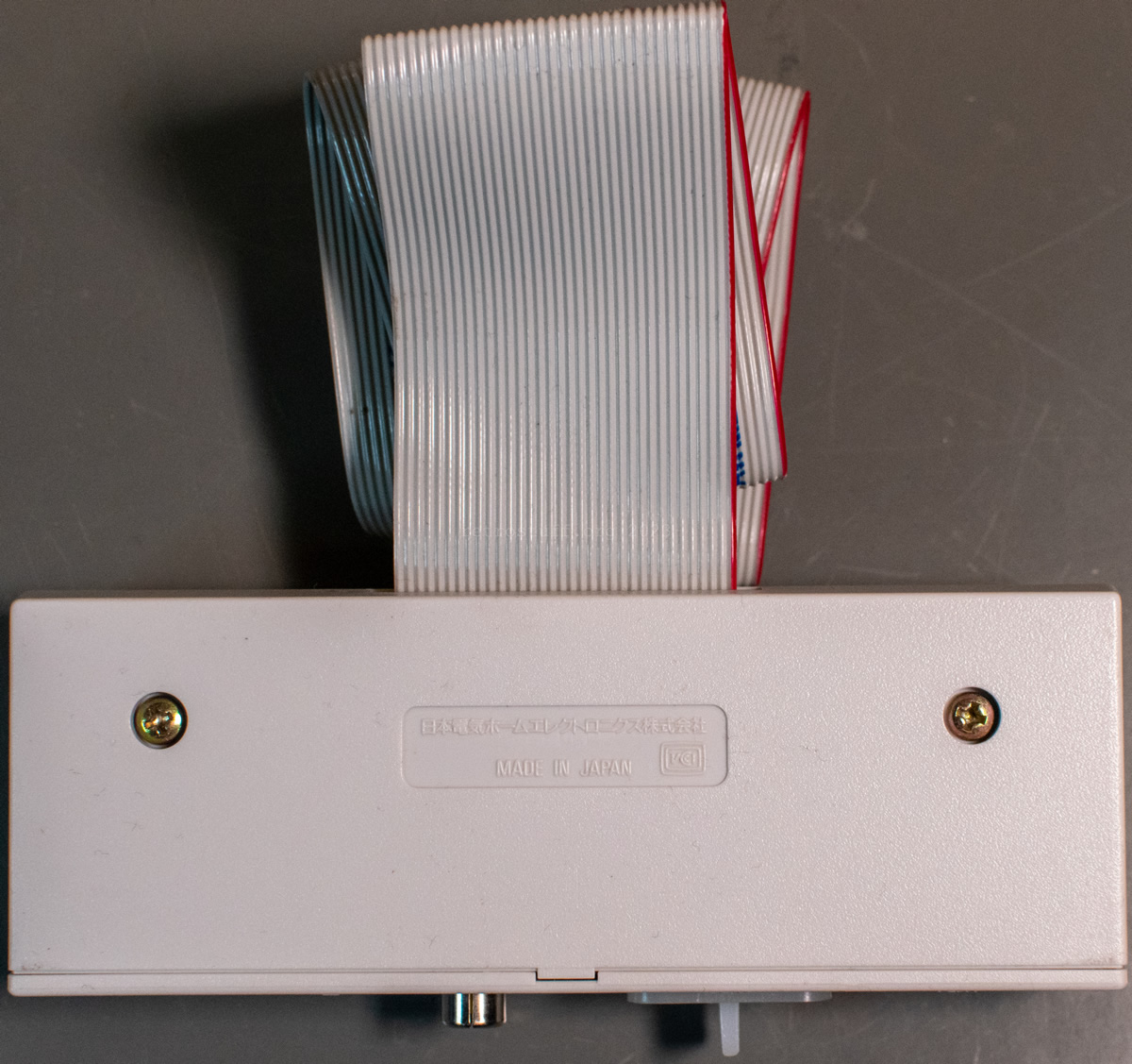
Due to the limited space on an ISA slot bracket, NEC has opted to house all inputs and outputs in a breakout box, which is connected via a 34-pin ribbon cable with IDC connector (i.e. virtually an FDD cable). Without this breakout box, the card is practically unusable.
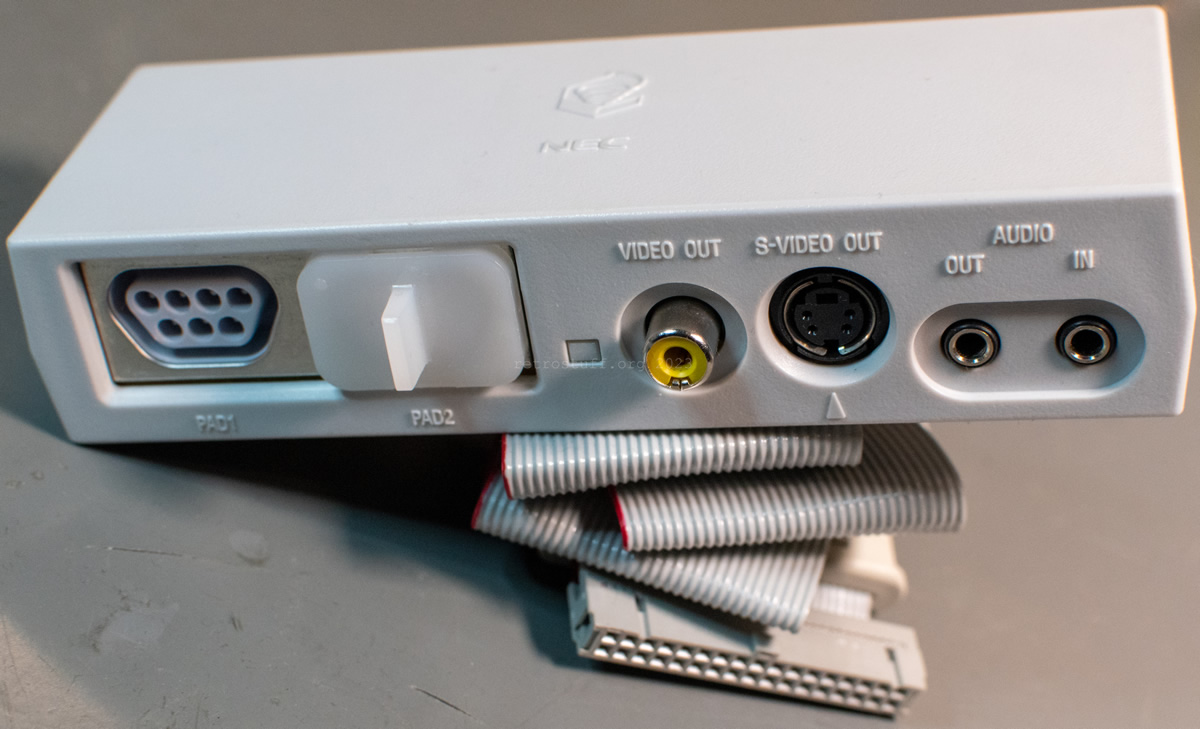
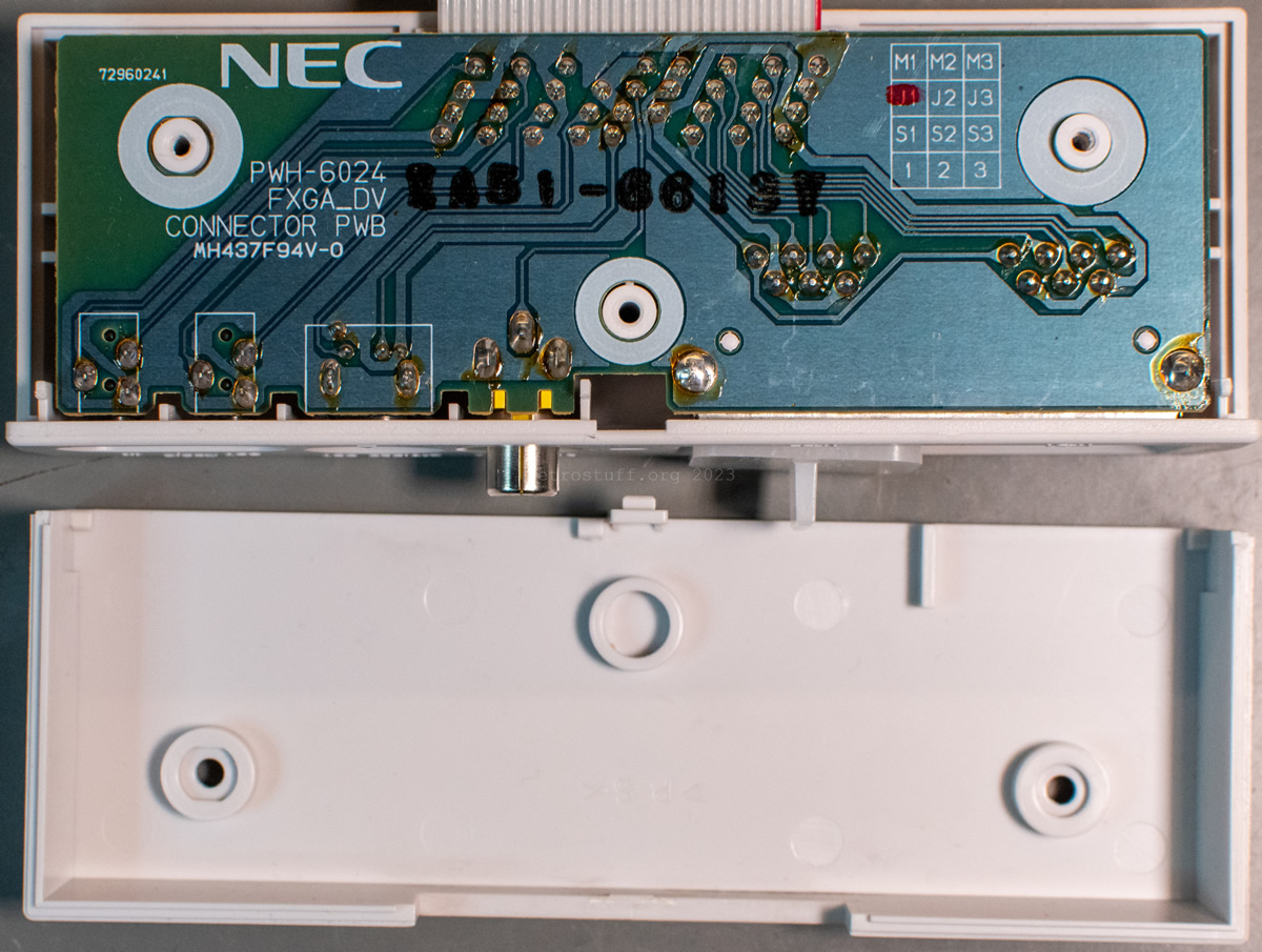
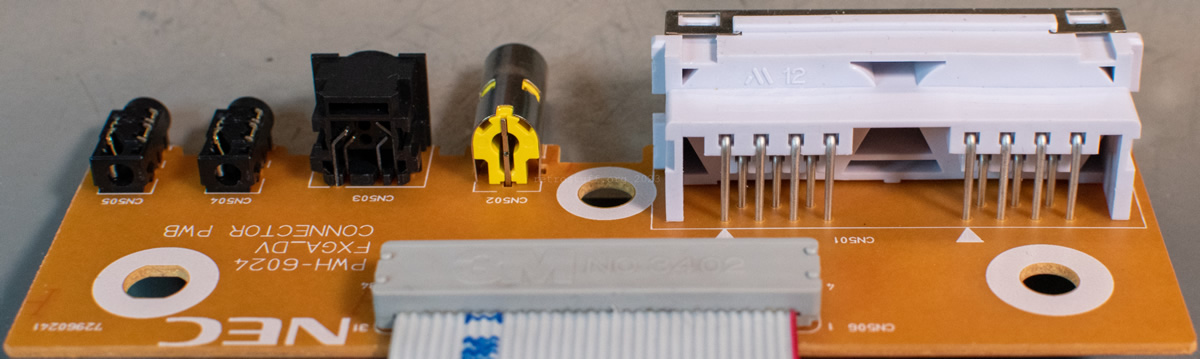
PWH-6024 FXGA_DV CONNECTOR PWB 72960241
Inside, there are only six connectors on the PCB. They are all off the shelf, with the exception of the PAD connectors (CN501) – these still need to be found out or rebuilt with more common components.
- CN501 – proprietary PC-FX controller sockets
- CN502 – RCA socket
- CN503 – 4-pin mini-DIN socket
- CN504, CN505 – 3 mm TRS phone sockets
- CN506 – 3M 3402 PCB Connector
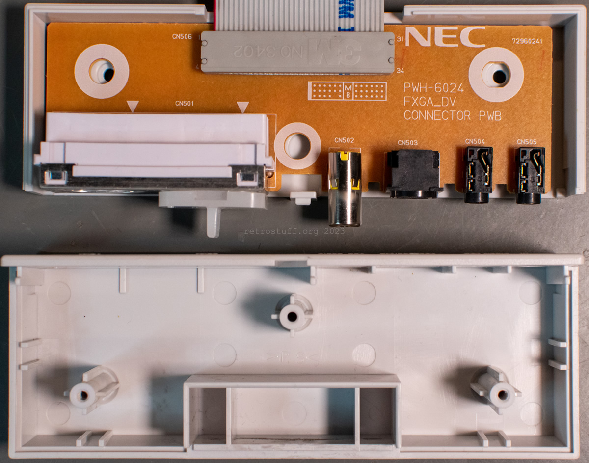
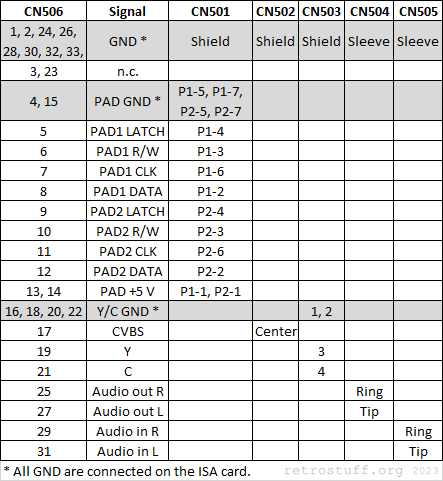
Here are pin assignments and wiring for all connectors so that the breakout box can possibly be rebuilt one day. The PAD signal designations correspond to these controller pinouts.
If this project ever develops into something concrete (I just had a few ideas for a quick and dirty rebuild), I’ll update this article accordingly.
More PC-FX(GA) resources
- PC-FX MoeMoe (Japanese)
- APC-Project (Japanese) and Daifukkat.su (English translation)
- pcfx-devel/PC-FX_Info: Technical Information about the PC-FX
- PC-FXGA – WIP
- What did we do to deserve the PC-FX? (and the PC-FX GA)
One thought on “NEC PC-FXGA, PC-FXGA DOS/V, and its Breakout Box”