
This article is about implementing the following Sega Saturn modifications: Region-free BIOS, FRAM, and switchless 50/60 Hz.
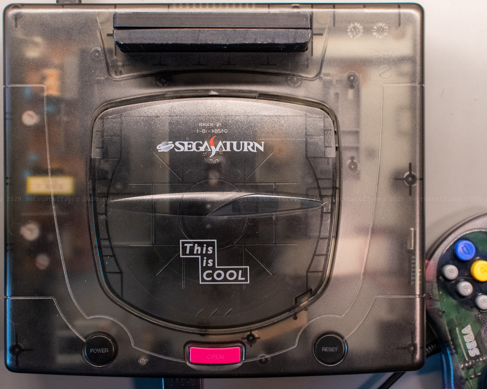
But first, we’ll need to go back in time a decade or so. Back then, I was modifying my “This is COOL” skeleton SegaSaturn (HST-0021/HST-3220) like crazy, stuffing everything inside that I could find:
- V2 modchip
- The ultimate Sega Saturn Switchless Mod
- A/V out mod for EU SCART cables
- EU Type-C PSU to supply 9V for the A/V out mod
- Region-free BIOS chip
The region-free BIOS, however, gave me plenty of trouble and I had to put the original BIOS back in. The Saturn has worked fine for the past nine years, by the way.
This year, I wanted to finally finish what I had started back then. I also wanted to replace the battery-backed SRAM with an FRAM and simplify the 50/60 Hz switching.
Starting over
For a clean start, I did a physical inventory and changed almost everything back to factory state.
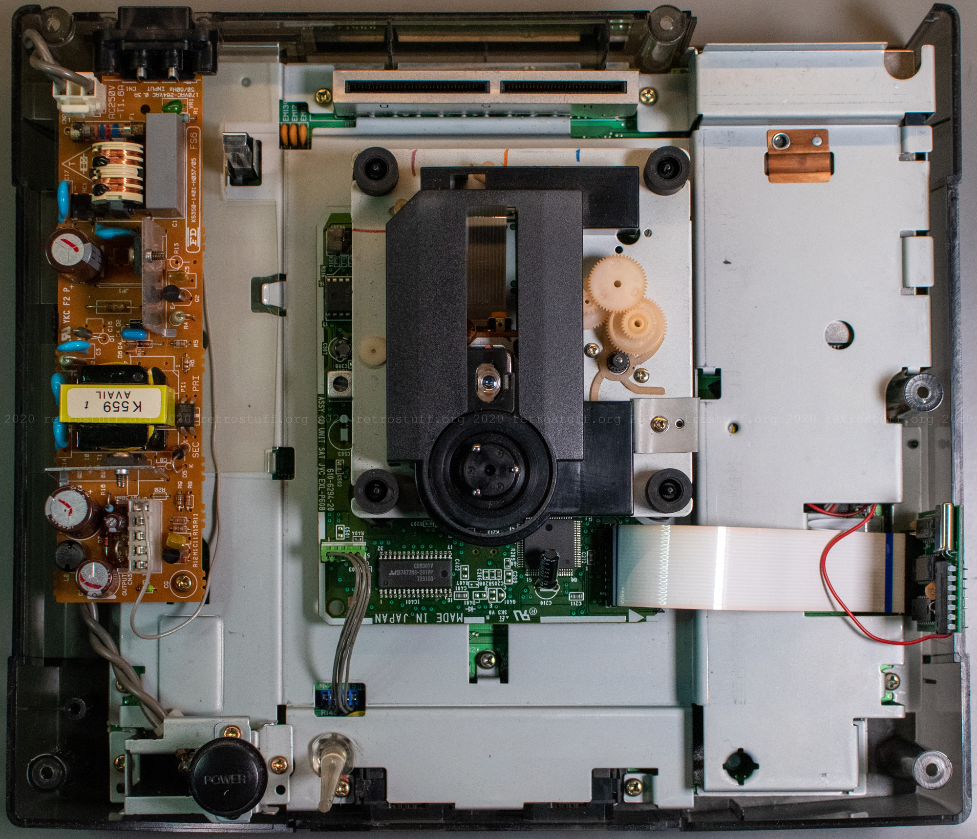
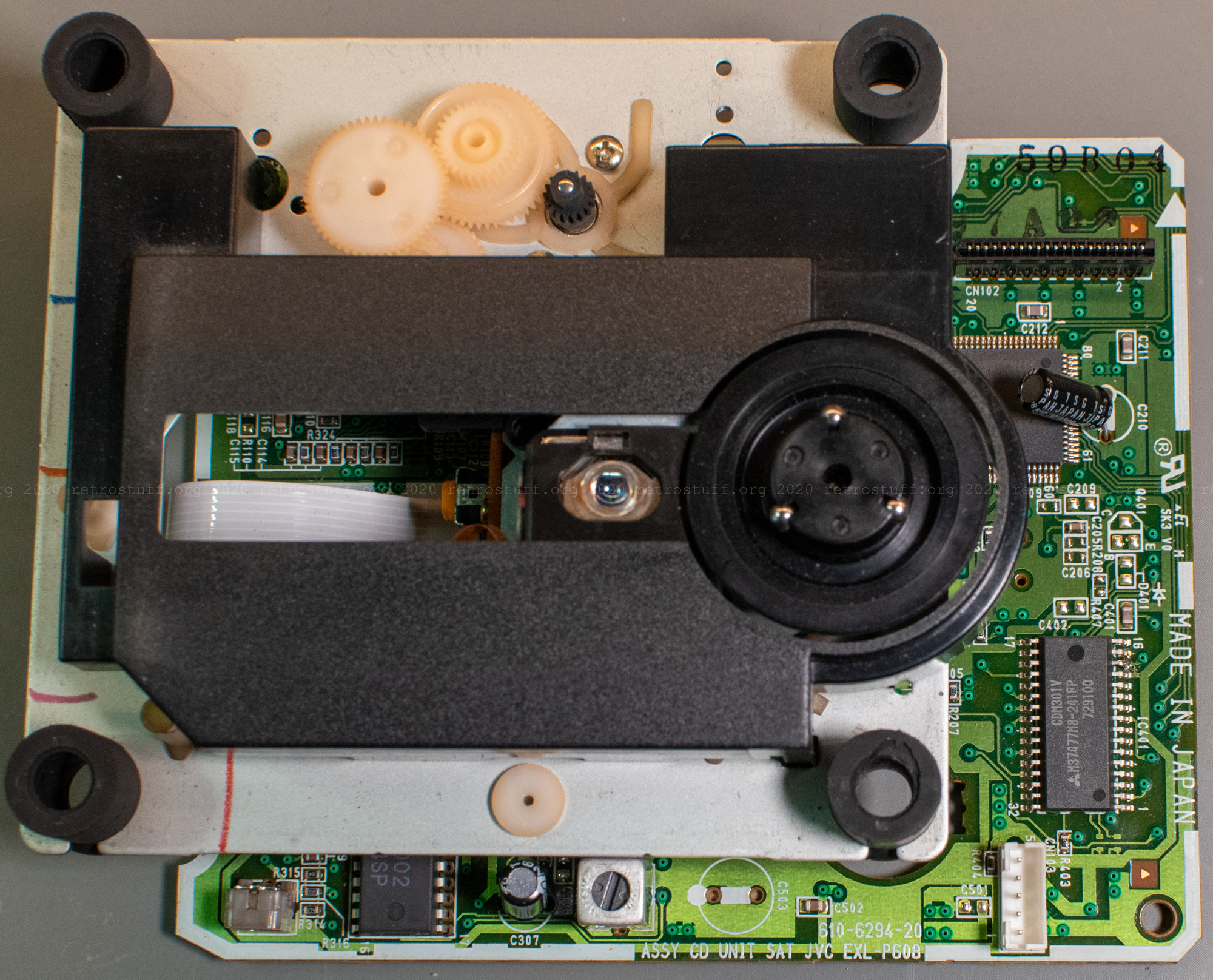
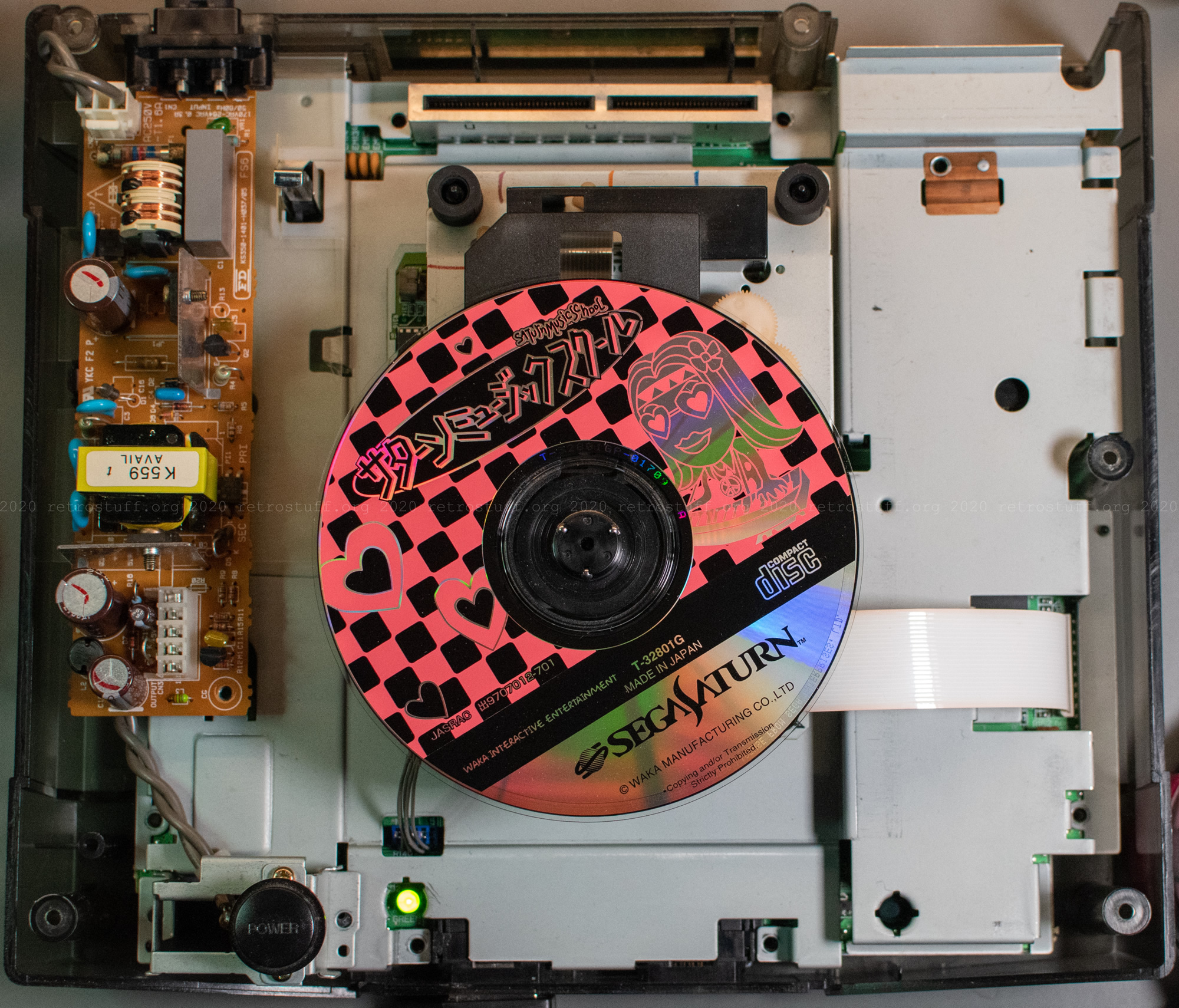
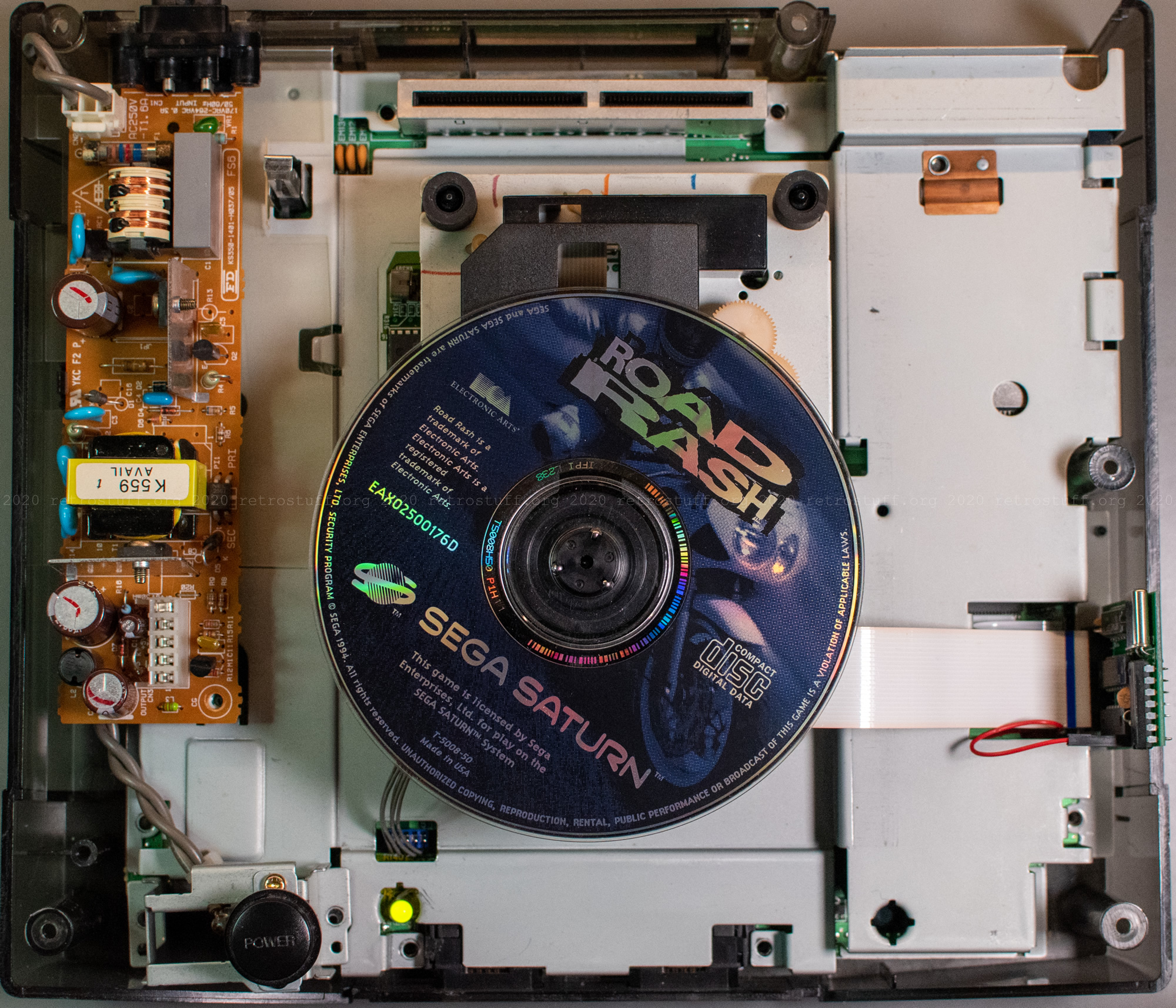
There’s nothing too suspicious under the lid: A Type C EU power supply with the 9 V wire to the A/V port on the left and the modchip with the +5 V wire that goes to some place inside on the right. Also on the pictures: The JVC CD-ROM drive with 21-pin connector.
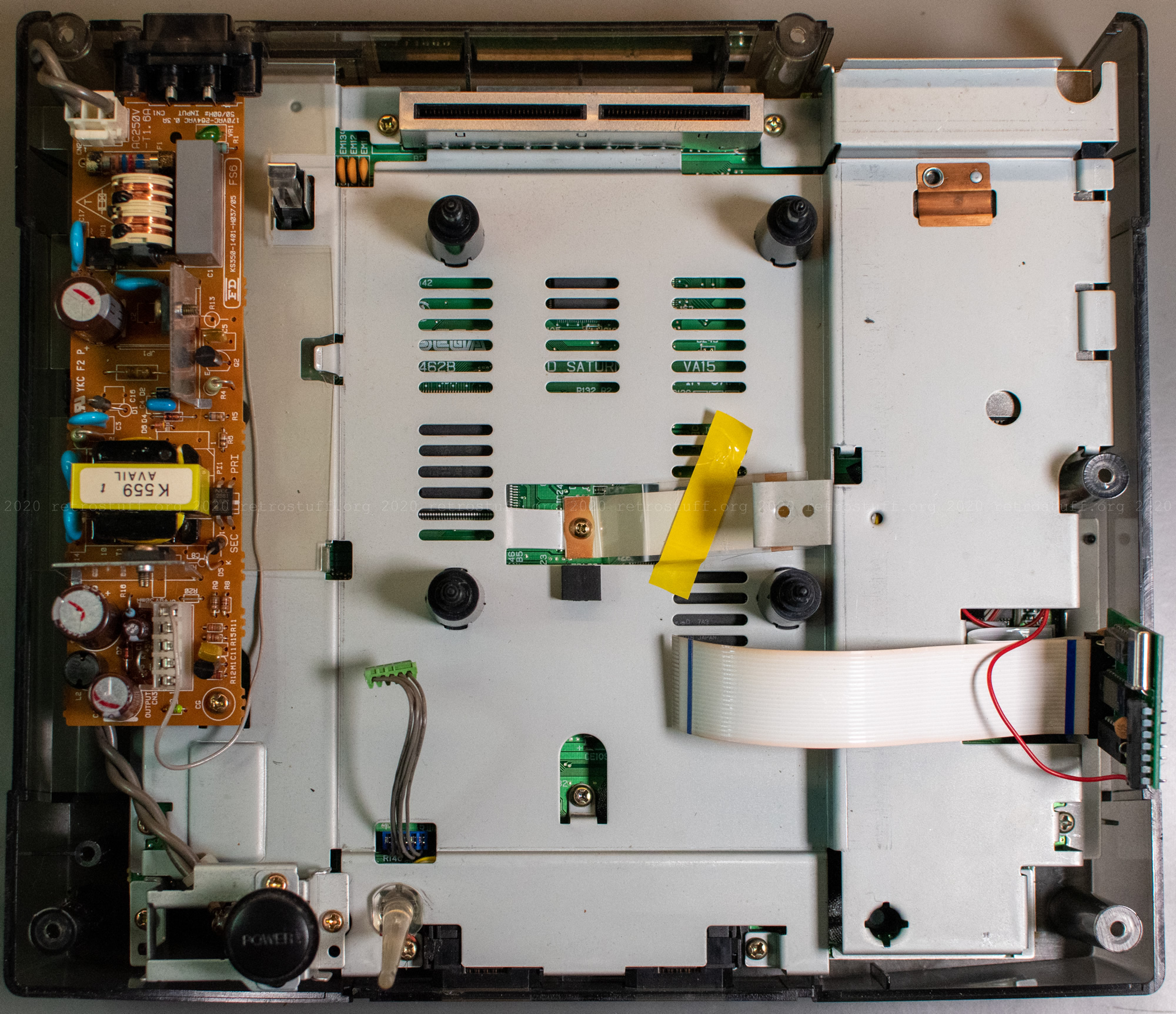
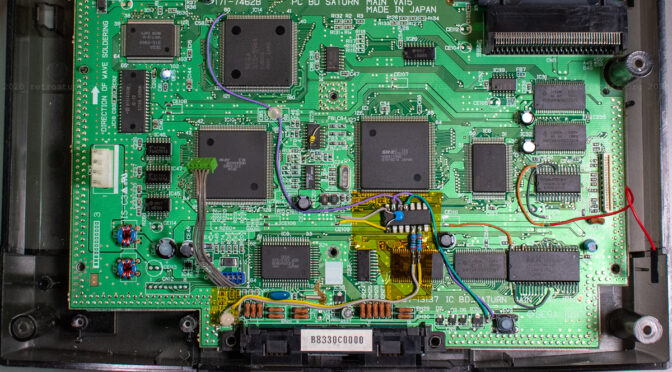
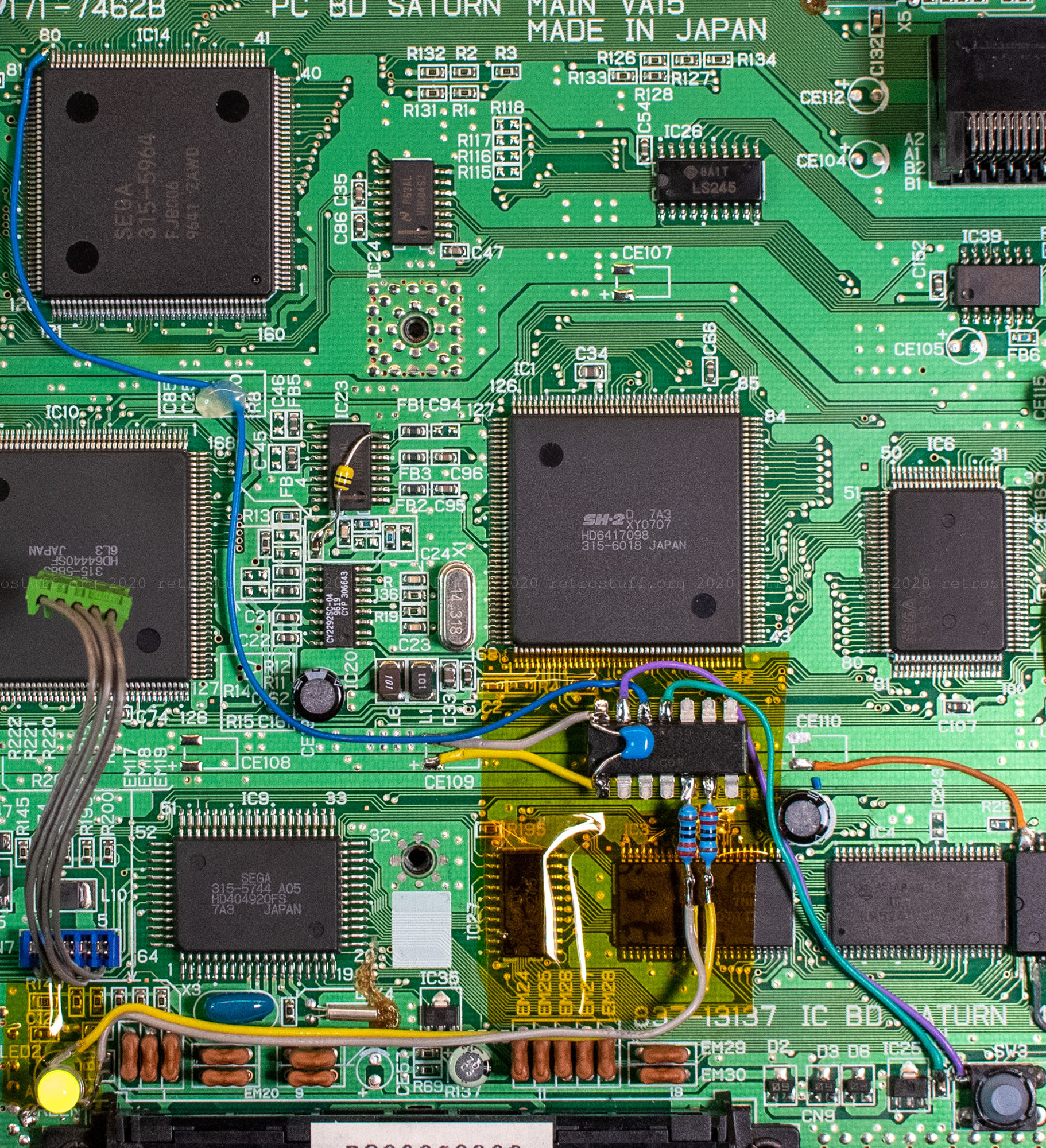
It’s getting nasty underneath the metal case. Here are some impressions of the VA15 mainboard with the various modifications:

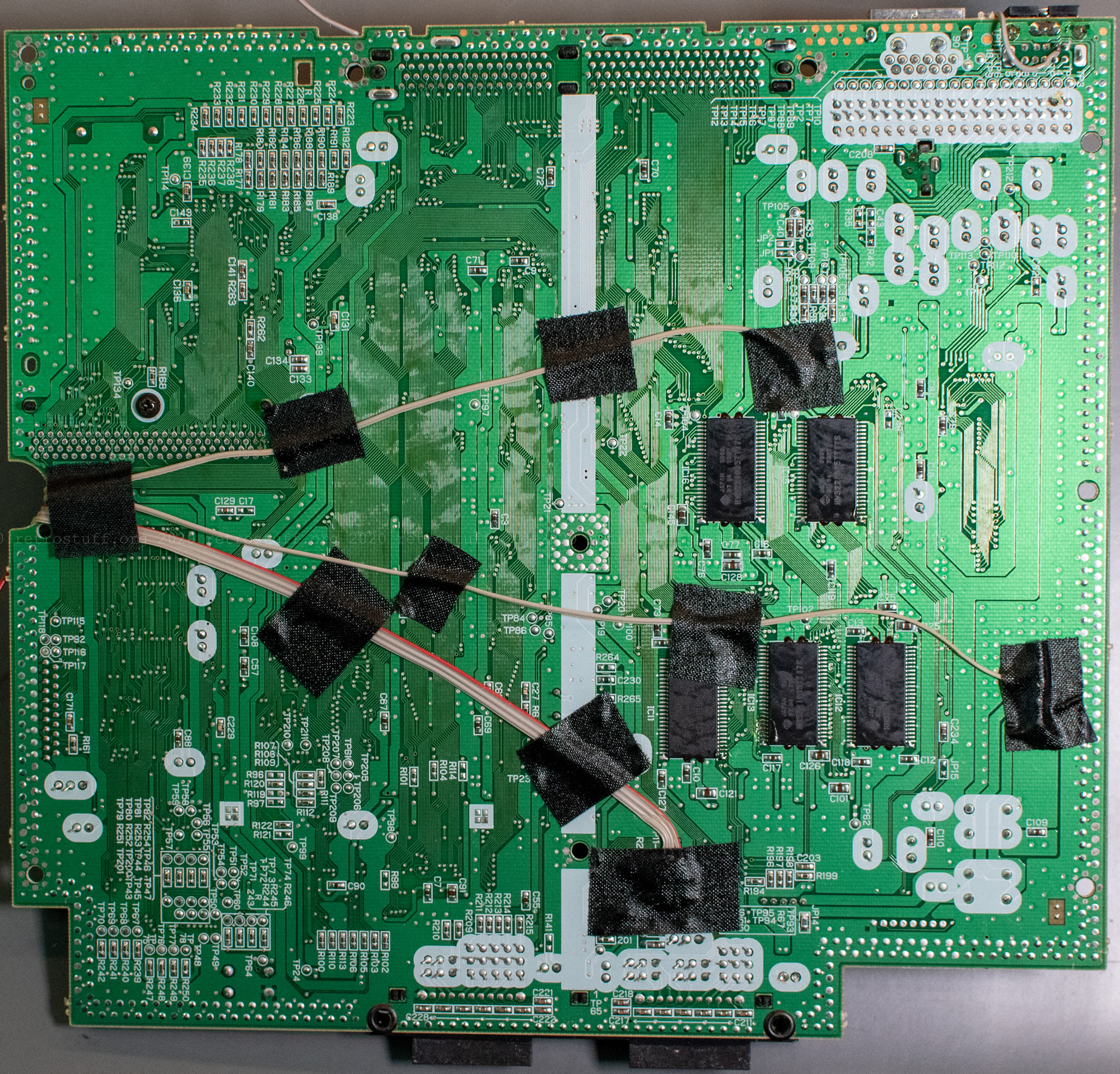

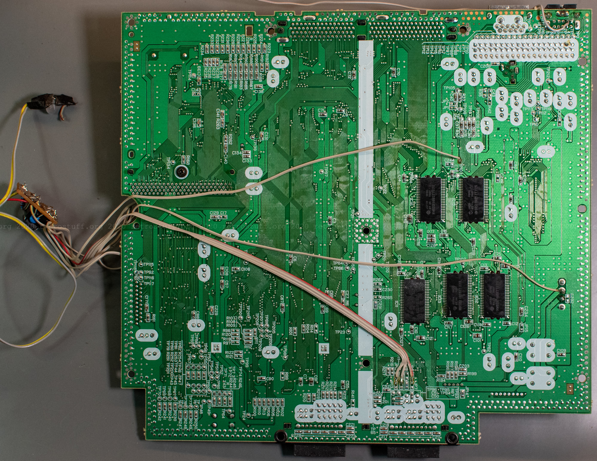
(I really like this kind of insulation tape because it sticks where it is supposed to stick. However, the ingredients dissolve over the years; the tape has dried out and the goo is stuck to all components and cables. Let’s see how the fake Kapton tape that I have since started using instead looks and feels in 10 years.)
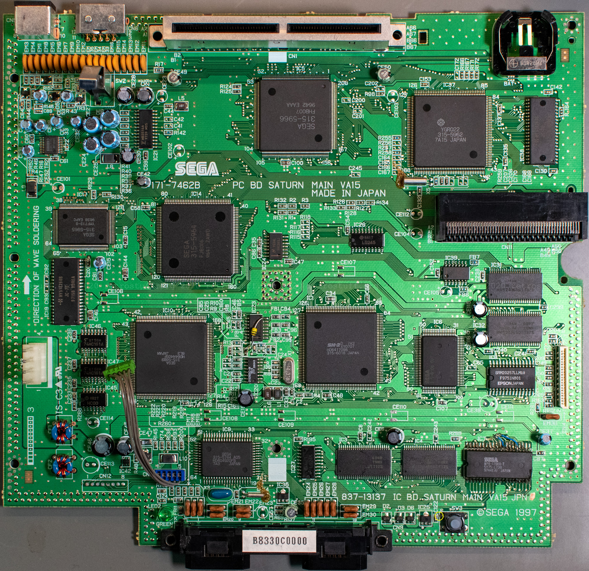
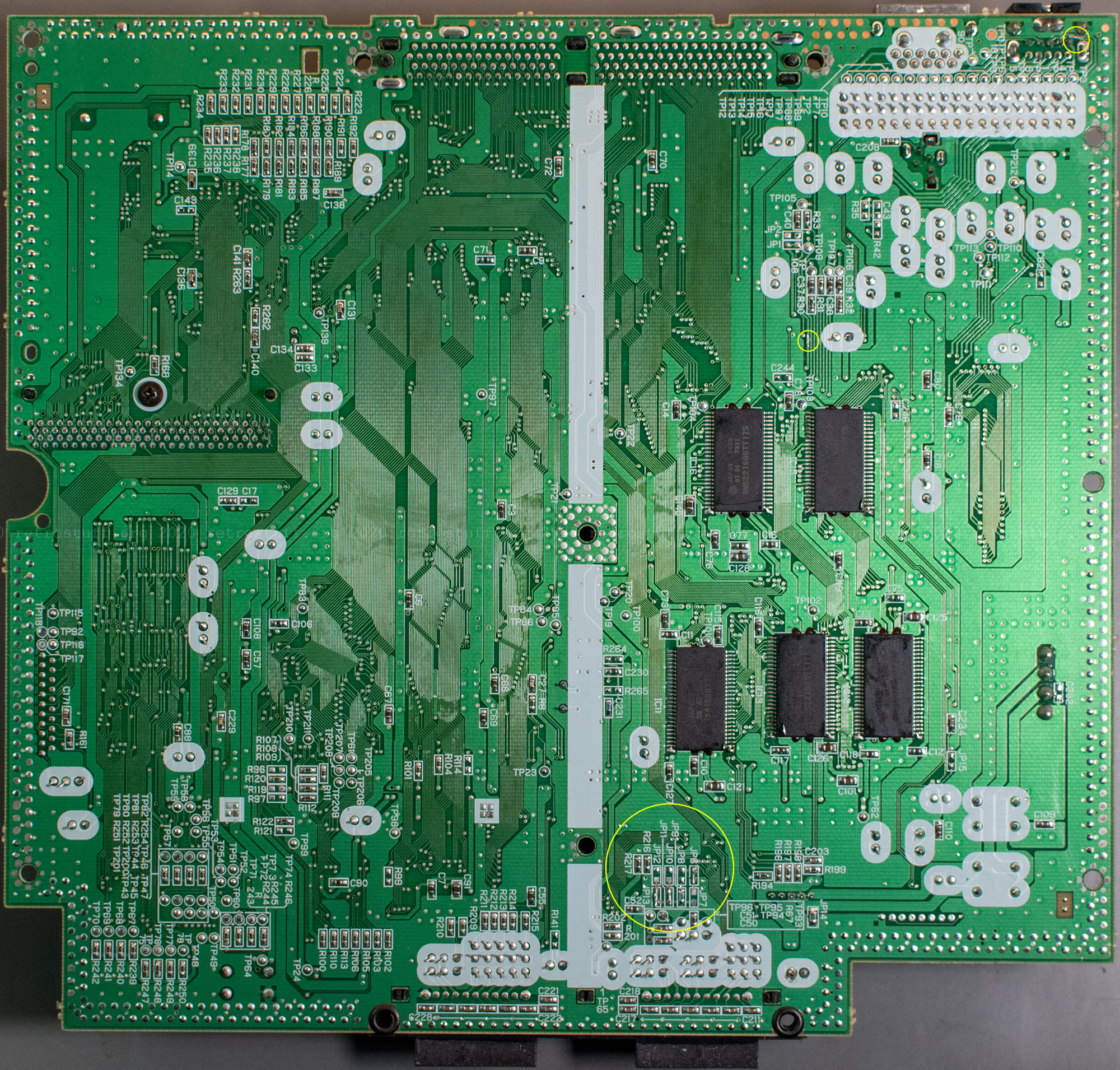
After removing all modifications and cleaning up the goo, the mainboard looks like this. All jumpers and cut traces (yellow circles) were changed back to the factory configuration (except the one next to the reset button). I even soldered the original green LED back in.
One last, successful test with an original Japanese game before I started with the new modifications.
Region-free BIOS
The region-free BIOS has the region lockout removed and allows you to play (original) games from all regions. There is an excellent tutorial by mmmonkey that also takes care of the video mode.
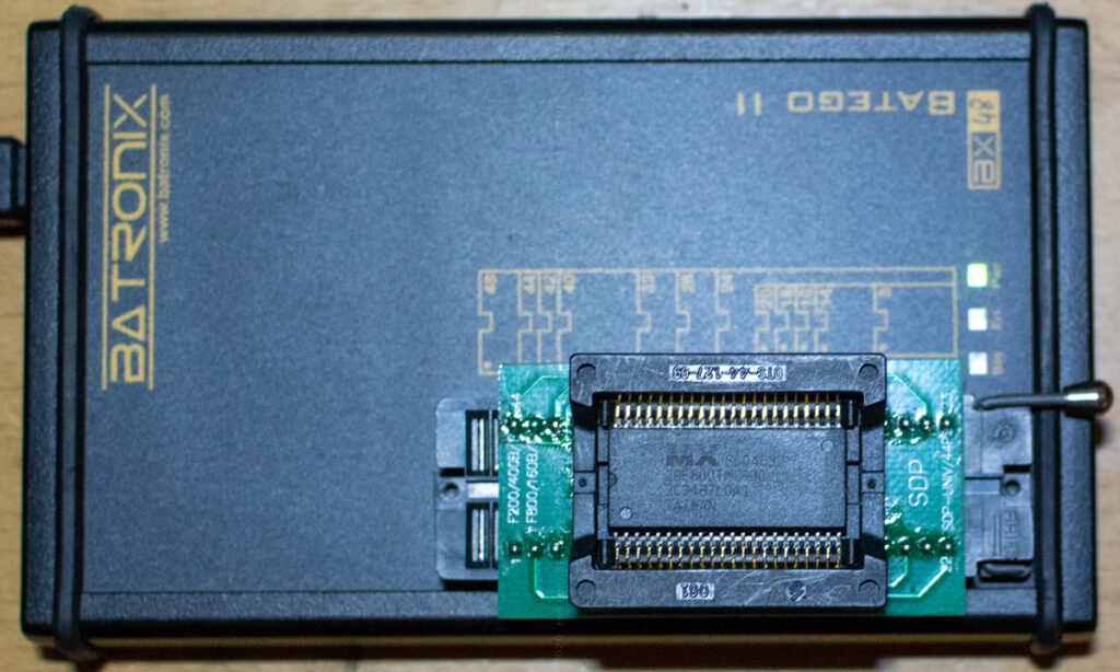
But, before attempting to swap the BIOS chips again, I had a thorough look at the content of the remaining flash memory chips that I had ordered years ago. It was assumed that it failed because the content wasn’t byte-swapped. My EPROM programmer did not have a driver for this type (Macronix MX29F800TMC-90), so I chose the driver for the newer, pin-compatible variant MX29F800CTMI-90.
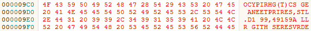
I was able to successfully extract the content and searched for the copyright string. If it was really byte-swapped, it should say OCYPIRHG.
Since all was fine, I was ready to proceed, but I still took one last precautionary measure: Usually, the region-free BIOS file is duplicated, byte-swapped and then written onto the chip. Instead of duplicating it, I combined the region-free and the original JP 1.01 BIOS file (copy /B Sega Saturn BIOS v1.01 (multinorm).bin + sega_101.bin newbios.bin). If for whatever reason the region-free BIOS didn’t work, I could still fall back to the original BIOS by connecting address line A18 (pin 2) to +5 V instead to GND.
(Hint: It is also possible to combine two different versions, e.g. EU/US 1.01a with JP 1.01 or the more exotic GameNavi HiSaturn 1.03 BIOS to switch between different startup animations.)
Replacing the BIOS chip
This time, I carefully removed the old BIOS chip with hot air and plenty of flux and examined the damage. Five solder pads were damaged during the rescue operation nine years ago, so I removed what was left of them.
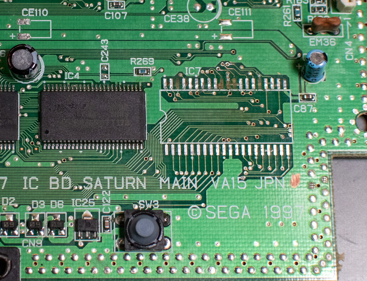
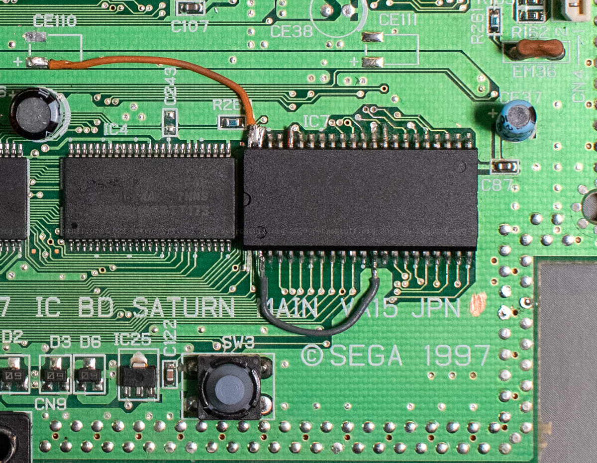
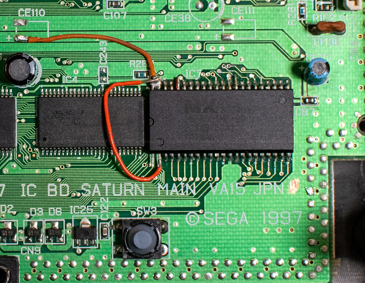
For the missing pad on the left, I soldered a small piece of Kynar wire to the via hole underneath the chip and to the lifted pin 40 of the new flash memory chip. The four other pads weren’t a big problem because the new chip has a larger footprint. I was able to solder the legs right to the adjacent traces and only one of them needed a tiny piece of wire as extension.
Testing region-free (pin 2 to GND) and unaltered (pin 2 to +5 V) BIOS versions:
There were no issues this time; my Saturn was able to boot with both BIOS versions right away.
FRAM modification
The Sega Saturn has a power-hungry RTC. When the battery is empty, not only are the date/time and language settings lost, but also all game save files. To prevent this, I replaced the battery-backed SRAM with non-volatile FRAM. There are two articles on RetroRGB that explain in detail how it works and basic instructions on the Wolfsoft blog.
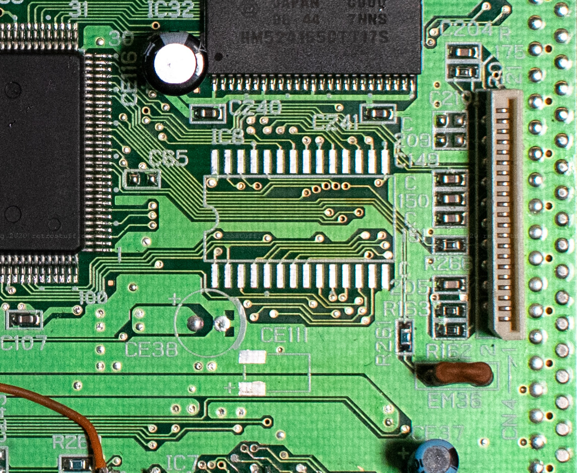
First, I located IC8 (SRM20257LLM10 in my Saturn) and removed it:
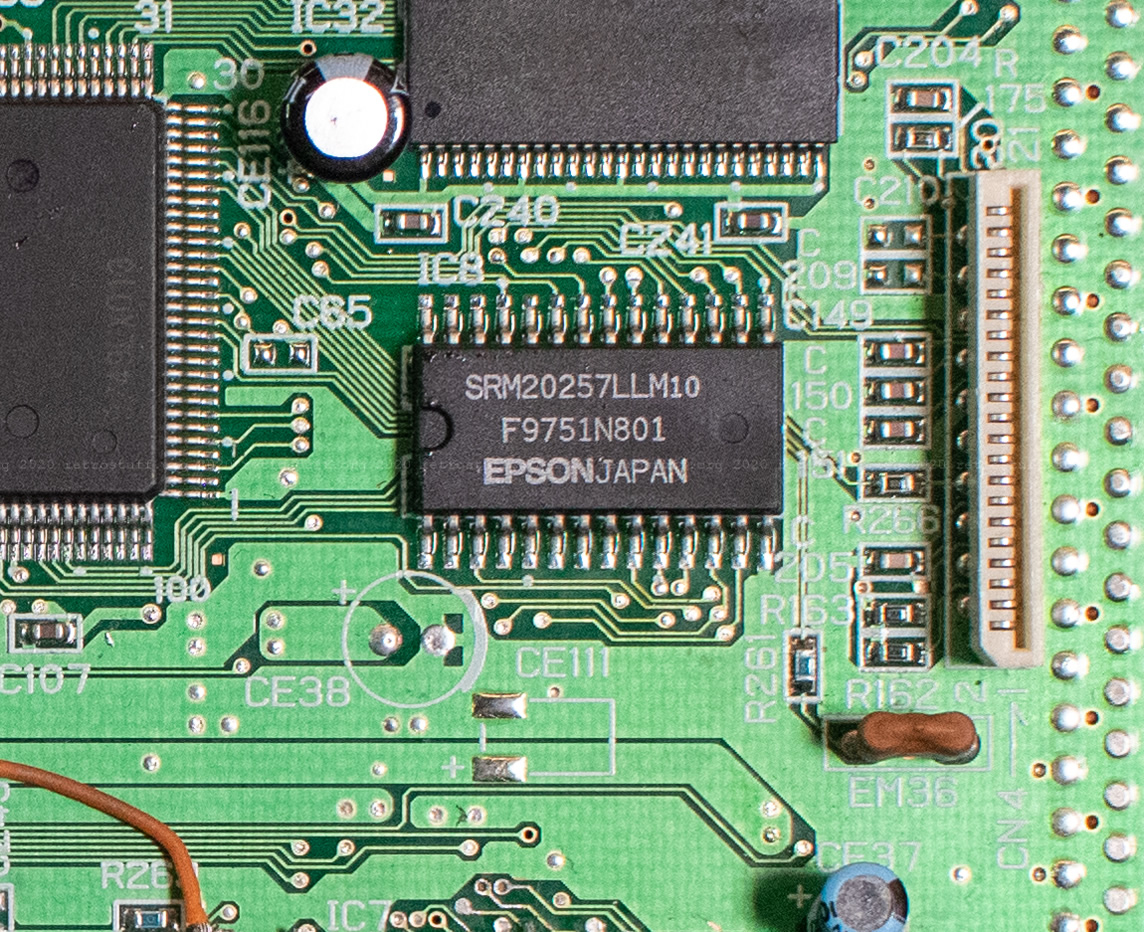
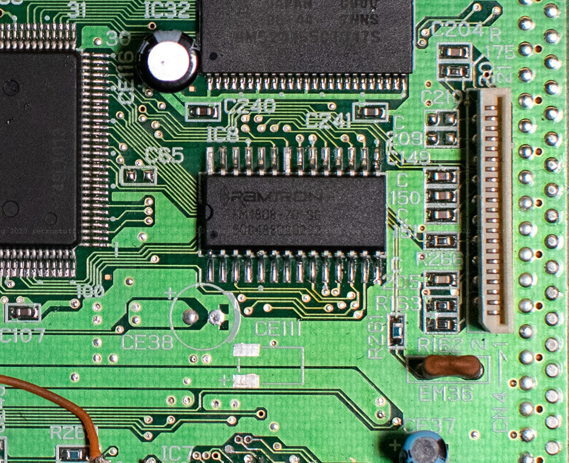
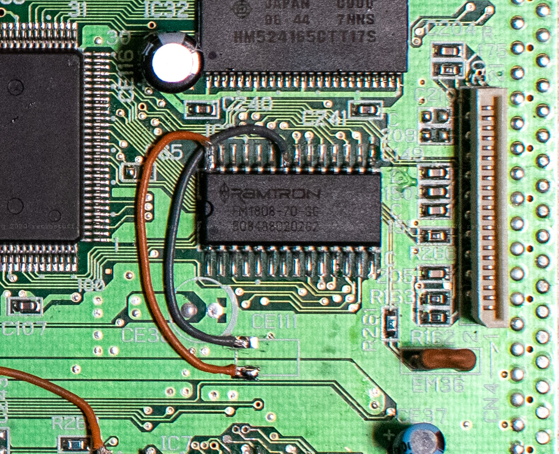
Then, I lifted pins 22 and 28 of a Ramtron FRAM (FM1808-70-SG) and soldered it back to where the SRAM chip was. And finally, I connected pin 22 to GND and pin 28 to +5 V. (Interestingly enough, it was also working when pin 28 was not connected at all.)
That’s it. The RTC will still suck the CR2032 battery dry and ask for date/time and language settings whenever that has happened, but the internal memory will be safe.
Switchless 50/60 Hz modification
With the region-free BIOS, most of the functions of Seb’s ultimate switchless mod are obsolete. The tutorial by mmmonkey provides a simplified version and program code of the aforementioned mod, reduced to switching the video mode only.
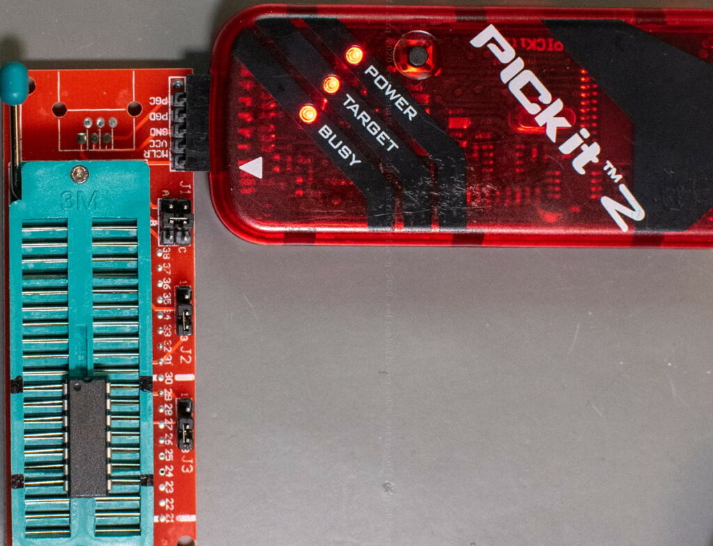
When I re-programmed the PIC16F630 microcontroller, I lost the internal calibration data (OSCCAL). This is something that can always happen, no matter how much attention you pay and how fancy your programmer is. The chip becomes practically useless and I had to throw away many PICs over the years; until I bought a PICkit 2 (clone) which can auto-generate the OSCCAL value via software. It helped me again this time, and I was able to successfully write the new program code.
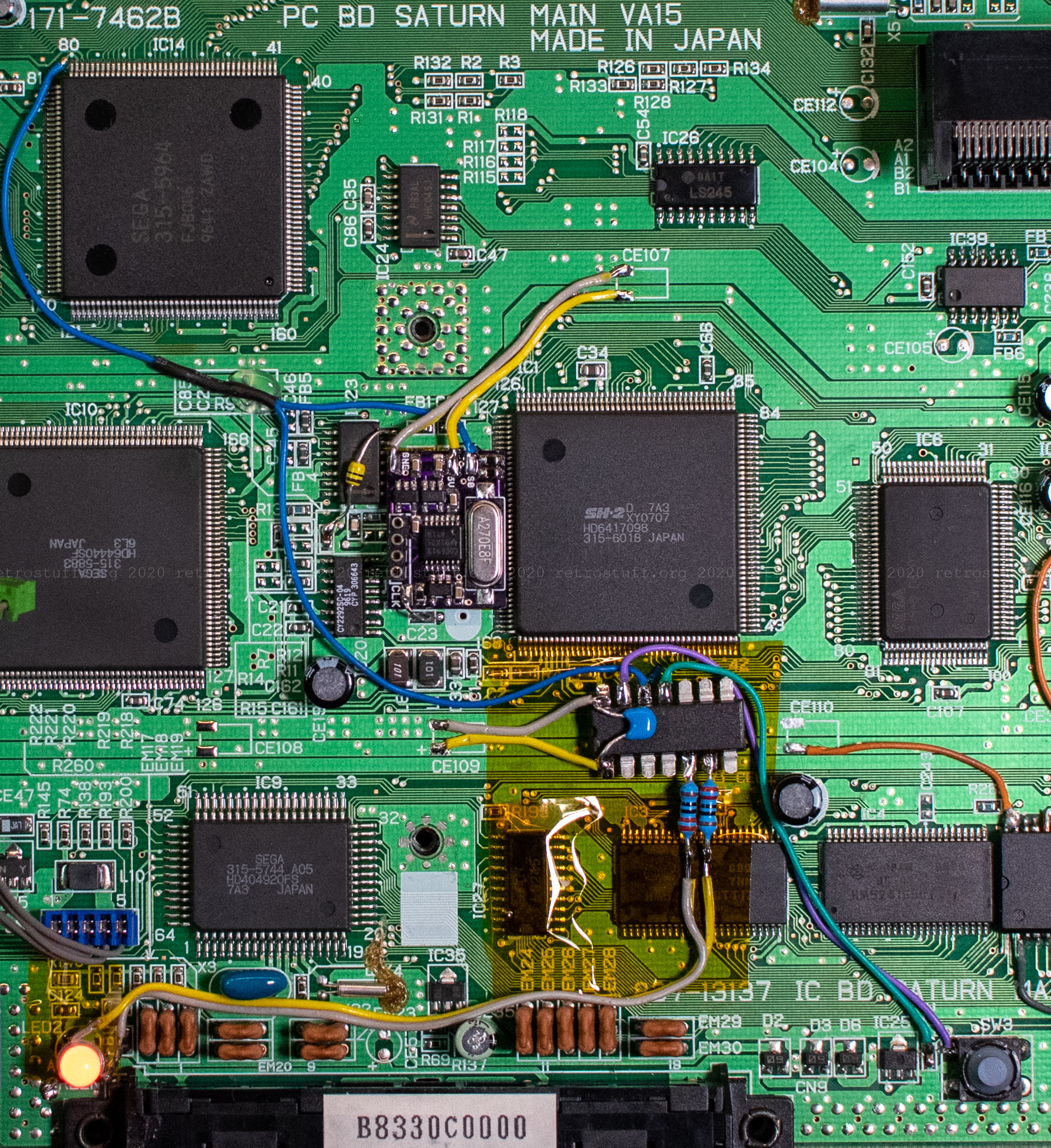
After testing the function of the PIC on a breadboard, I assembled everything directly on a piece of Kapton tape on the mainboard. I managed to re-use most components from the previous switchless mod but had to get rid of the stripboard, the socket and the long wires.
The now longest and most important wire goes from pin 12 of the PIC to pin 79 of the VDP2 (IC14); it switches between 50 and 60 Hz. I attached it to the via hole next to pin 80. There was no need to lift pin 79 because I had previously cut the trace above the via hole on the back of the mainboard. (Of course, I removed the fix again that I applied in the section “Starting over”.)
Finishing touches
After some more successful tests, I secured and covered the PIC with Kapton tape. Before assembling everything back together, I added the +5 V wire for the modchip again and crimped a Dupont connector onto it, for easier removal in the future. (Hint: Don’t forget the black plastic cover in the upper right before screwing the metal case back in.)

That concludes the Sega Saturn modifications for today. You can stop reading here, or continue to learn about something that won’t work.
Detour / DFO
Of course, this whole operation wasn’t finished on a single day. In-between, I took a detour because I thought it was a good idea to add a DFO (dual frequency oscillator) as well. I used the 5 V SMD DFO that I baked in my reflow oven a while ago and followed the NTSC Saturn instructions from the German Circuit-Board.
Again, I found that the frequencies were a bit lower than programmed – the same as what I experienced with the DIL-14 version in my CDI470. This time, I did not attempt to raise the frequencies because initial tests didn’t confuse my TV. However, as soon as the CD-ROM drive was connected, the Saturn showed some weird behaviour: The intro animation of the BIOS was skipped or stopped when in 50 Hz mode and it had trouble to recognize the discs. When booting in 60 Hz, everything was fine, but the game crashed as soon as I switched back to 50 Hz.
It turned out that frequency switching is only supported by very few Sega Saturn mainboards, and mine is not among them. This topic is explained in the DFO thread in the NFG forums. I have a couple of earlier PAL Saturns lying around and will attempt this modification again some other time.
Do you have a link on a guide to flash Sega Saturn Bios? I haven’t been able to find a guide yet.
All relevant links to get you started are in the article. I don’t know if there is another guide, sorry.
Nice work! I’m in the process of restoring a VA15 board as well, being sold in Brazil, it was converted to PAL-M from NTSC-J.
I’m getting it back to NTSC-J, but I need some help, and maybe you can help me. My board had an additional board soldered on CE102 and missing R142, with I don’t know it’s value, can you read it?
Also Jumpers JP1 and JP2 are altered as well, can you confirm me the JP1 are bridged and the right pads from both JP1 and JP2 are connected?
Thanks, and soon I hope to follow some of the same mods you did!
Thanks for the feedback!
R142 is a zero-ohm resistor (0). About JP1 and JP2: I can confirm that JP1 is bridged and that the right pads of JP1 and JP2 are connected.
Are you documenting your progress somewhere and also show the additional board on CE102?
Sorry for the long delay!
I’m not doing any kind of writeups, but I have some pictures of this conversion board and it’s instalation below.
https://drive.google.com/uc?id=1CD2wXtKrVmf5xBfGx7SDbP2uYKsd-WRN
https://drive.google.com/uc?id=1AL3cXxBNIXiA8bcKMPD0gKzPt-rXdmuZ
https://drive.google.com/uc?id=1NN4B_C5pXNu162v0bs1JPhg7nji-WVjw
https://drive.google.com/uc?id=1VxRcGeZvtCibEurwid4MTW02vh_W9E78
https://drive.google.com/uc?id=1BukBBq1TuoNc5moZtc3Zd2dDdD4yvxd_
https://drive.google.com/uc?id=1JTMdLcjHG2DTGWFmO2A14IJ0dXS-KTaS
Interesting, thanks for sharing! Did you manage to convert it back to normal?
Yes!
With your help I put everything back to stock. Now it’s outputting NTSC-J, but set to read US games.
Great!
Heya,
How did you combind multiple bios into one Chip?
Is it possible to switch between bios with a switch?
Hi, it’s explained in the grey text box (copy /B to combine the files). You could add a switch to pin 2 (centre), +5V (left) and GND (right).