
This is a follow-up to the modifications I did to a NTSC VA15 Saturn. In this article, I will implement the following Sega Saturn (PAL VA3) modifications: Region-free BIOS, FRAM, and a 50/60 Hz switch (SW4).
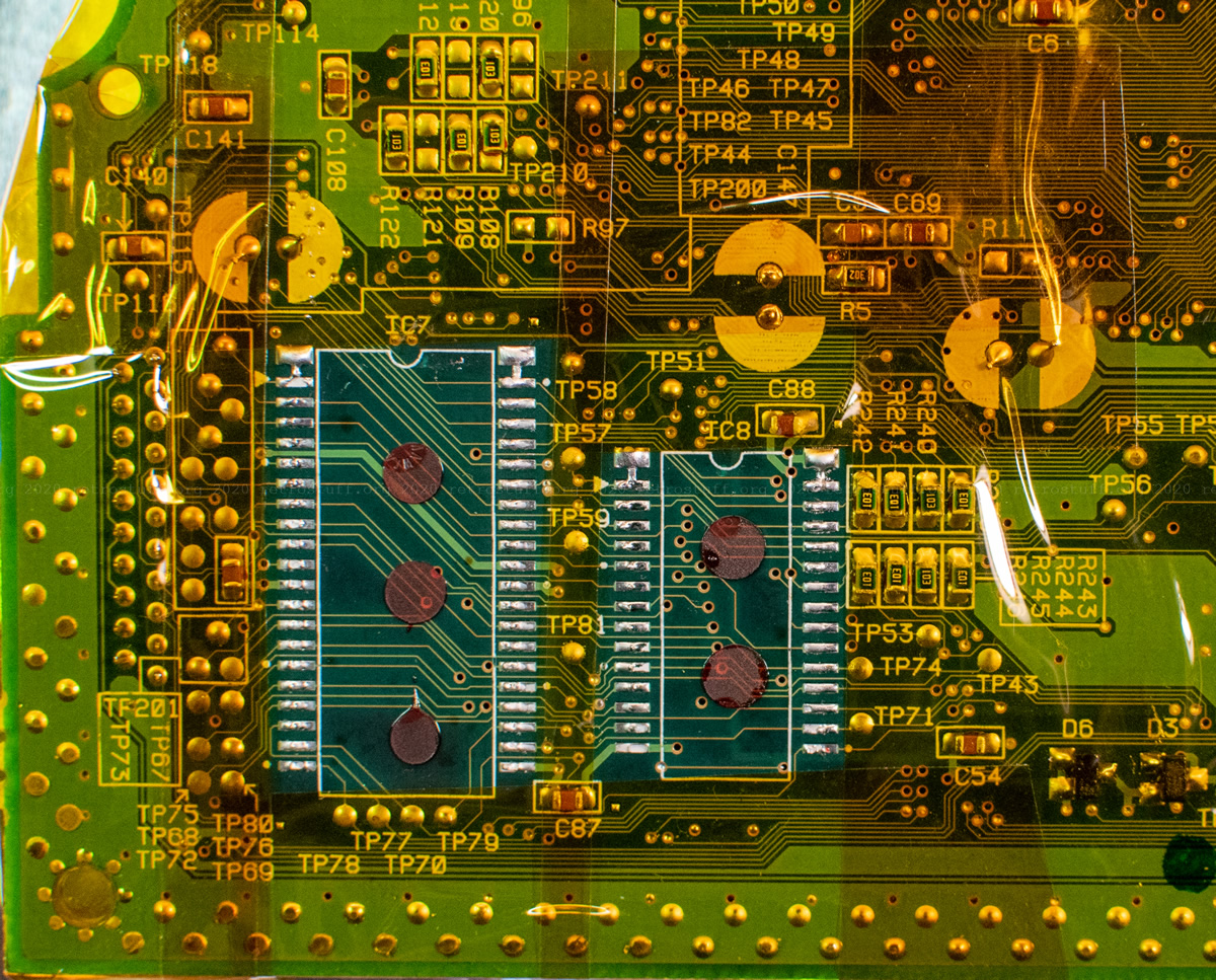
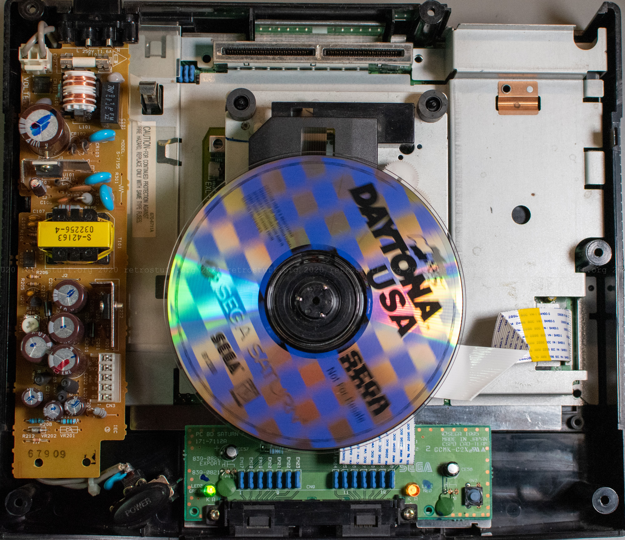
After finishing the last article, I took three broken PAL Saturns that I had lying around apart to see what I could repair and modify next: A Model 1 with VA1 mainboard, a Model 1 with VA3 (aka “PAL VA SD”) mainboard and an almost identical Model 2 (VA5, also “PAL VA SD”). I had only one working Type-B power supply, so I had to make a choice. I went with the VA3 Model 1 because the mainboard was in the best condition and only needed a working disc drive and power cable, reset button stick, power suppy and some cleaning. This is how is looked before:
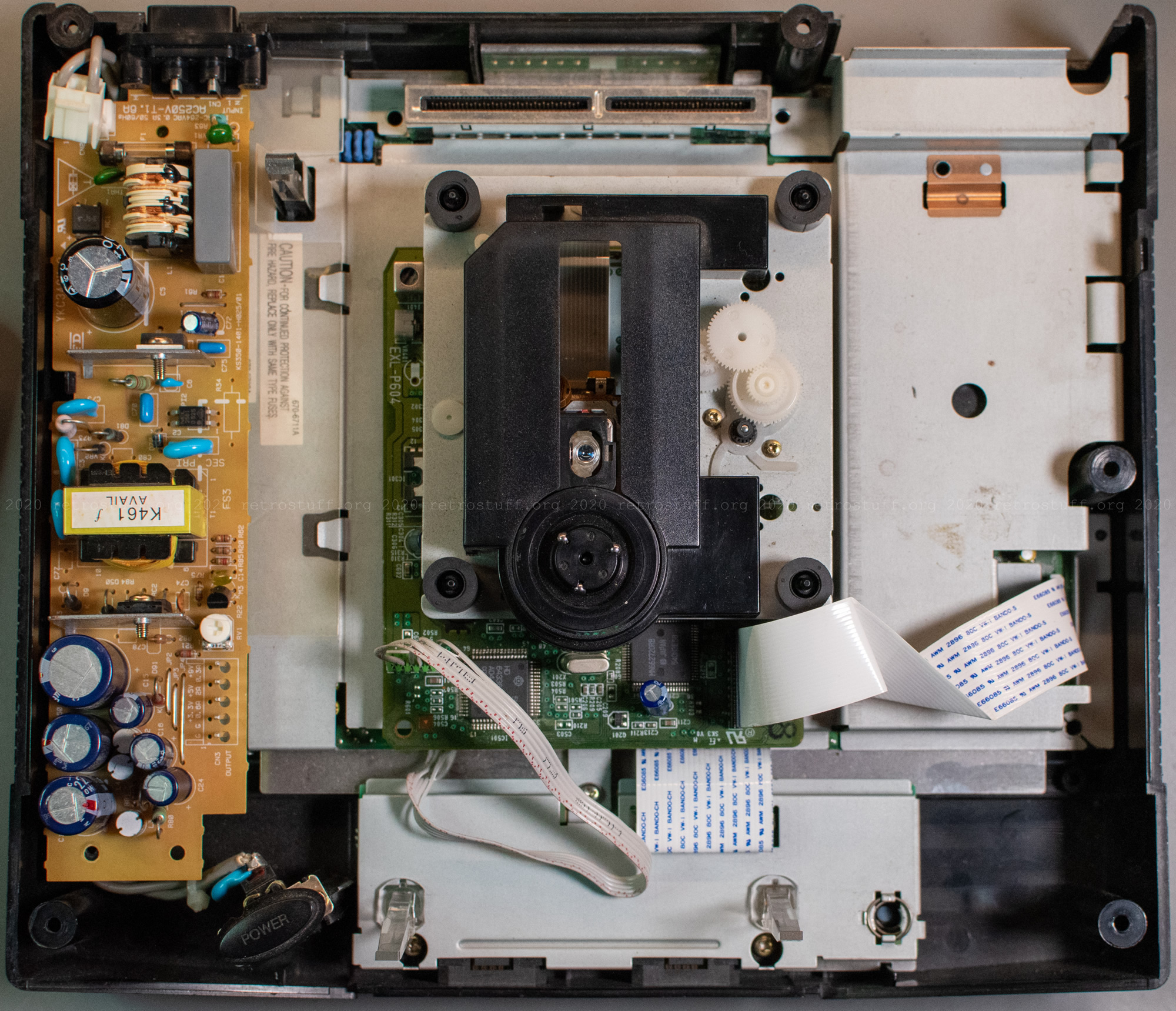
After I replaced the power cable of the disc drive and did some tests, I was ready to modify the mainboard.
Region-free BIOS and FRAM modification
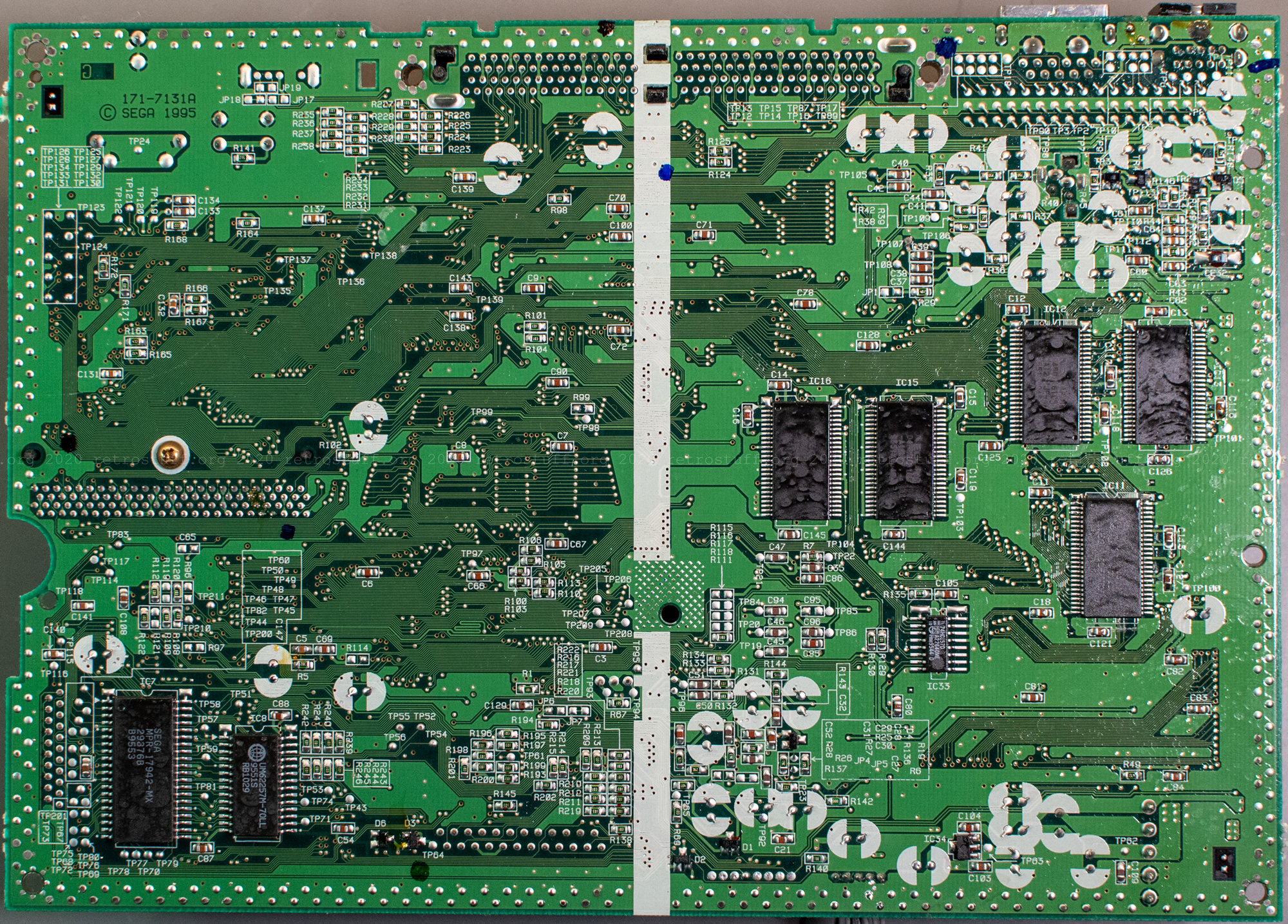
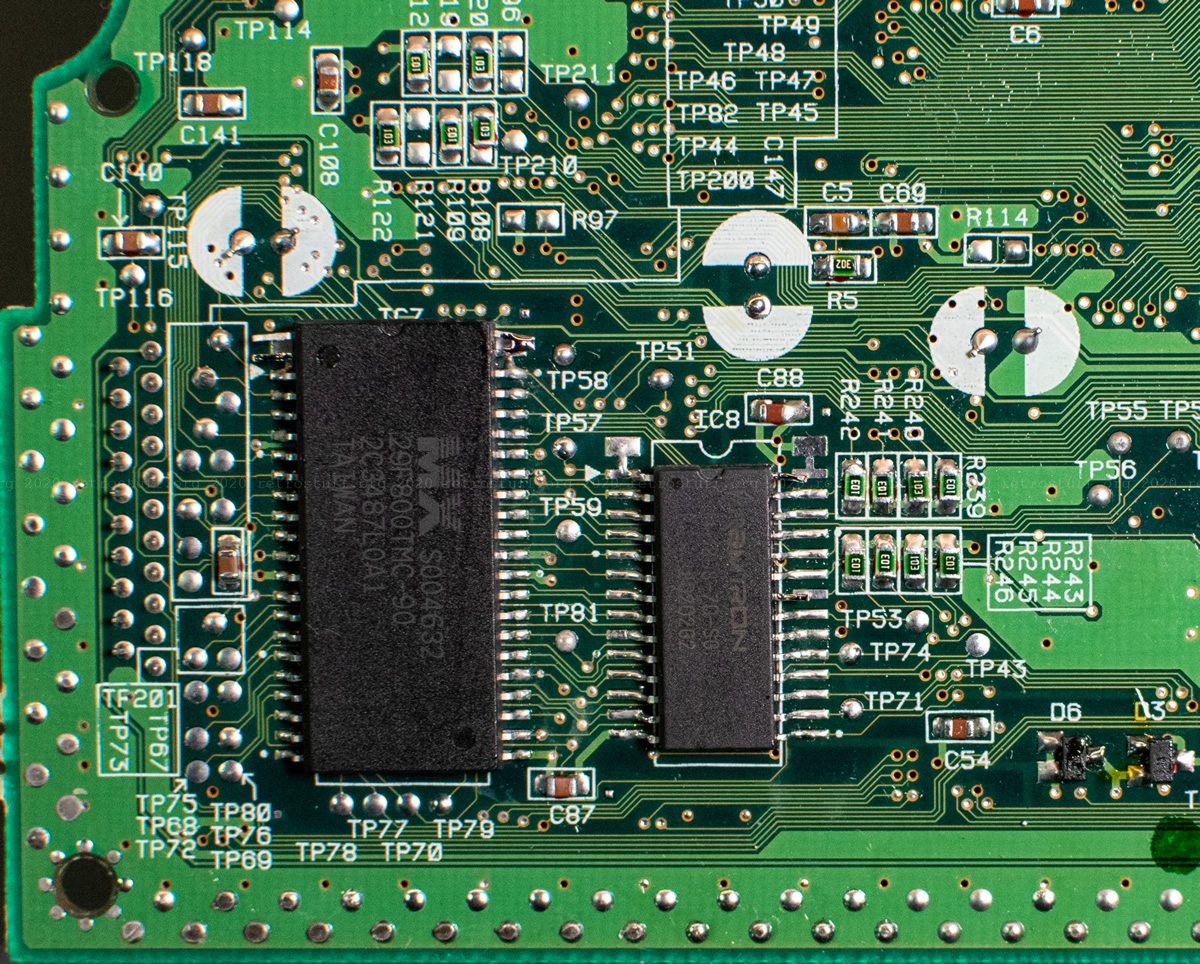
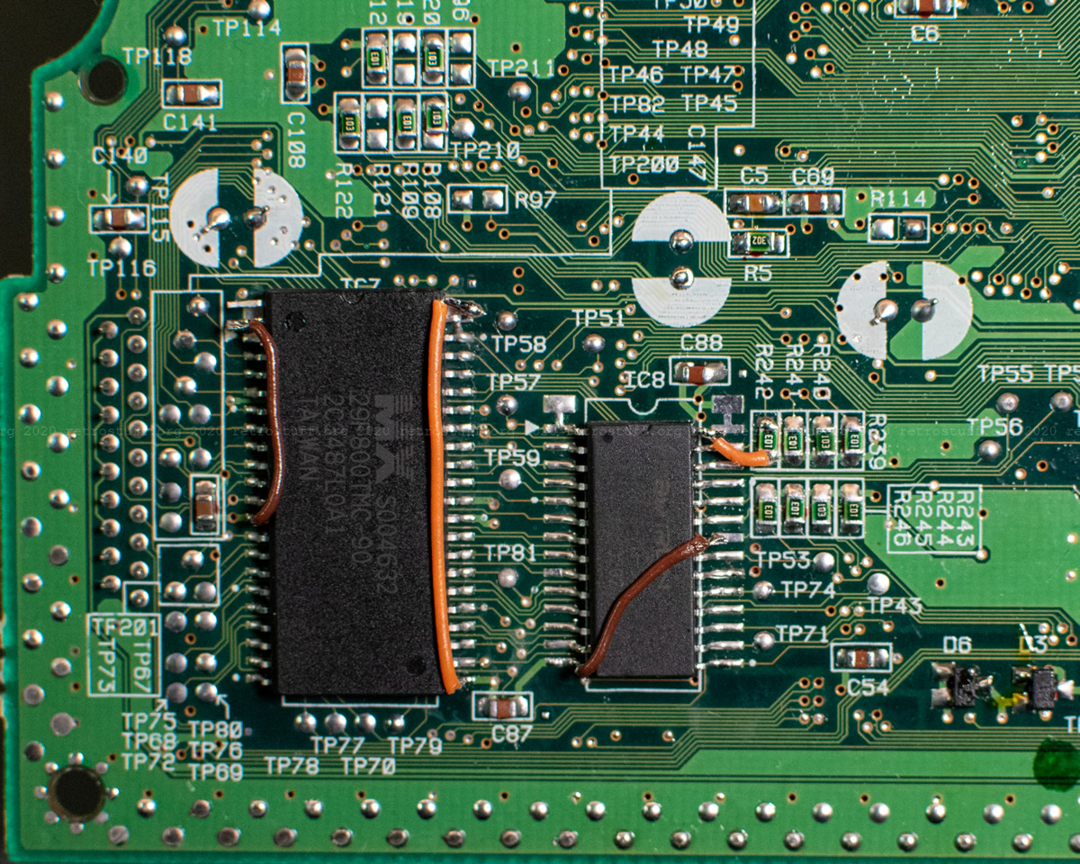
Both chips are next to each other on the lower left on the back of the mainboard. I removed and replaced them in a single session. But first, some explanation (parts are taken from the previous article).
Explanation / preparing the flash memory chip
The region-free BIOS has the region lockout removed and allows you to play (original) games from all regions. There is an excellent tutorial by mmmonkey; you can find the needed files there as well.
Usually, the region-free BIOS file is duplicated, byte-swapped and then written onto the chip (Macronix MX29F800TMC-90).
Instead of duplicating it, I combined the region-free and the original U/E 1.01a BIOS file (copy /B eur v1 regionfree.bin + Bios Saturn 1.01a (U) [!].bin newbios.bin). If for whatever reason the region-free BIOS didn’t work, I could still fall back to the original BIOS by connecting address line A18 (pin 2) to +5 V instead to GND.
Hint: It is also possible to combine two different versions, e.g. EU/US 1.01a with JP 1.01 or the more exotic GameNavi HiSaturn 1.03 BIOS to switch between different startup animations.
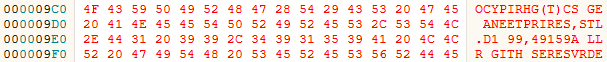
To write the combined BIOS file, you’ll need a programmer that is capable of handling 16-bit flash memory chips with 44 pins and a SOP-44 adapter. The software of the programmer most likely has a function to swap the bytes. If done correctly, the copyright string looks like this: OCYPIRHG(T).
My programmer (Batronix BX48 Batego II) did not have a driver for the replacement chip, but the driver for the newer, pin-compatible variant MX29F800CTMI-90 worked fine.
Explanation FRAM modification
The Sega Saturn has a power-hungry RTC. When the battery is empty, not only are the date/time and language settings lost, but also all game save files. To prevent this, you can replace the battery-backed SRAM with non-volatile FRAM. The RTC will still suck the CR2032 battery dry and ask for date/time and language settings whenever that has happened, but the internal memory will be safe.
There are two articles on RetroRGB that explain in detail how it works and basic instructions on the Wolfsoft blog.
Removing and replacing the chips
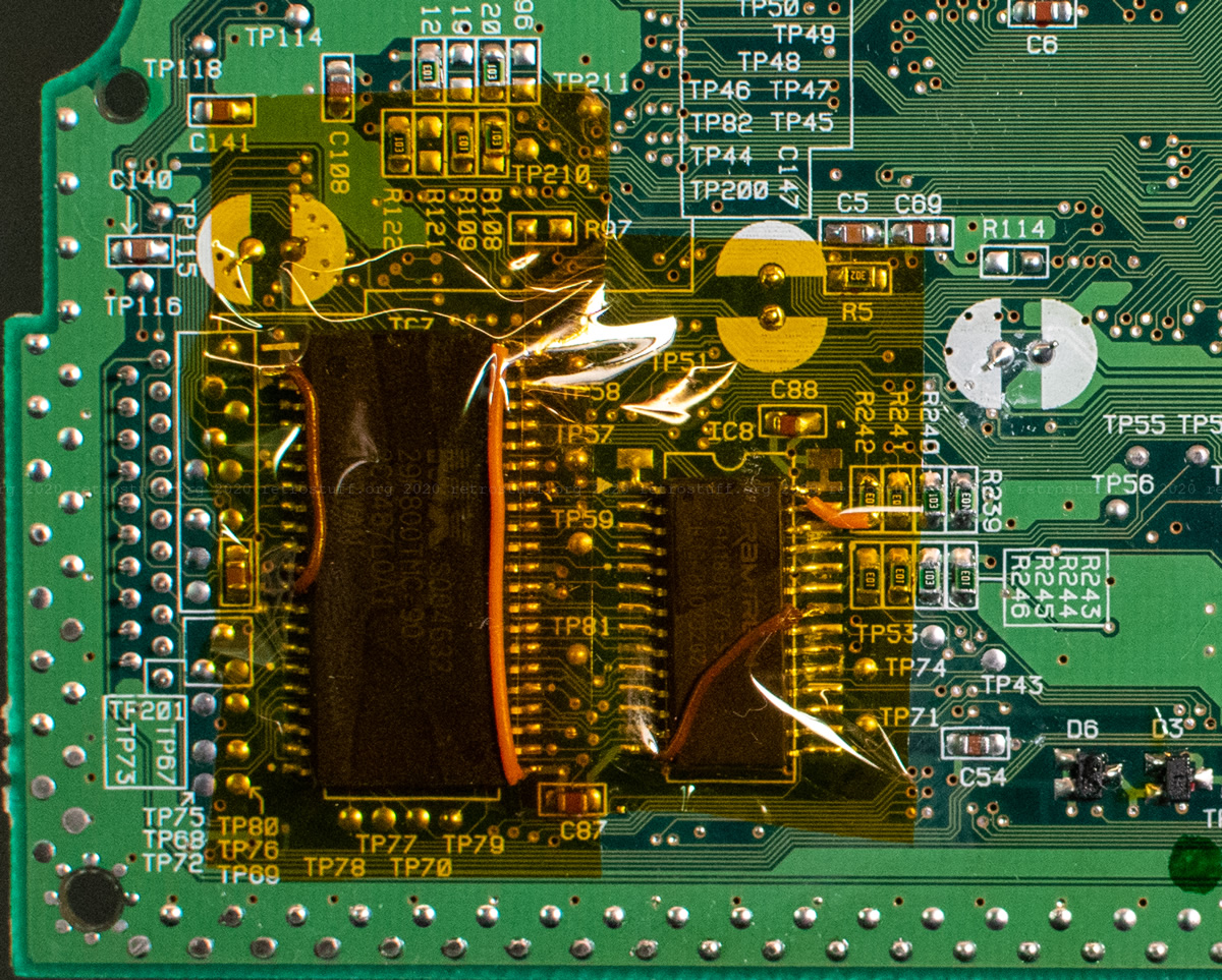
This was quite easy with the right tools (hot air station and plenty of flux). I protected the surrounding area with Kapton tape to prevent other components from getting loose and flying away.

Each chip took a couple of minutes; not only the solder needed to be heated but also the glue that was underneath the chips. The blobs wouldn’t go away, even after cleaning up the area.

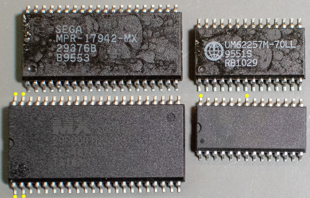
Let’s have a look at all four chips to see the different footprints/sizes: The old BIOS (top left) is smaller than the new flash memory (bottom left) and the old SRAM (top right) is larger than the new FRAM (bottom right). The legs marked with a yellow dot need to be bent up / straightened.
I aligned the chips on the footprints and soldered them with plenty of flux and lead-free solder.
These are the closest connection points for +5 V and GND:
Flash memory
Connect pin 2 to pin 13 (GND) and pins 43+44 to pin 23 (+5 V).
(Connect pin 2 to 43+44+23 instead if you want to use the second BIOS file that’s on the chip.)
FRAM
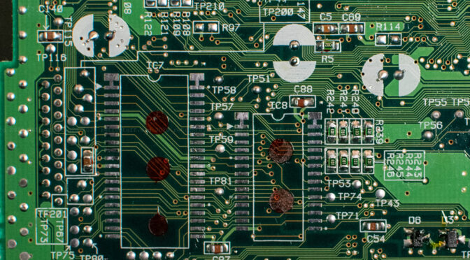
Connect pin 22 to pin 14 (GND) and pin 28 to the lower end of resistor R242.
After this was done, I covered both chips with Kapton tape.
Extensive tests with games from other regions were successful.
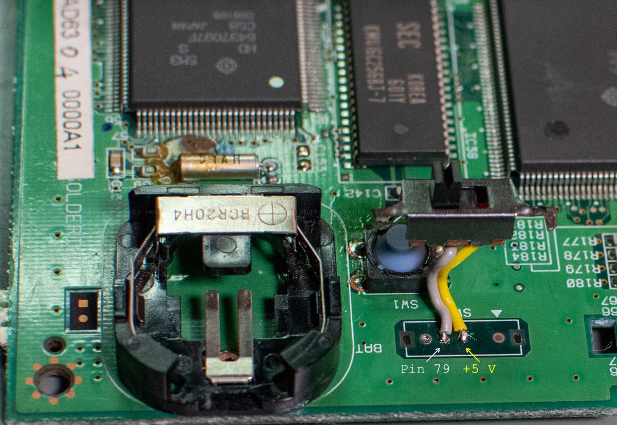
50/60 Hz switch (SW4)
If you are expecting something fancy now, you will probably be disappointed. Of course, I announced that I would attempt to add a DFO (dual frequency oscillator). But, after comparing my mainboards with the explanation in the DFO thread in the NFG forums, I decided against it, even if it would have been possible with some extra wires.
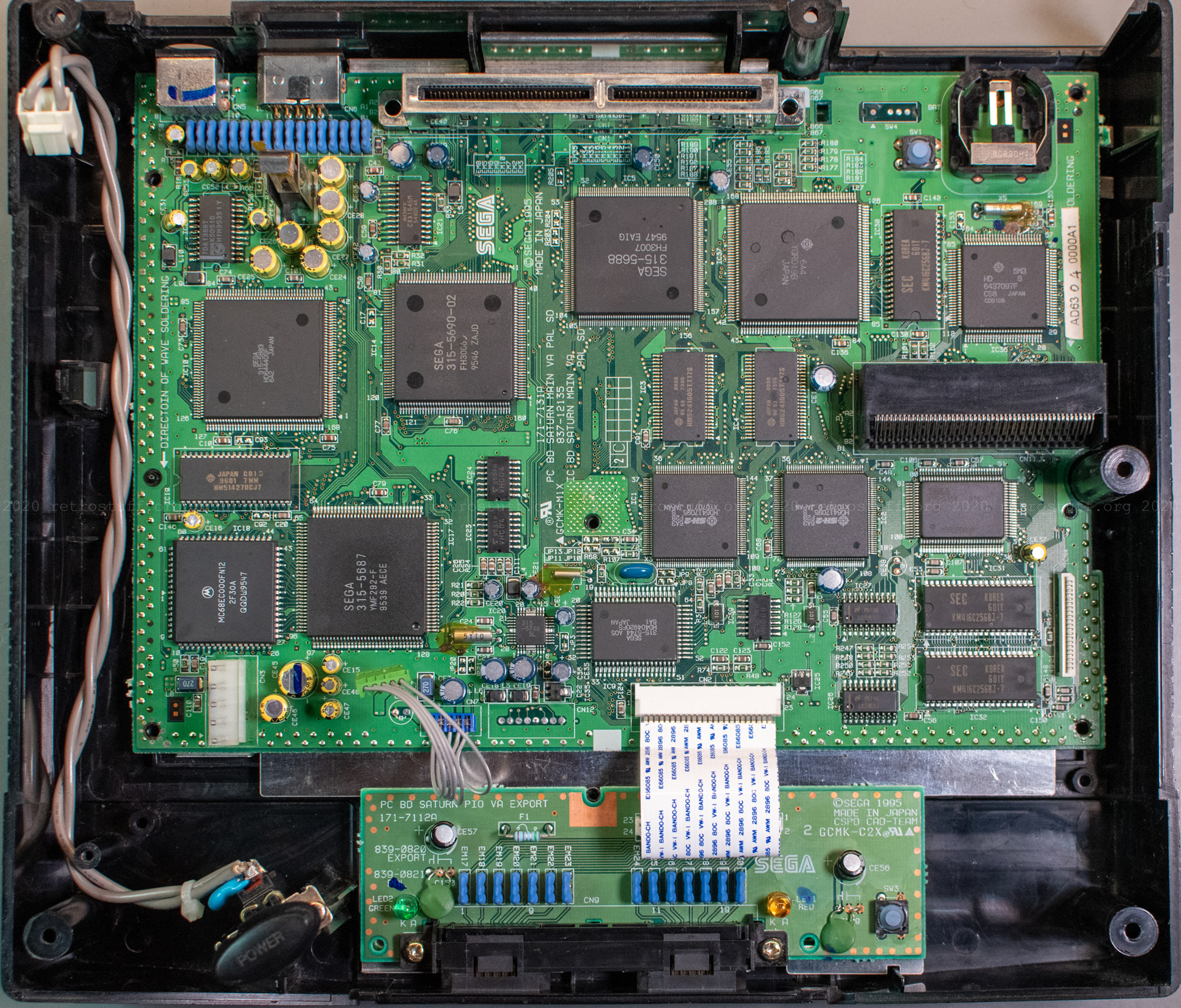
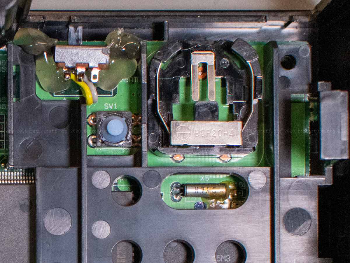
Instead, I went for a much simpler solution: “PAL VA SD” mainboards can be easily switched between 50 and 60 Hz by adding the switch “SW4” next to the battery and the reset button. You could also bridge the two pins in the middle for permanent 60 Hz mode – the left pin is connected to pin 79 of the VDP2 (IC14) and the right pin is connected to +5 V. There is no need to lift any pins and it can even be done without opening the console, if you are in a hurry.
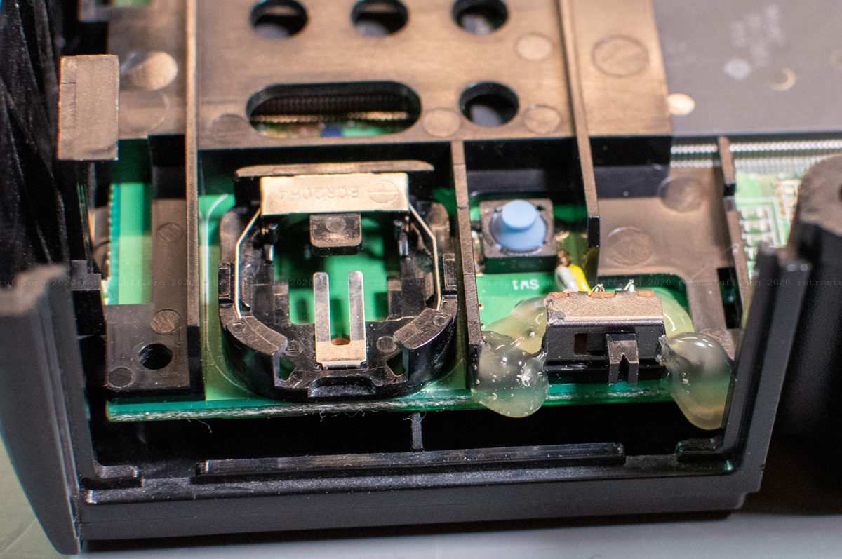
The only small switch that I had available was the type that I also used for some for my CD-i player modifications. I cut out parts of the sides and bent the remains of the screw holes down so that it can sit on the black plastic cover without moving inside.

Then, I fixed everything with hot glue (actually, low melt glue), taking care that no glue went inside the switch.
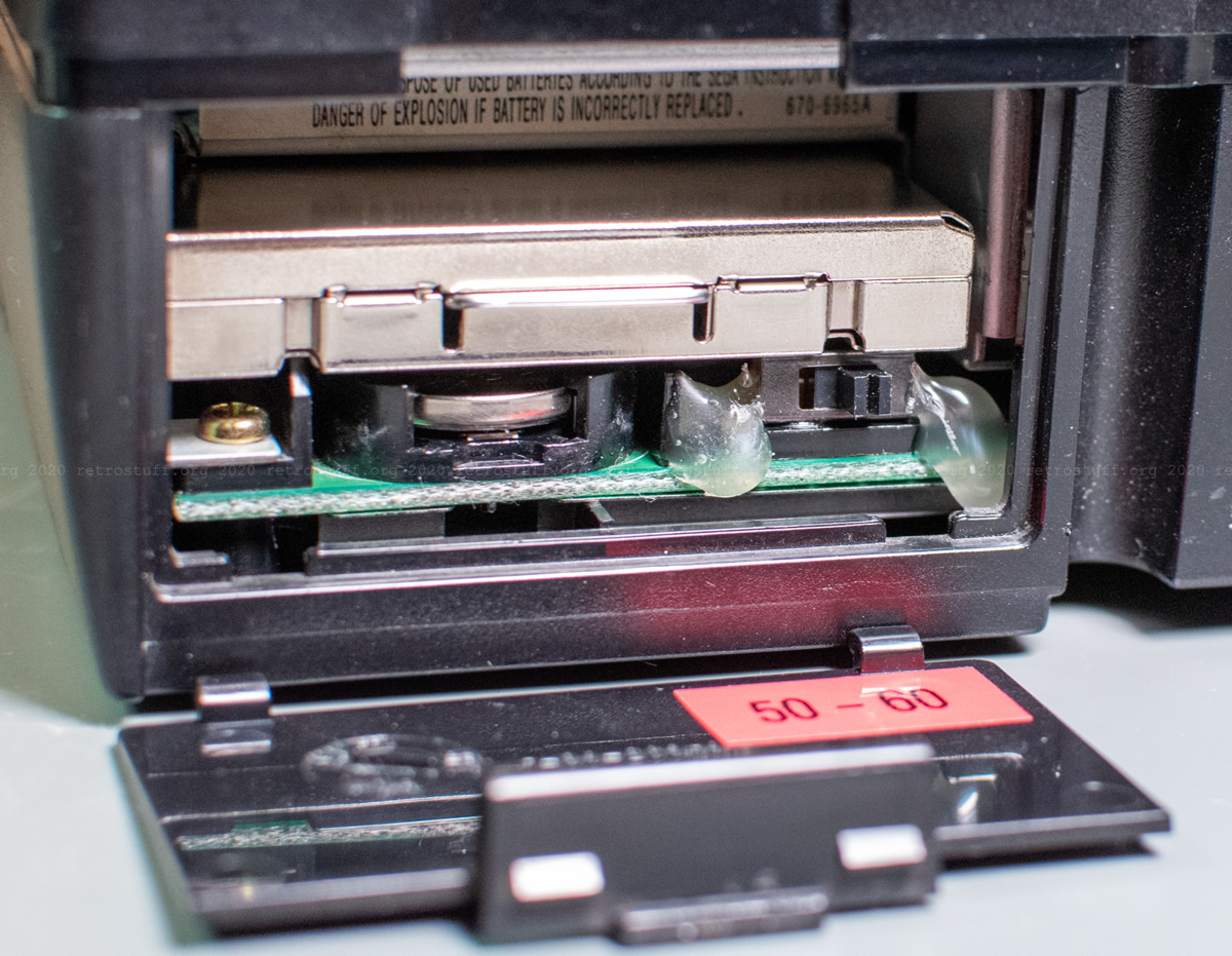
It isn’t pretty, but it meets all of my requirements:
1) The switch needs to be easy to access.
2) It has to be small enough to fit between the black plastic cover, the Video CD Card and the cover of the battery compartment.
3) The modification should be easily undone and must not leave any traces or holes in the case/cover.
Hi so connecting the two pins just with solder or better with wire?
That is entirely up to you. It’s probably easier with a piece of a resistor leg.
Thanks for the quick response. Ok cheers for that.
hi,
I recently modded my old pal round button Saturn va SD fram, bios and switch, anyway booted and everything is working fine, after about an half hour, I decided to switch the switch, is did this while powered up and bam, screen went blank, now that is all I gwt, no audio, if I put a ce in it just spins and nothing happens, any ideas?
thanks heaps 😊
When you switch it back, does everything go back to normal?
If not, check if you really have the right board revision and if there weren’t any previous modifications. Check voltages, check every area that you touched, undo steps if needed.