
After finishing the repairs on my CPS2 in April, I had already some more additions in mind:
- The CPS2 digital AV interface which adds an HDMI port to the CPS2. It was invented by marqs, who also brought us the OSSC, and is simply speaking a small internal version of it.
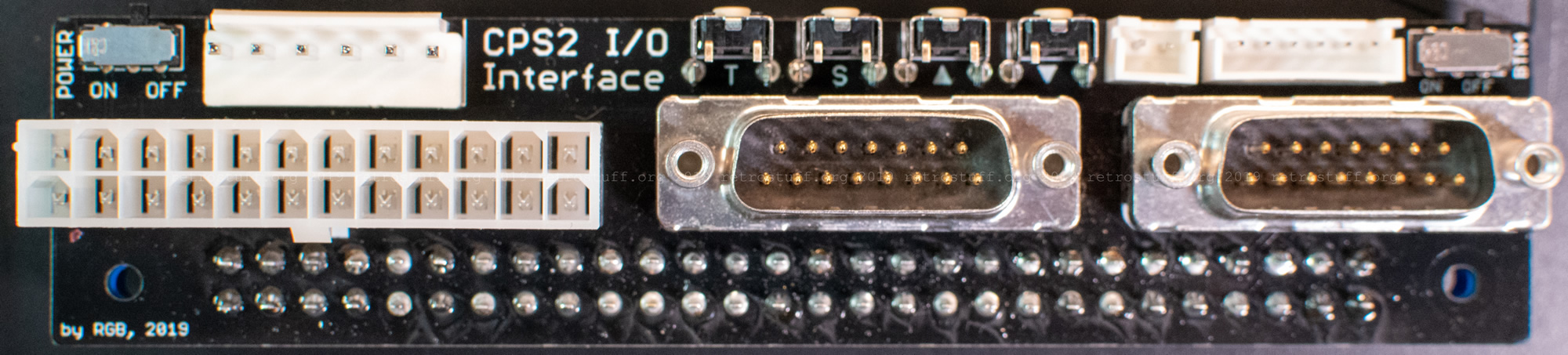
- The CPS2 I/O interface with matching kick harness to remove the need for a SuperGun.
I had already ordered the digital AV interface kit from VideoGamePerfection.com in the beginning of the year and was only waiting for the I/O interface to get started. Last month, it finally arrived. Also on the picture: a home-made kick harness and a RG174 coaxial cable.

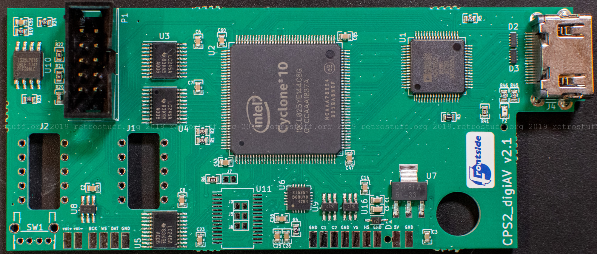
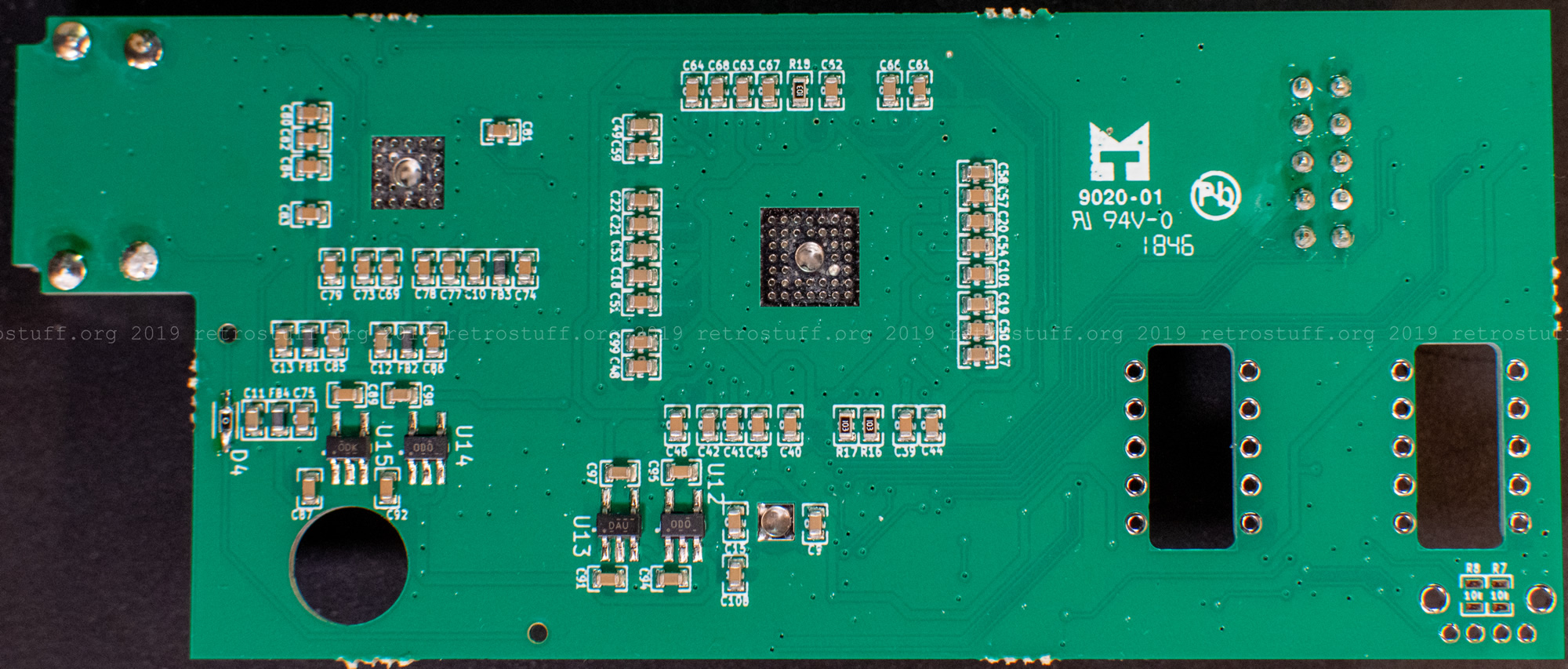
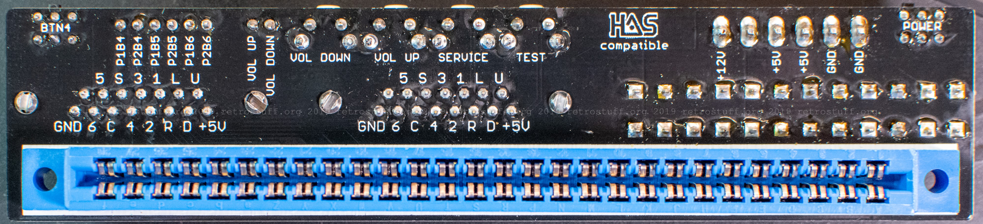
Detailed pictures of the interface PCBs:
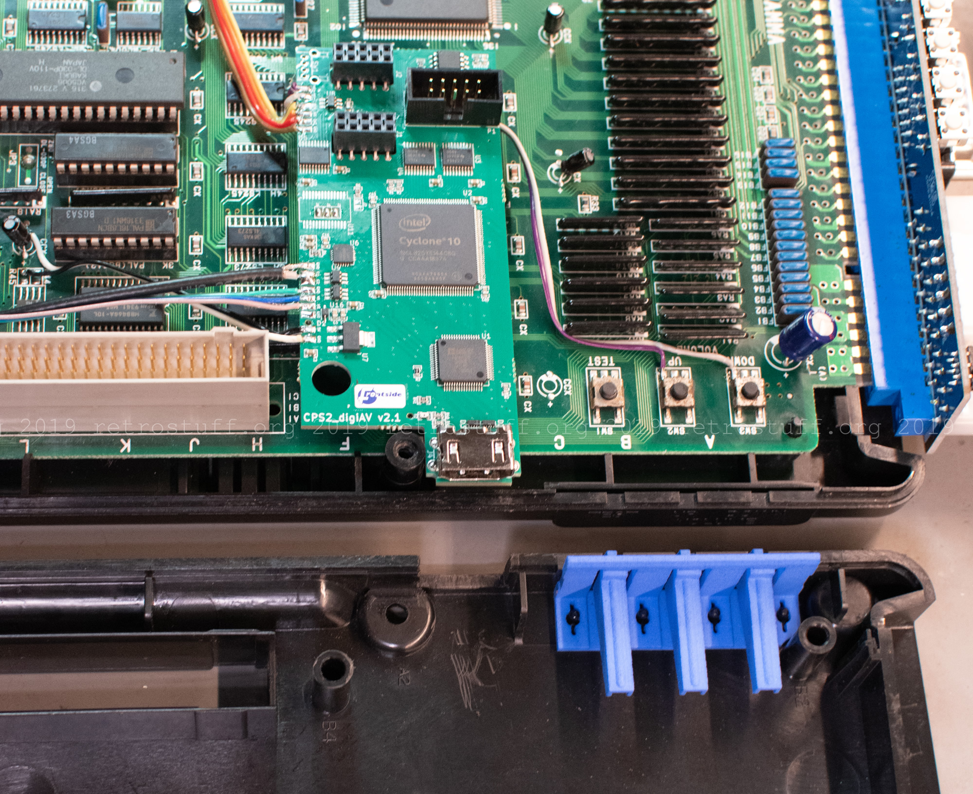
CPS2 digital AV interface installation
The installation is not too hard, although the installation instructions (PDF document) can be quite confusing. Additional pictures and hints in the CPS2 I/O interface thread proved very helpful in figuring it out.
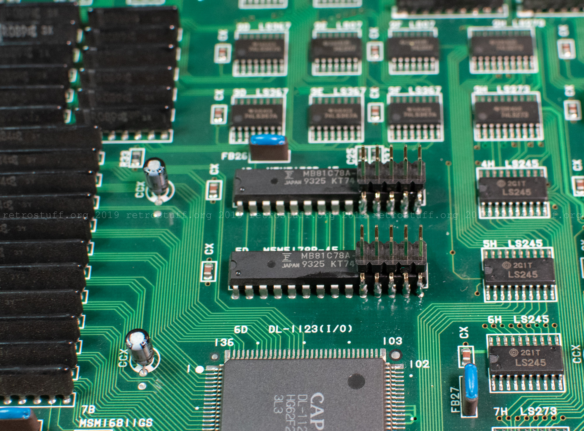
First, solder the 2×5 headers onto the M5M RAM chips.
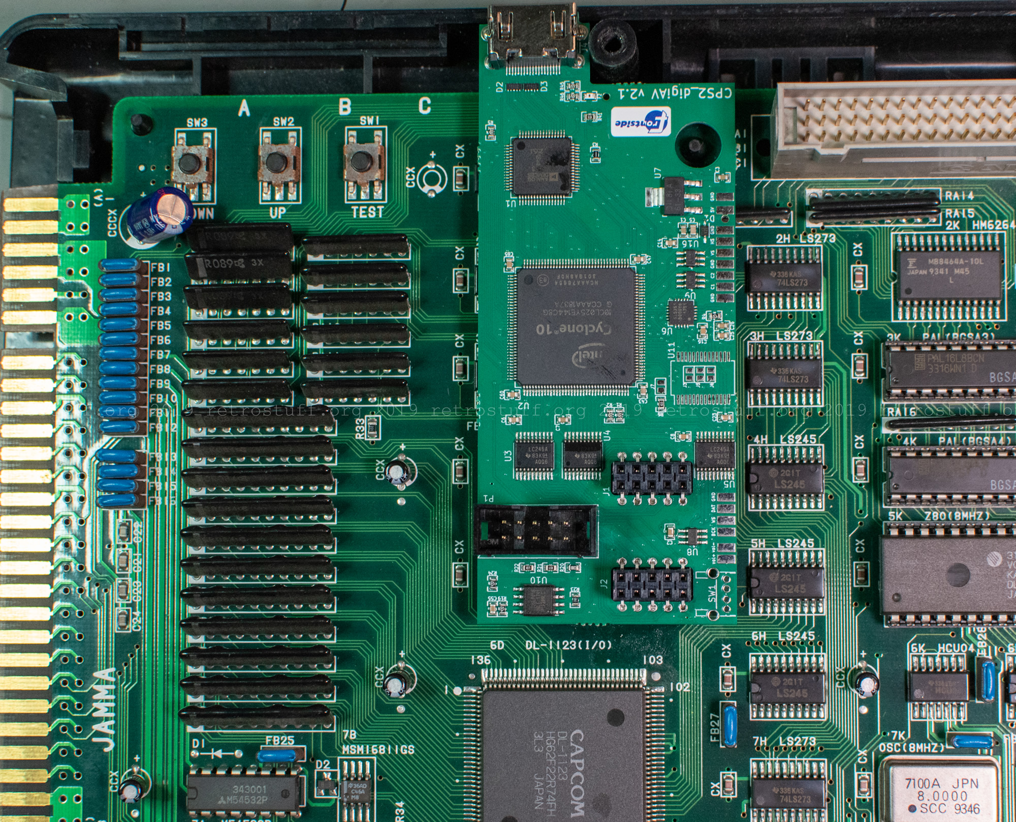
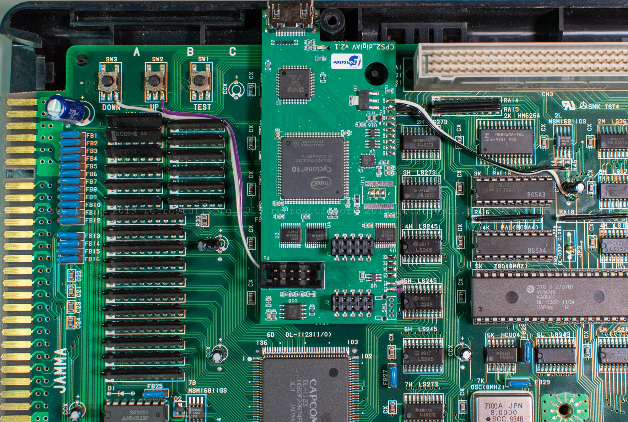
Next, place the 2×5 sockets onto the interface PCB and solder them from the back. Then place the PCB onto the headers and see if it fits. The PCB end with the HDMI port has to sit flush on the frame of the bottom cover, and you should see the black plastic pin in the centre of the hole. The complementary piece from the top cover will later go through the hole and keep the PCB in place.
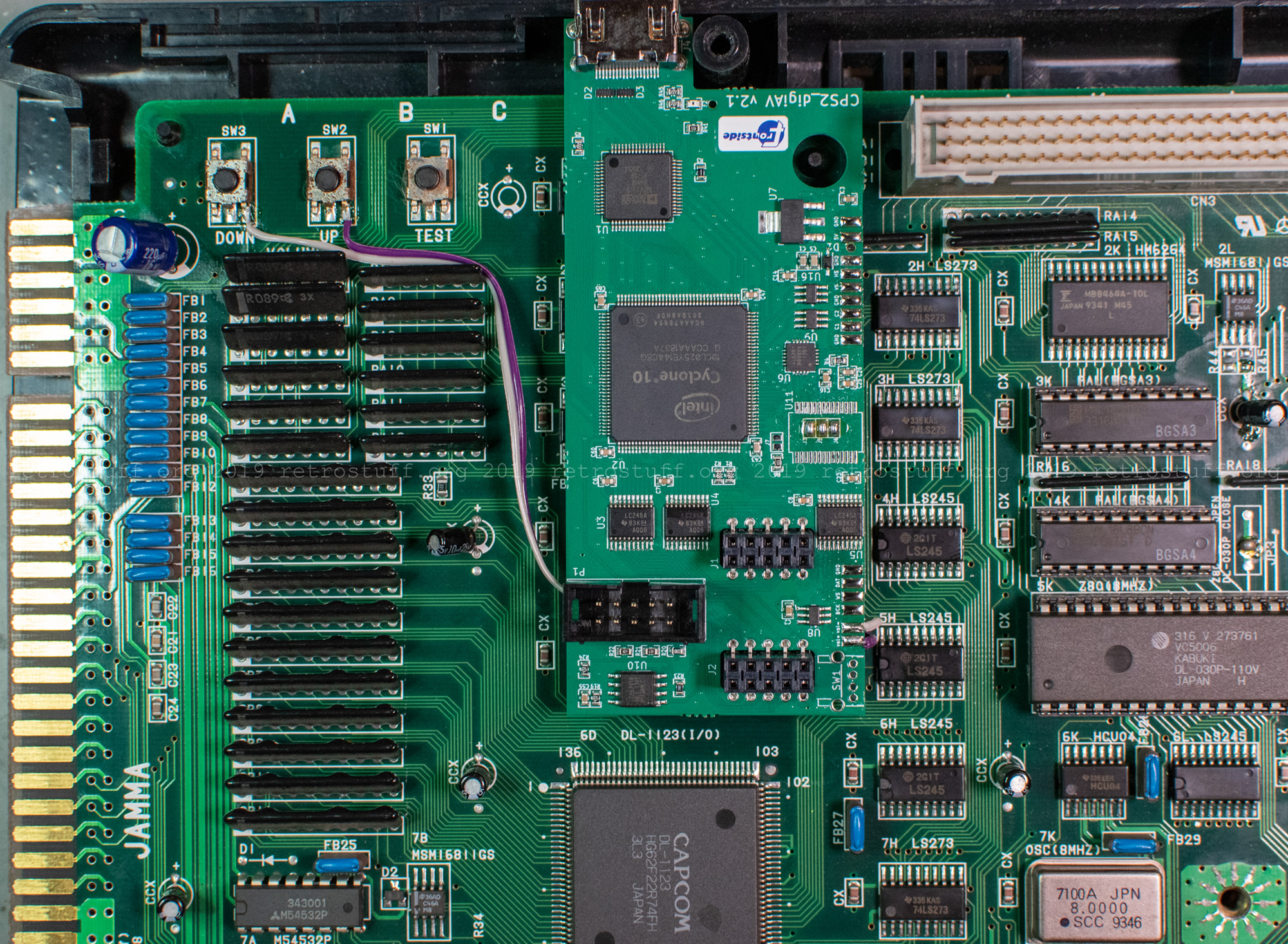
Remove the PCB again and solder the wires to the volume buttons. These will later change the vertical offset and enable/disable the scanlines. Now is also a good time to close the three jumpers J3, J5 and J6 within the U11 footprint, if not already done.
Put the PCB back onto the headers and align it again. +5V and GND can be tapped from any of the nearby electrolyte capacitors marked CCX. Note: the digital AV interface draws about 200 mA.
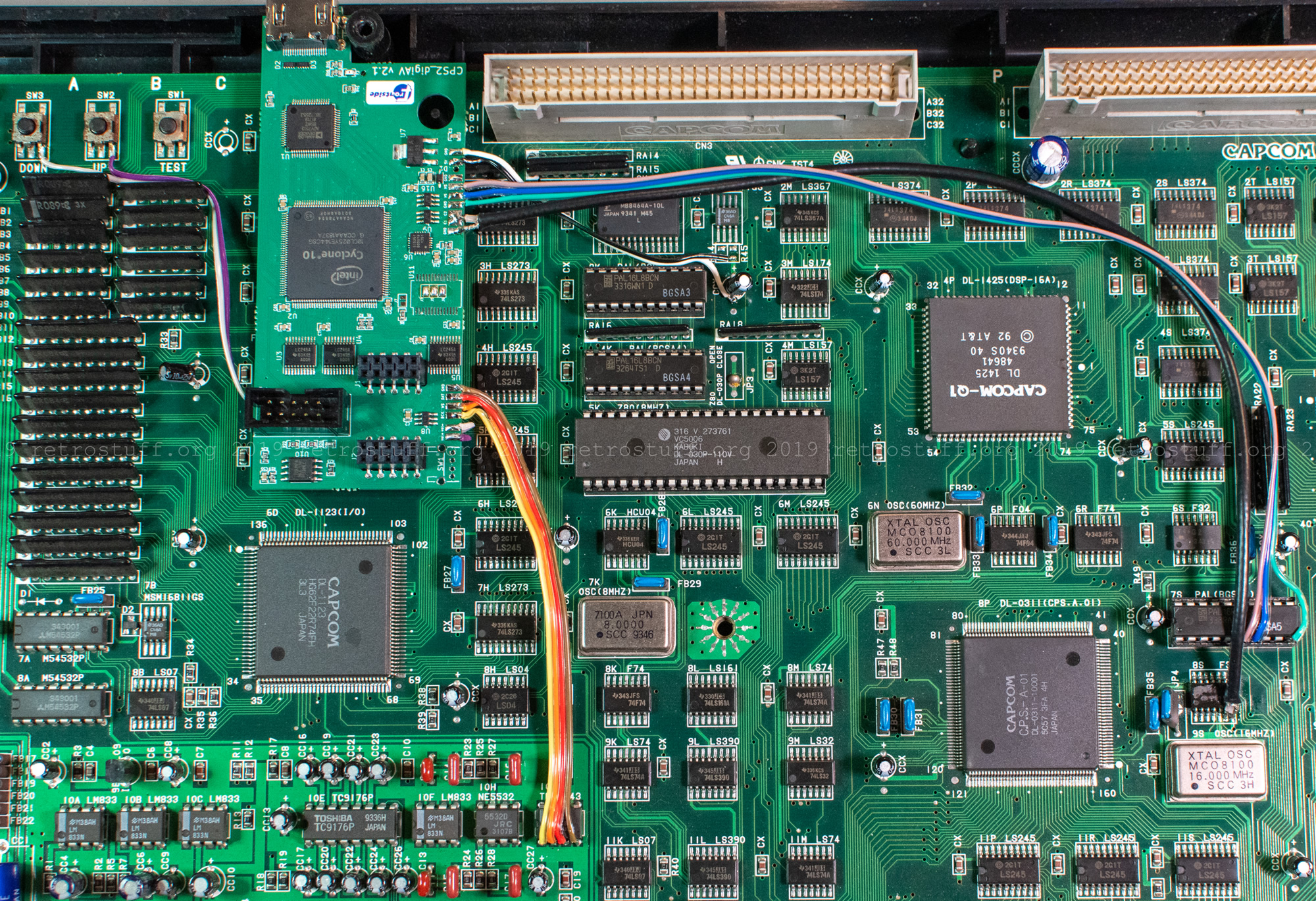
Route ribbon cables to TDA1543 for audio and PAL (BGSA5) for sync signals.
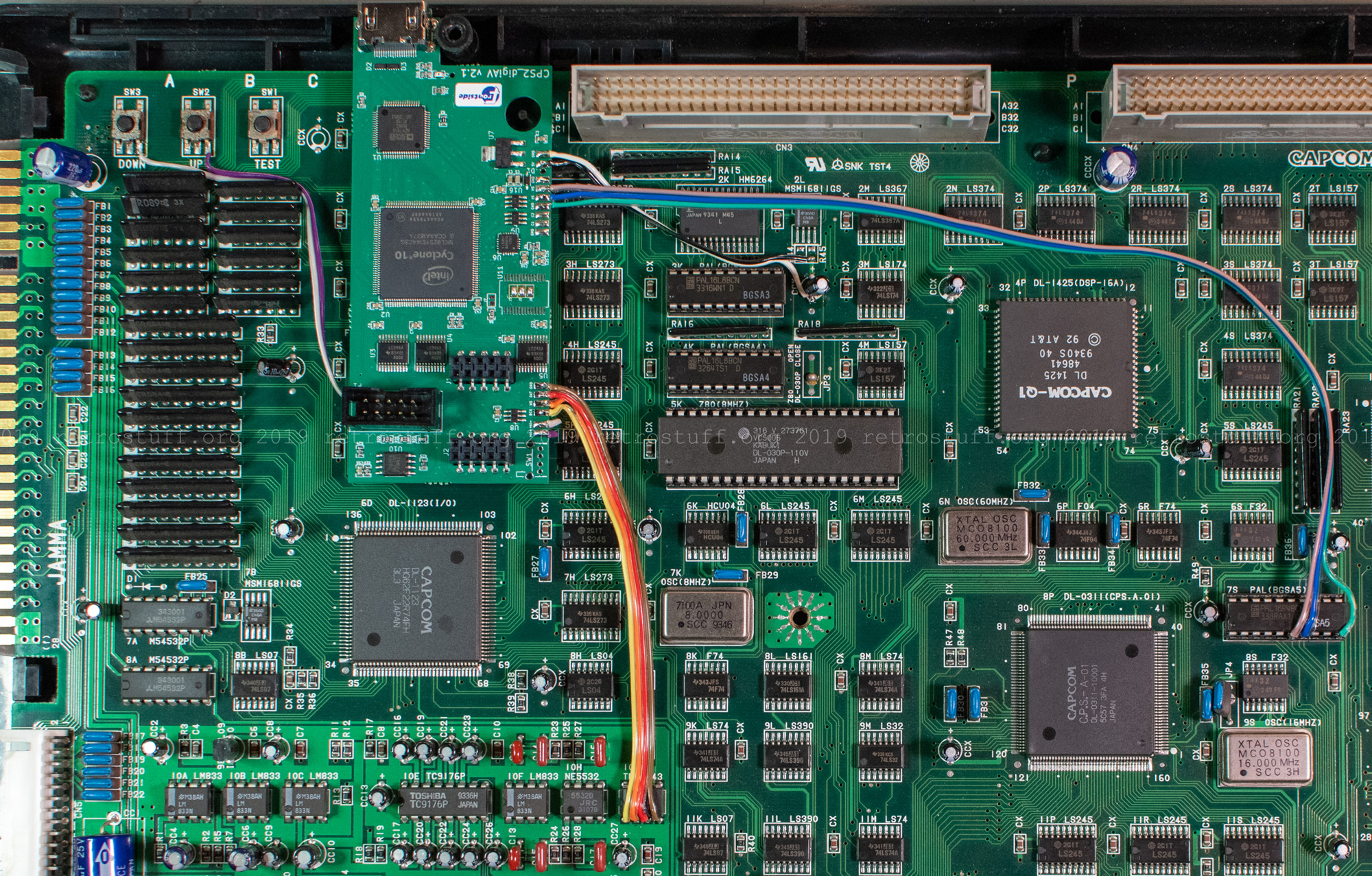
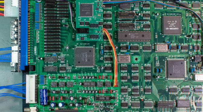
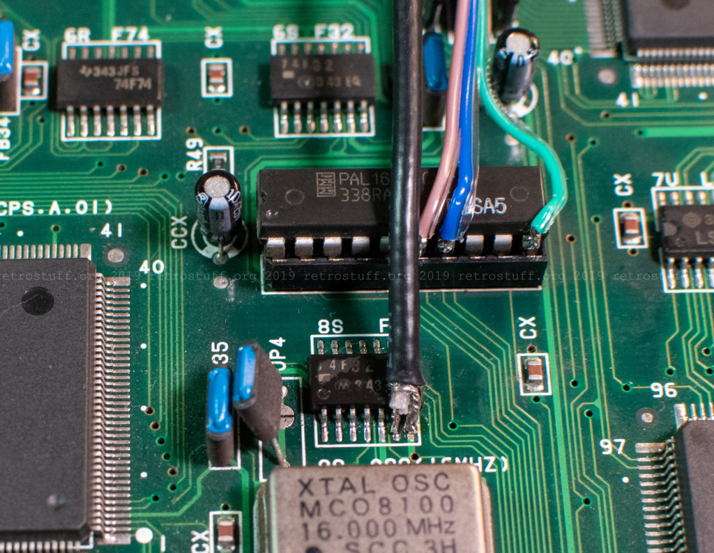
I tapped the clock signal from the 8S F32 chip next to the 16 MHz oscillator. A coaxial cable (e.g. RG174) is mandatory. Solder the inner wire to both pads on the interface PCB (C1 and C2).
Here is a close-up of the clock and sync signal cables. The coaxial cable is very stiff, so I secured it with hot glue before closing the case to avoid it from accidentally damaging the chip or its legs.
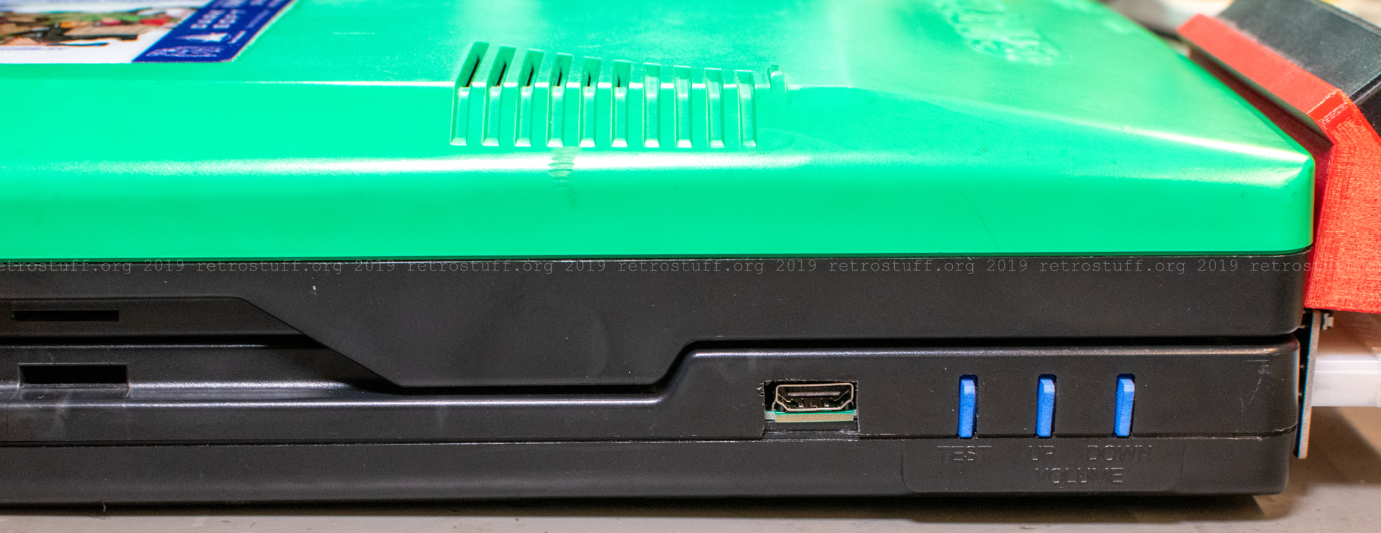
Finally, cut a hole for the HDMI port in the top cover next to the buttons. I did it with a Dremel and accidentally cut out too much because the plastic is quite soft. There is no need for power tools, a sharp knife and a file will do the job just fine.
CPS2 I/O interface installation
The I/O interface installation is pretty straightforward, just plug it into the JAMMA connector and attach the cables for the kick harness.
I am not happy about the final result though. The printed holster of the LCD selector sits right on top of the I/O interface buttons and switches and obstructs the access. More severe is that the buttons are accidentally pushed when touching the holster or the whole unit – which can become a problem when suddenly the test mode is entered while playing a game.
I’ll have to find a solution for this at a later time. I will also shorten the cables to the kick harness then.
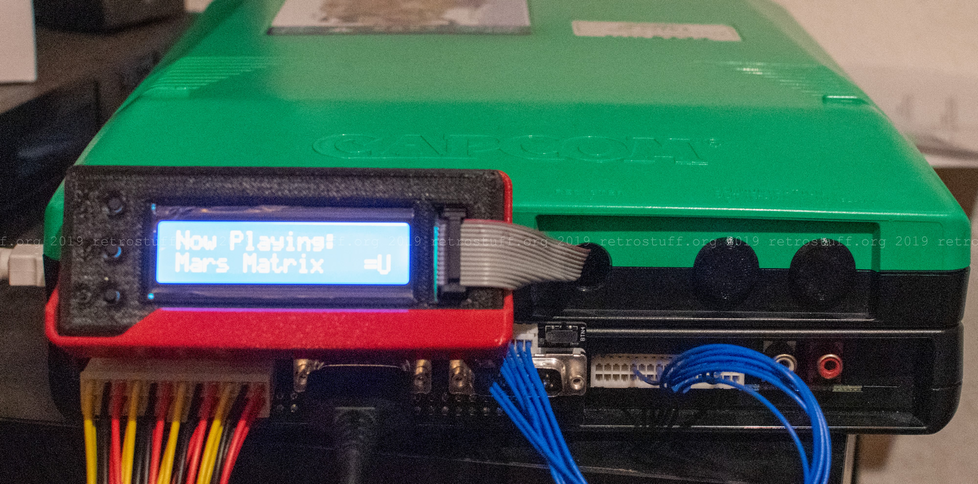
Also seen on the picture above: Printed caps that close the holes in the B Board.
Quality
The digital AV interface adds another level of lossless digital quality and also simplicity when compared to my previous setup with SuperGun, OSSC and custom SCART cable (to tap stereo audio from the cinch connectors of the CPS2).
The video output size is fixed at 1080p which is the same as the OSSC in Line5x mode / default 1920×1080 format. This means that 4 lines are missing on both top and bottom of the screen. The vertical offset can be adjusted in 9 steps with Volume – button, but there are always 8 lines missing in total. This isn’t a problem for the OSSC, as the Line5x format can be set 1920×1200. For the digital AV interface, this is not possible.
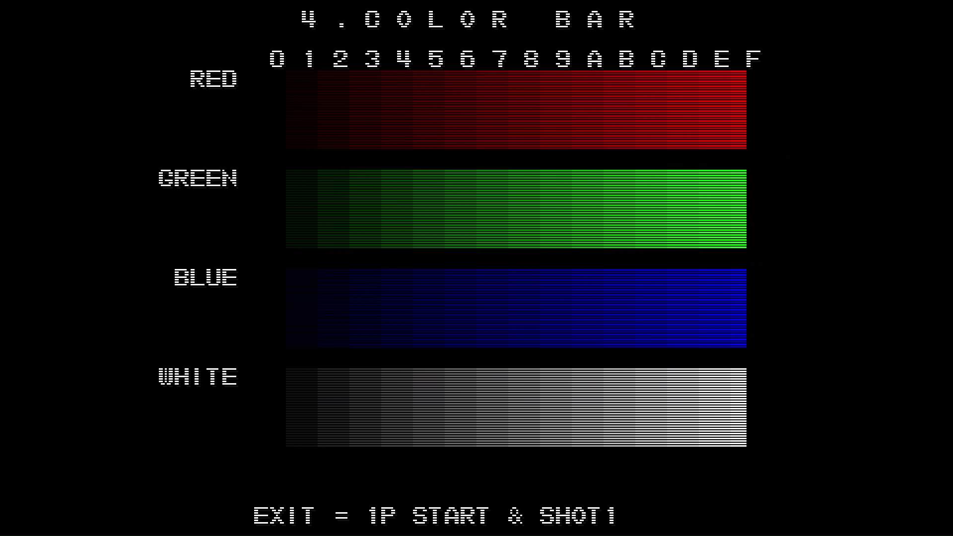
Another setting that is fixed: the intensity of the scanlines. They can be either enabled or disabled with the Volume + button.
I’m looking forward to future firmware releases that hopefully give more choices for output format and scanline intensity.
Update (2020-03-29): A new firmware that enables changing the output resolutions has been released.
Update (2020-10-23): A new firmware with an OSD and more settings and features has been released.
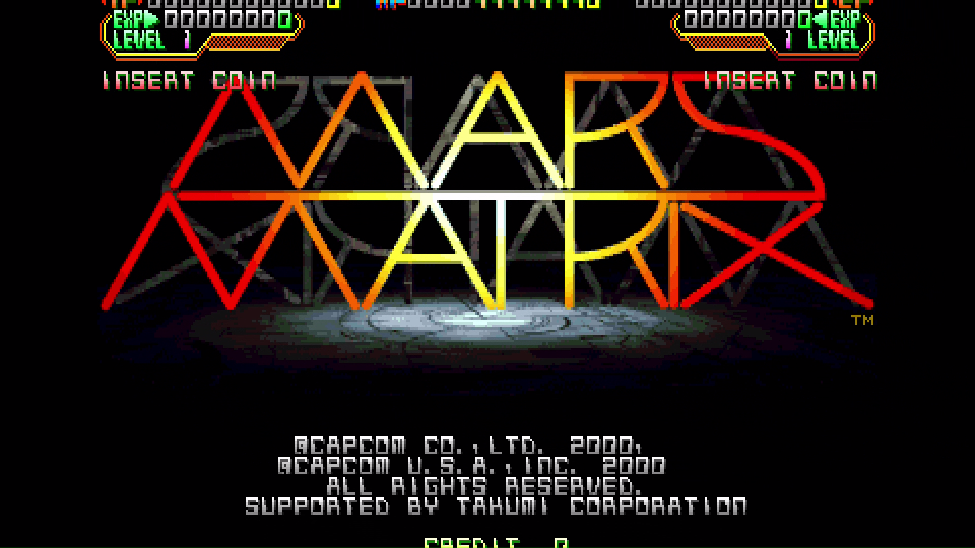
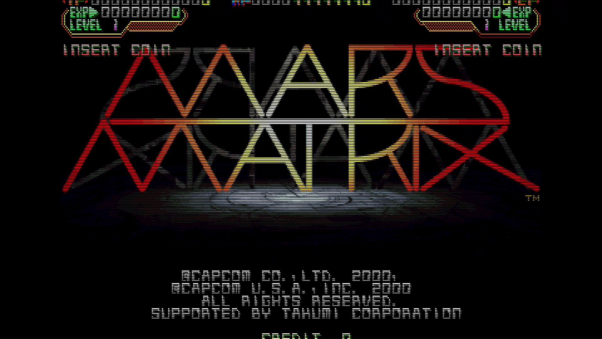
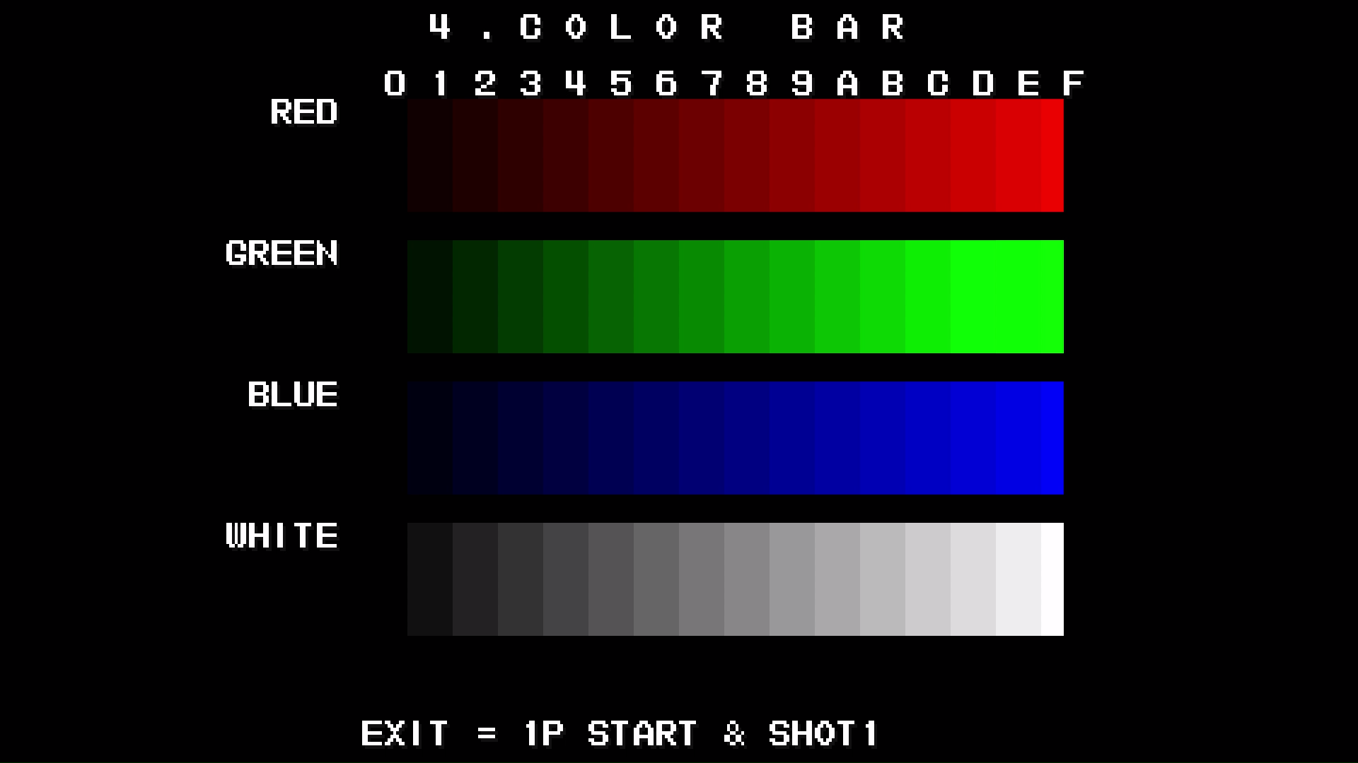
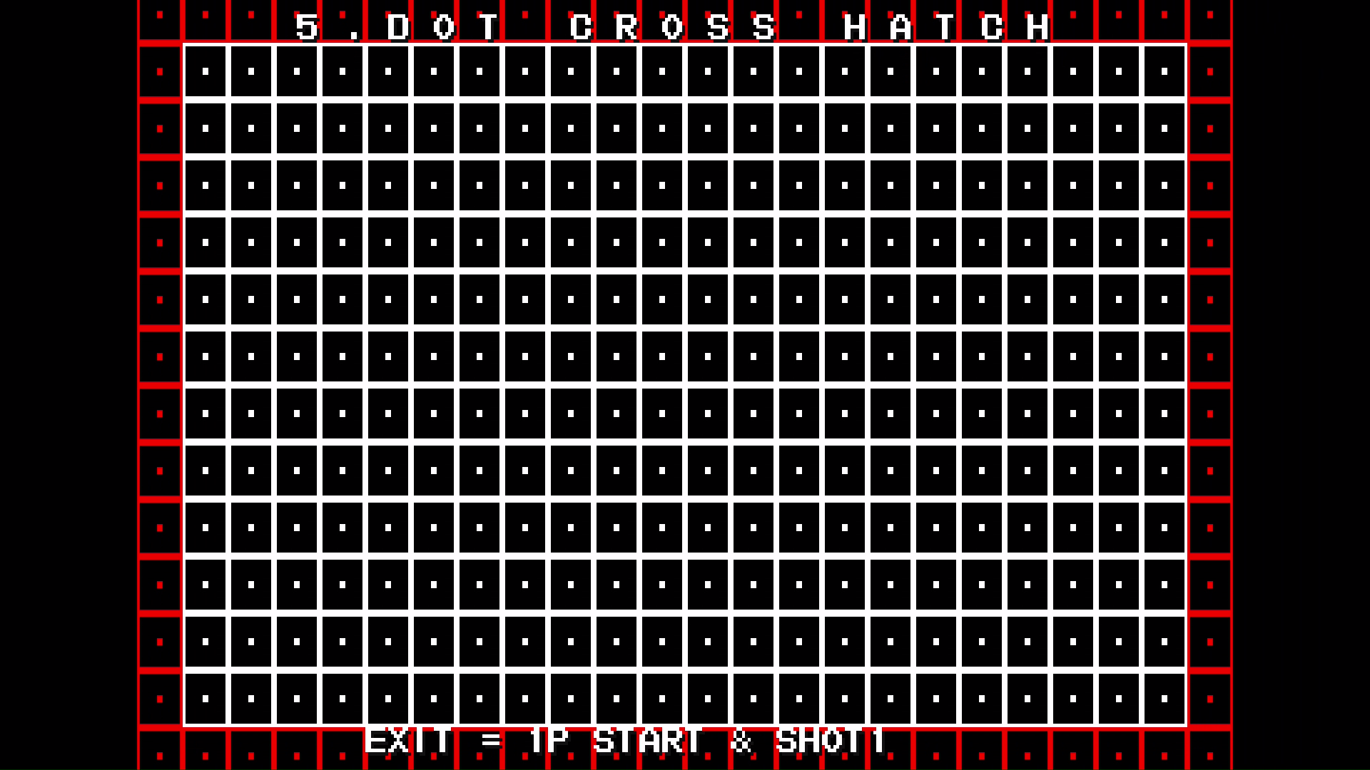
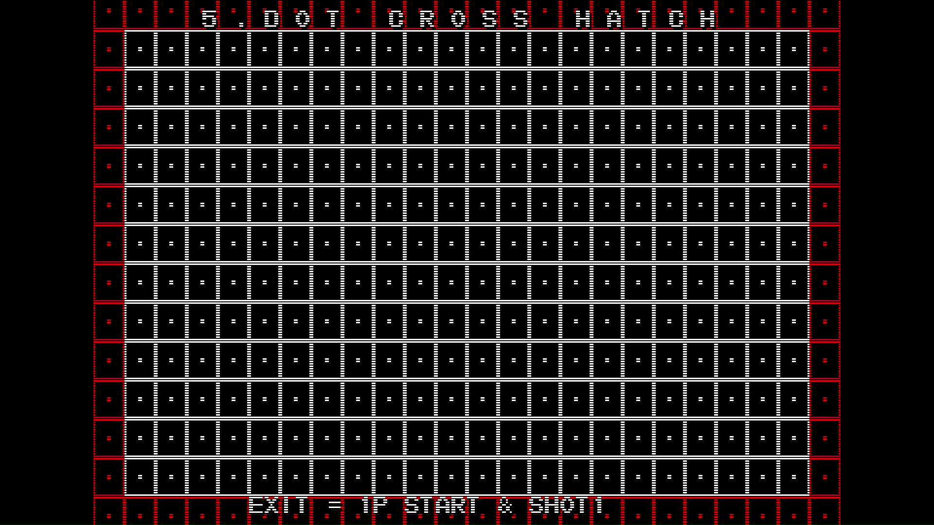
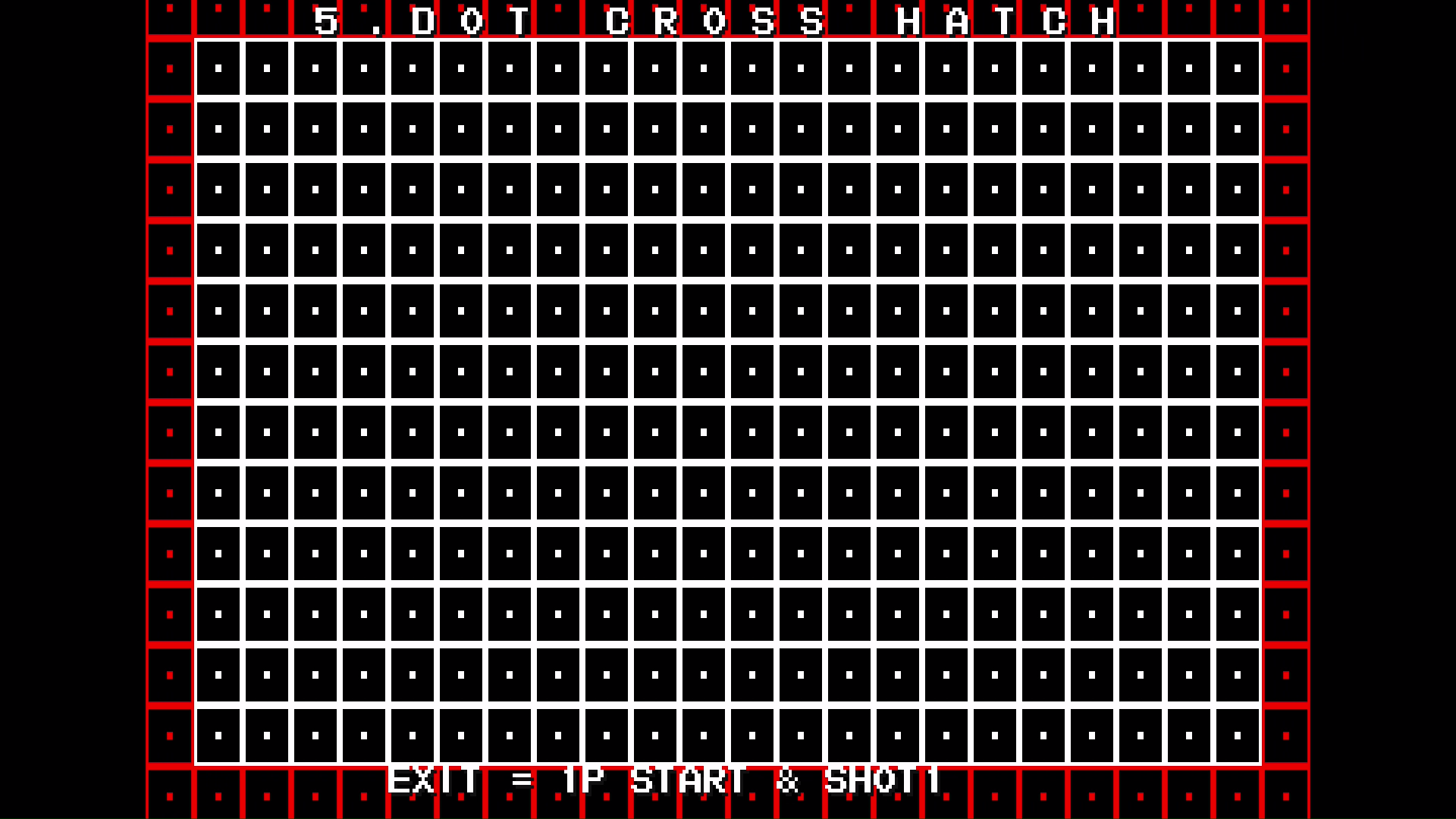
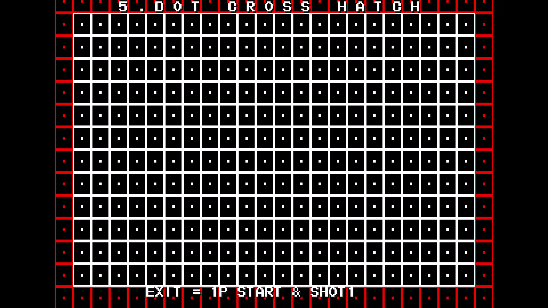
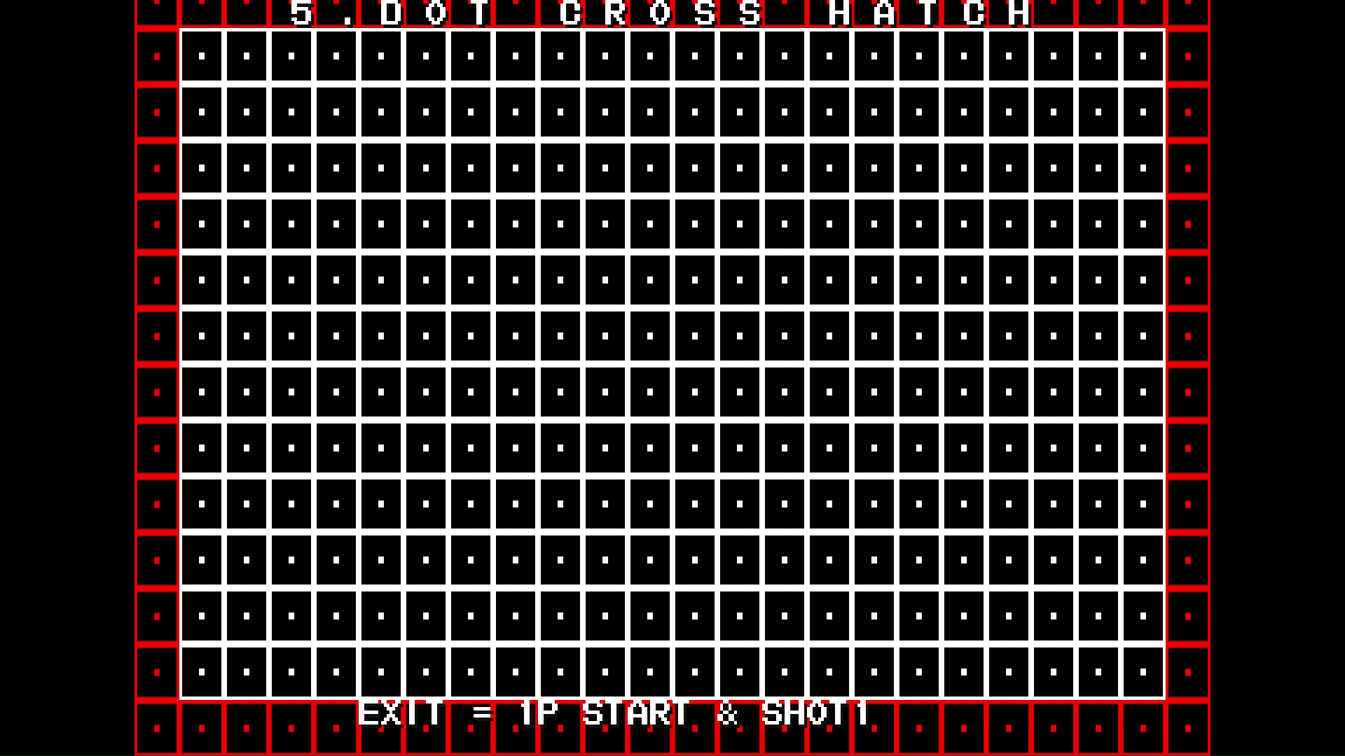
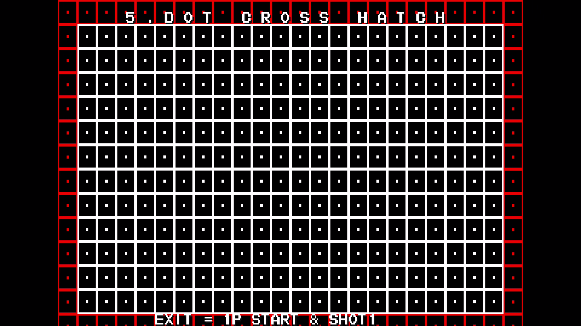
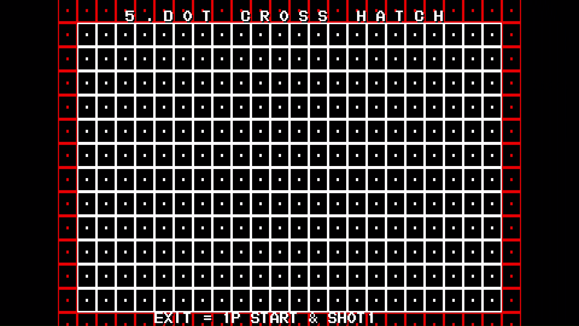
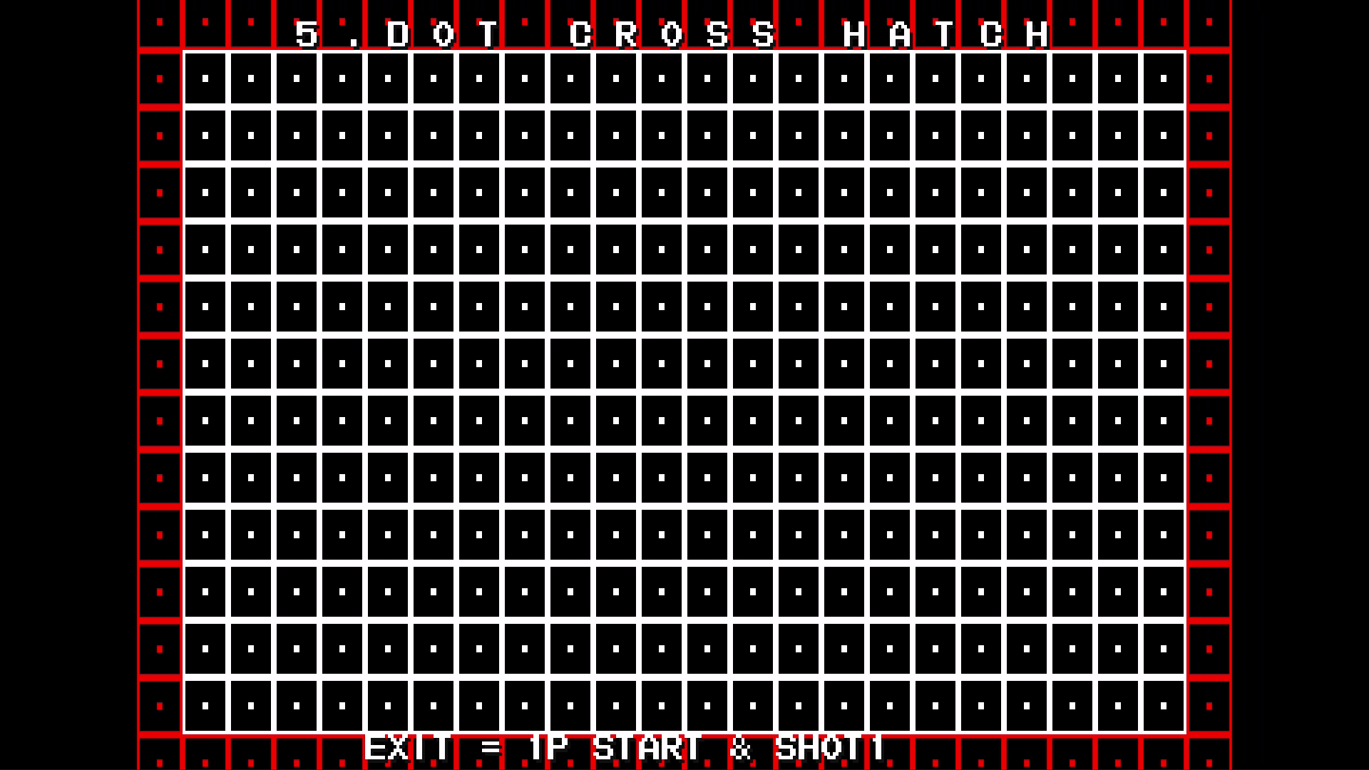
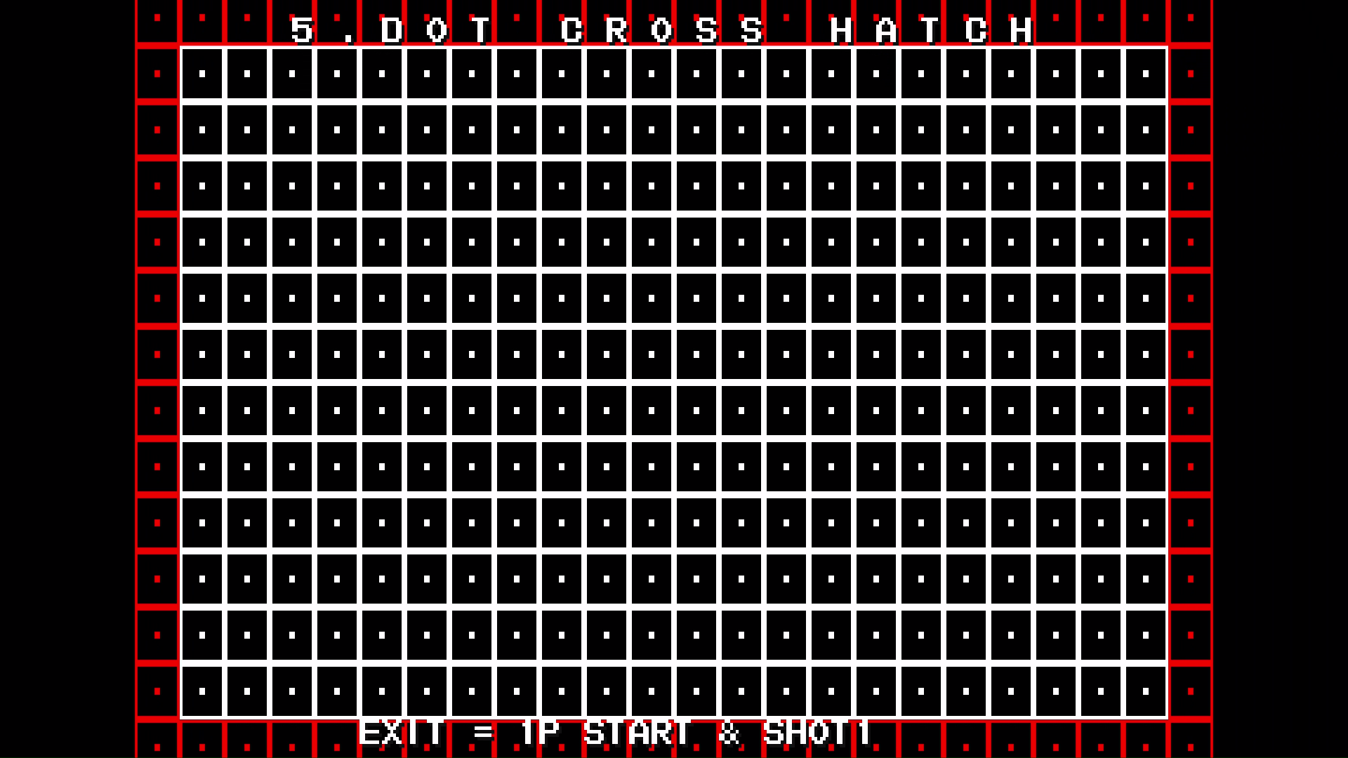
And now for some captured images from the CPS2 digital AV interface. There won’t be any captures from the OSSC Line5x mode output for comparison because my video grabber doesn’t like it, unfortunately.


You’re using this exclusively for play through the HDMI port, correct? Do you know wether adding the digital AV interface affects the signal through the normal Jamma connector?
This looks like a cleaner solution than a chain of Jamma ->Scart -> HDMI adapters and would be a greta way to run captures from my Darksofted VS Blast.
Yes, I’m using it exclusively for playing through HDMI. JAMMA output still works though and you can run them side by side for comparison.