
The other day I prepared my Atari Jaguar to build a rotary controller for Tempest 2000. I hadn’t used it in a while and accidentally picked the wrong power supply – smoke was rising from the console immediately.
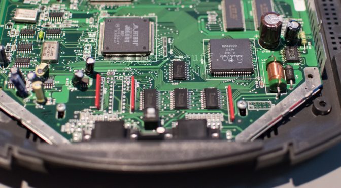
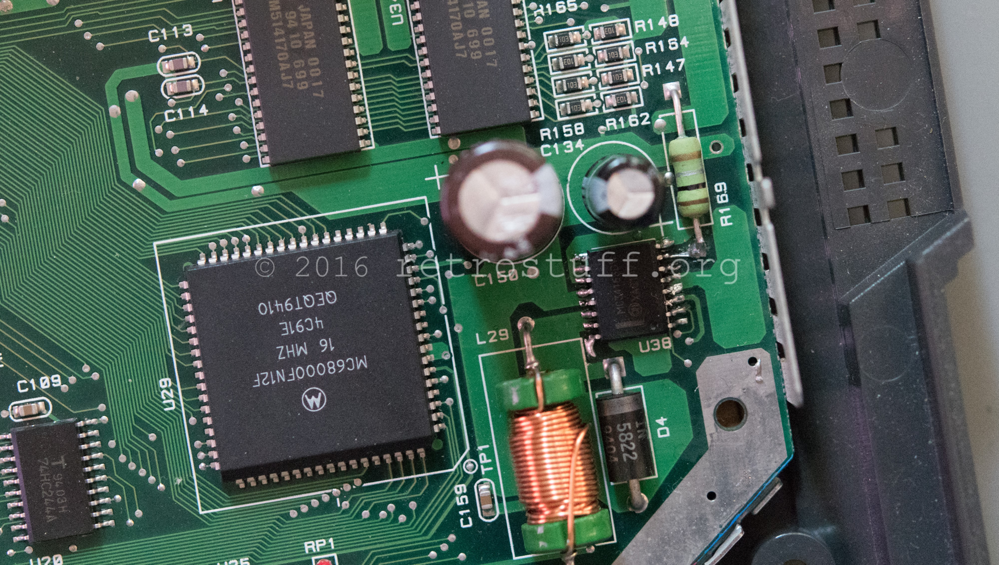
The culprit was easily found, chip U38 (MC34163DW):
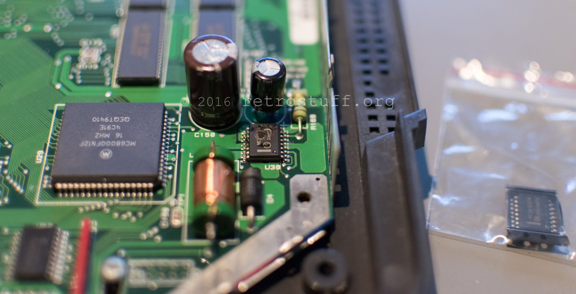
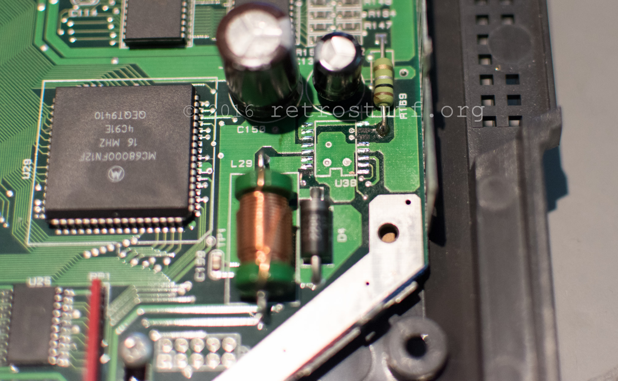
I wasn’t careful enough during the removal and lifted three solder pads with the chip:
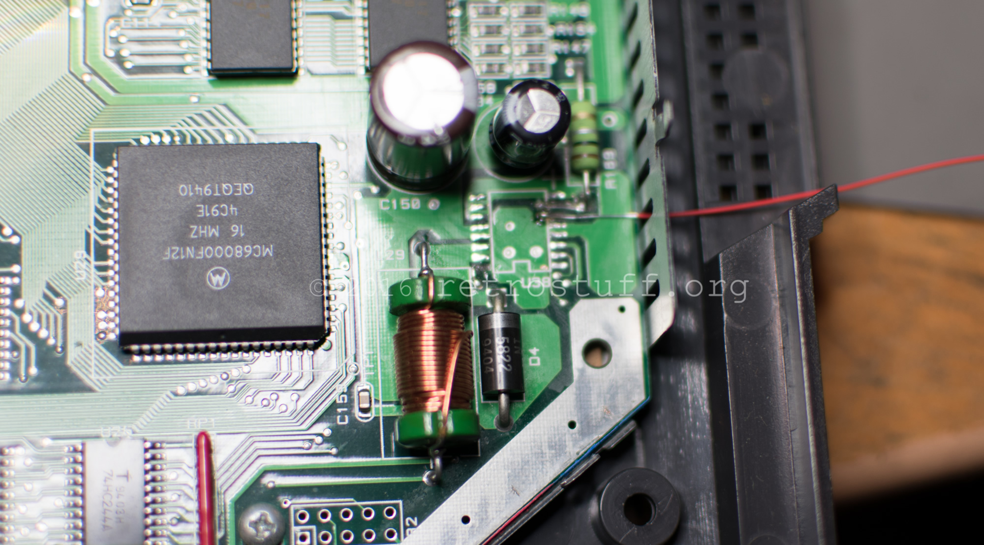
I fixed the upper pads and the trace to the resistor with Kynar wire:
Sound fix
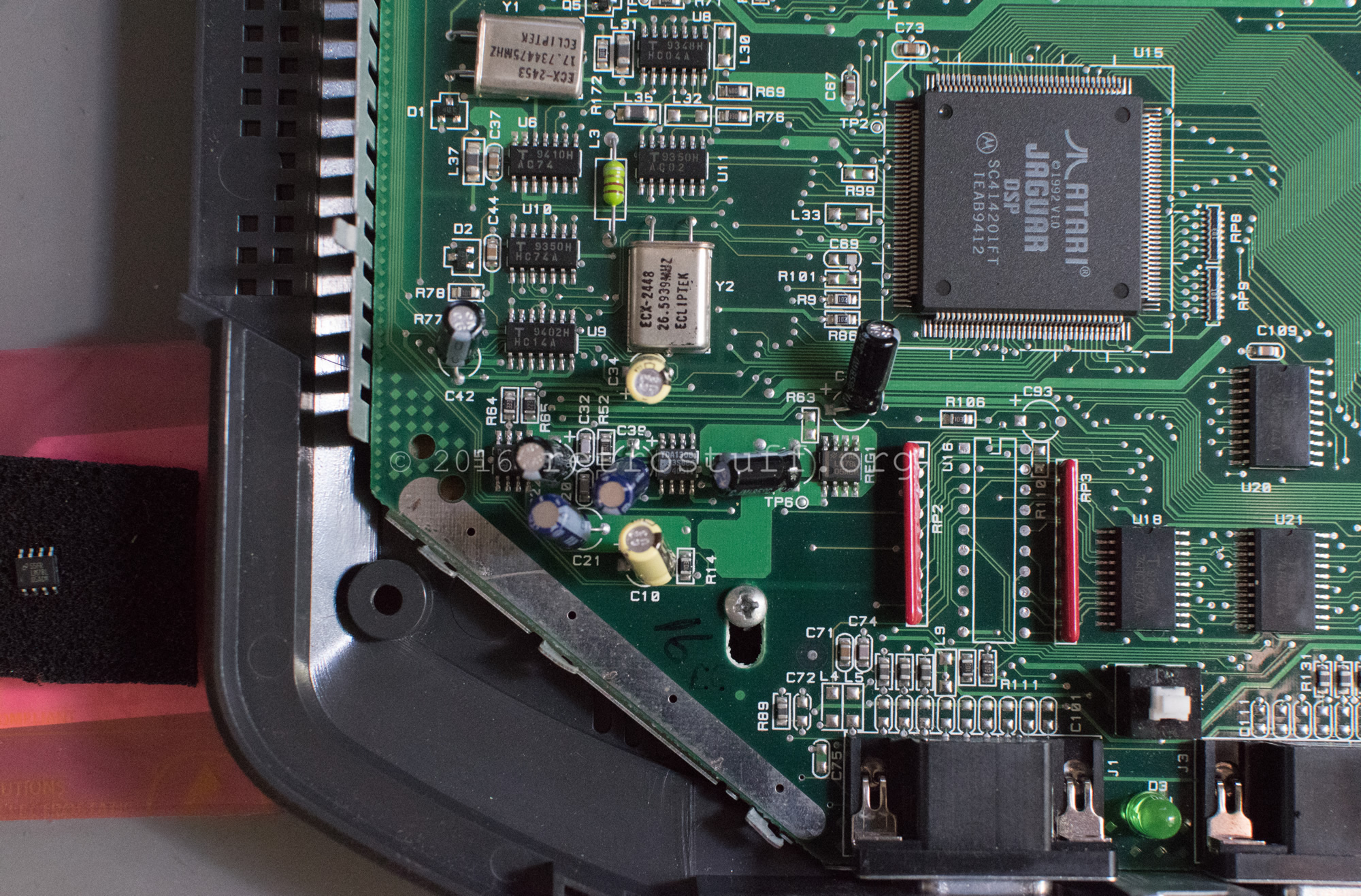
The power problem was fixed, but there was no sound in the games. It seems that this is a common issue as there is no fuse protecting the power regulators. Fixes are being discussed here and here. The capacitor C134 was fine and didn’t need to be replaced, so I focused on the regulator REG1.
No accidents happened this time:
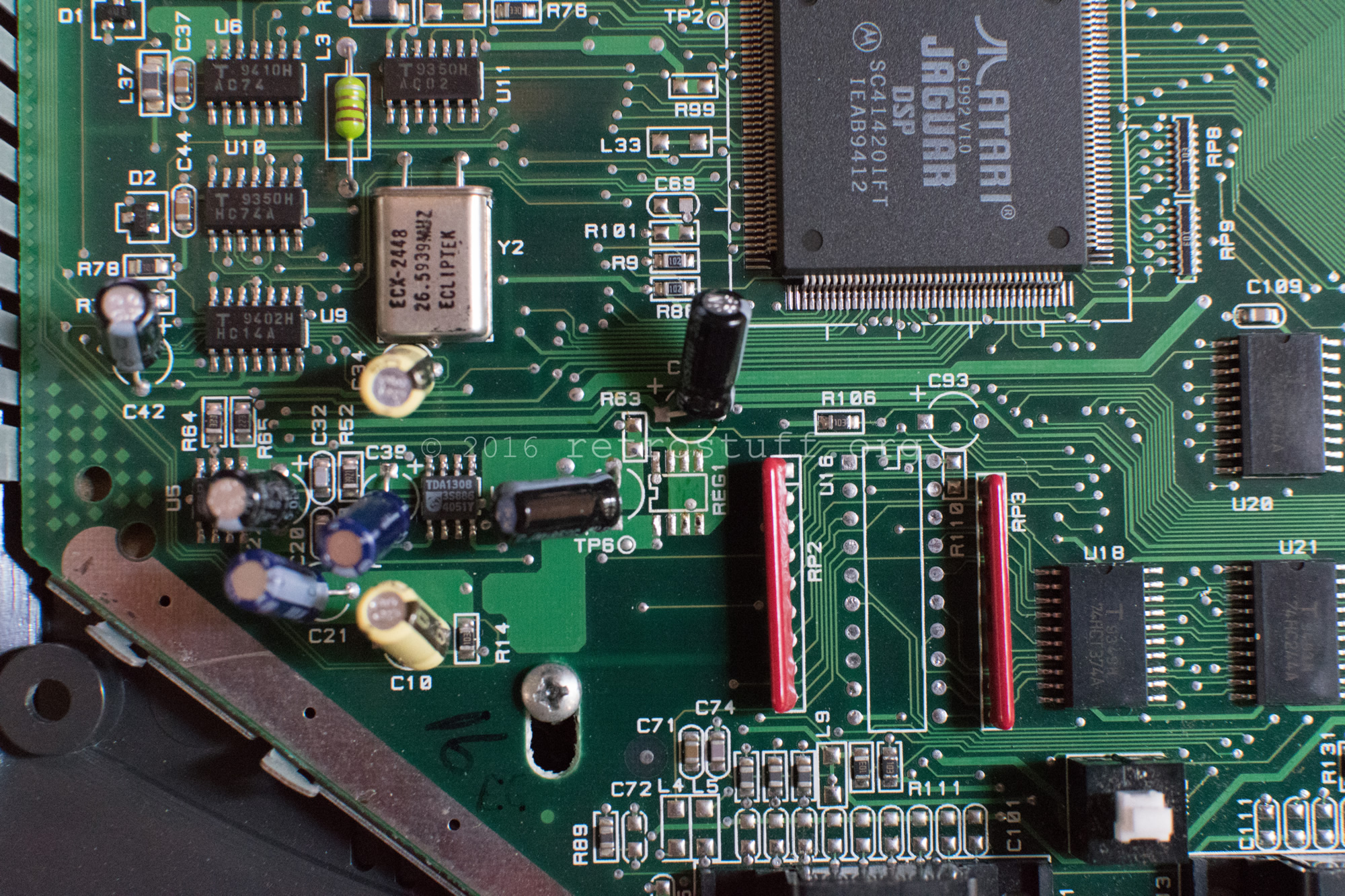
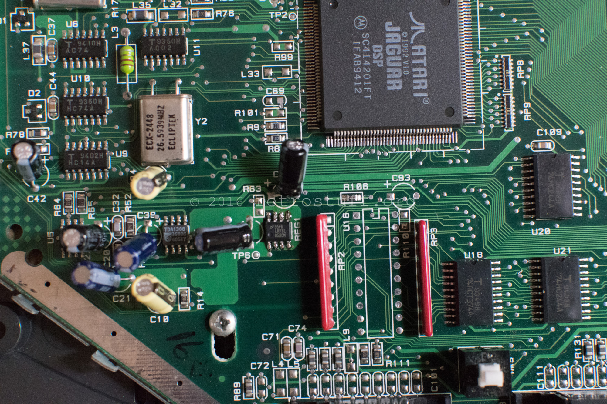
Done! Tempest 2000 is running fine again with sound.
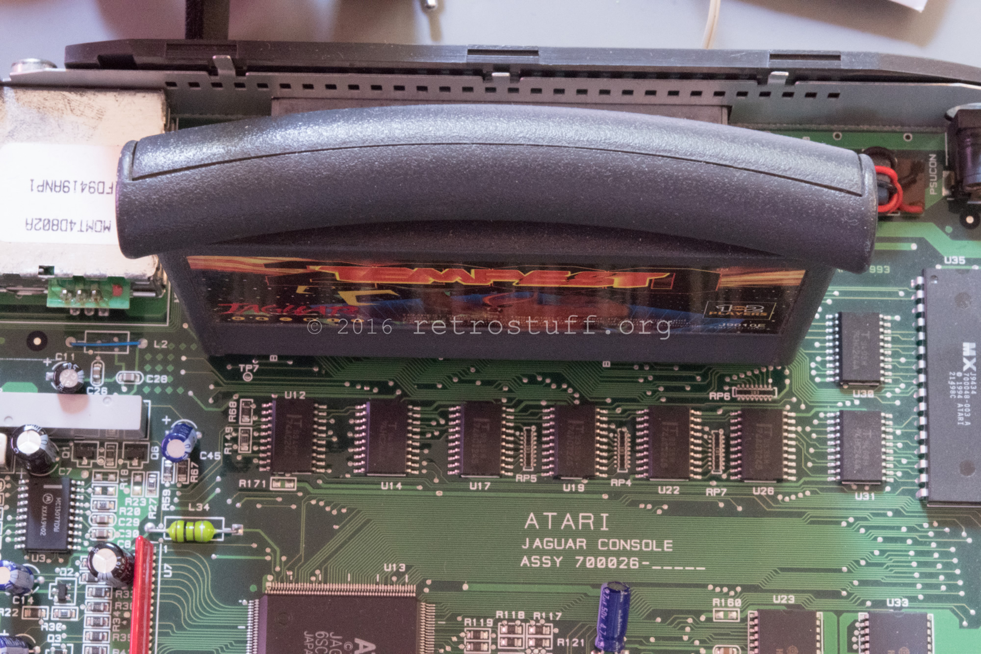
Rotary controller
My rotary controller is loosely based on this tutorial. For the first tests, I used an Atari 2600 Driving Controller as encoder. It only has 4 or 8 PPR (pulses per revolution) and isn’t fun to play with as it moves the object way too slow.
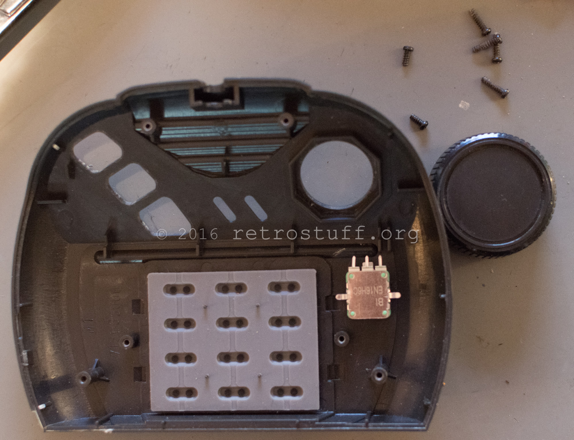
A better option is a 24 PPR Encoder, e.g. EN16. I went for the configuration EN16-H22AF15 with detents, i.e. it ‘clicks’ on every pulse. The knob of the Atari Driving Controller fits on the plastic shaft:
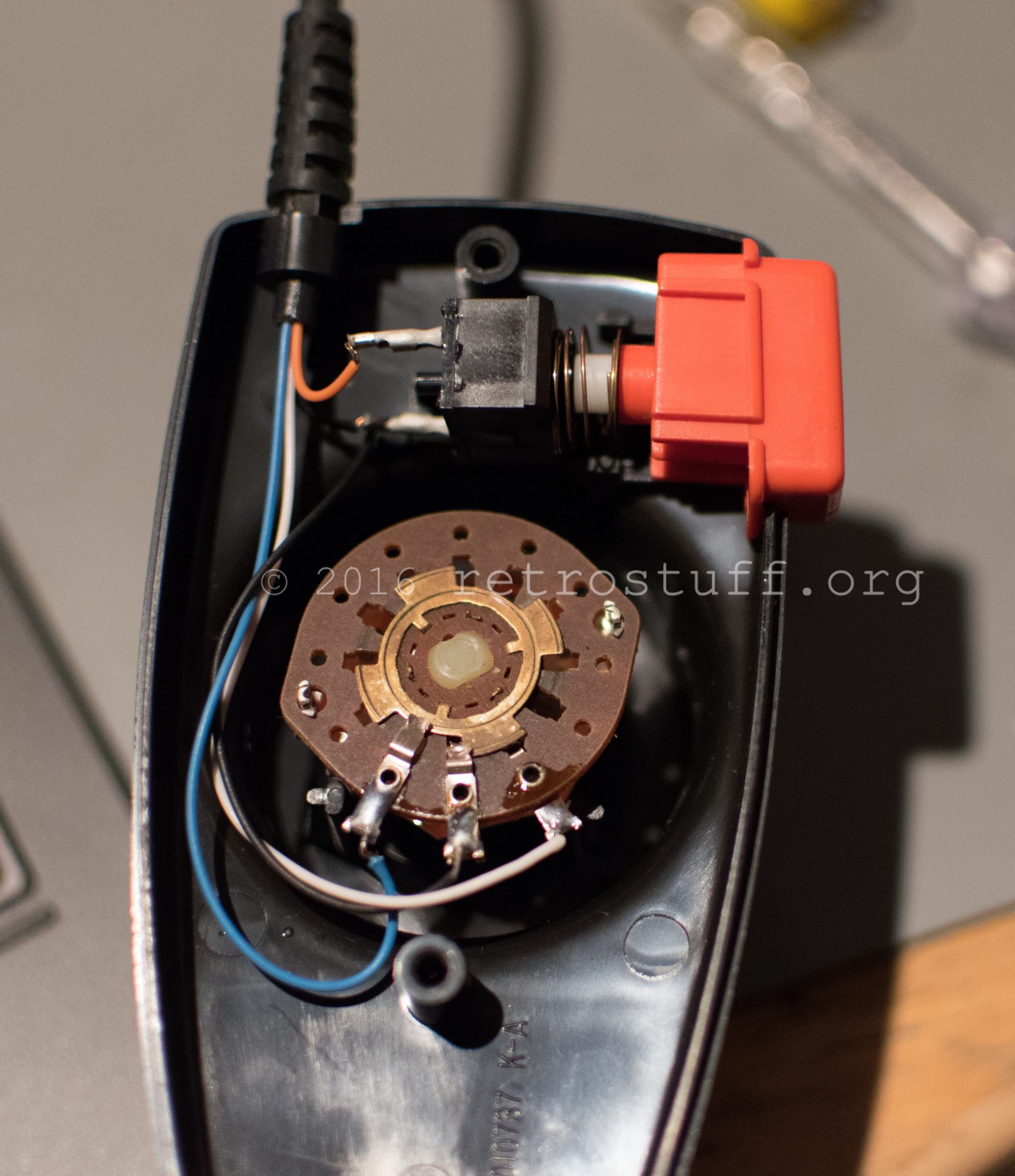
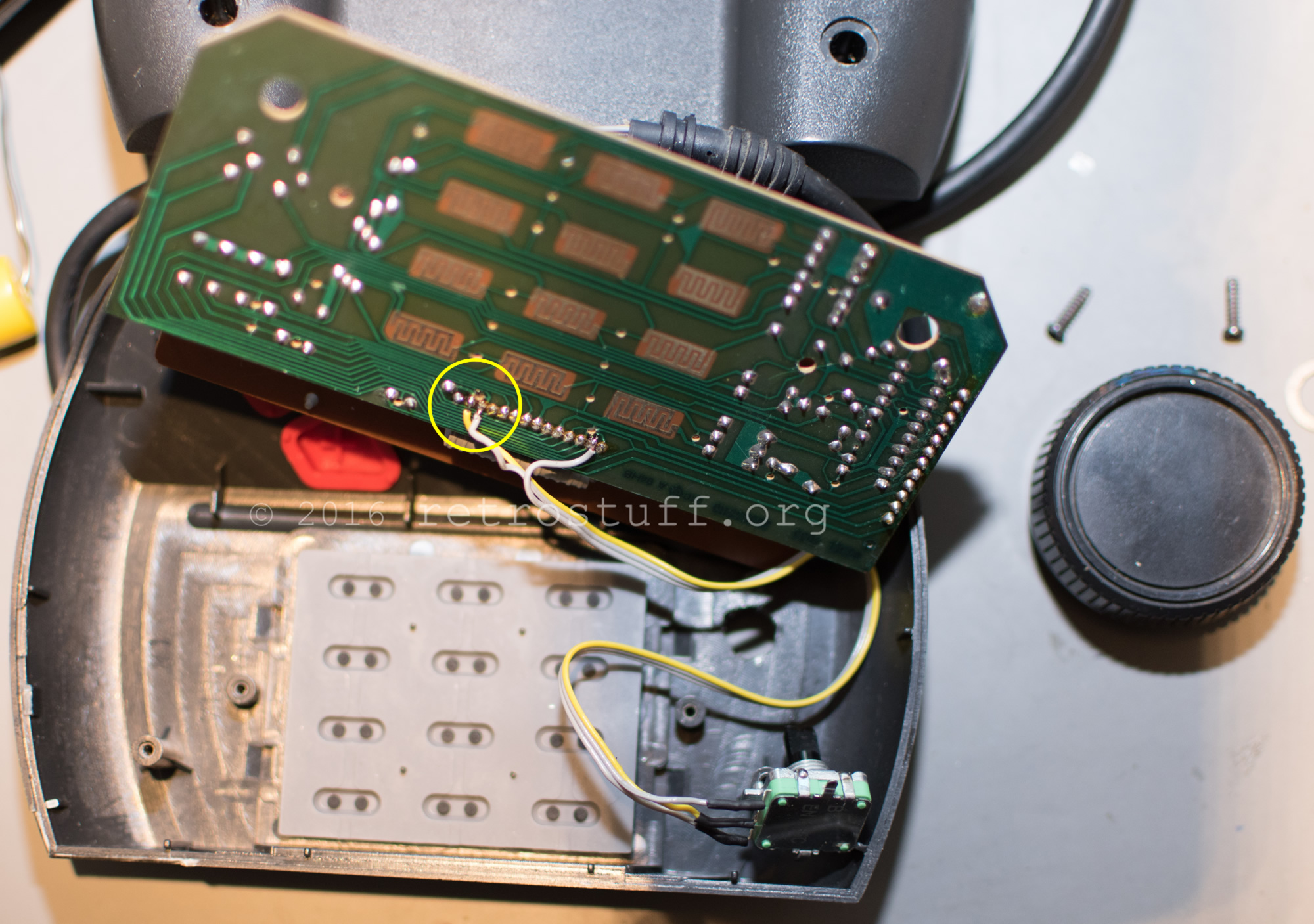
Be careful to solder the wires to the correct contacts of the ribbon cable (yellow circle). There are at least two different PCB layouts:
I just pulled my U38 and pulled a bottom pad on the right hand side.
How can I replace the pad like you did? You ran kynar wire from the missing pad area to the resistor at the top of the chip?
I would truly appreciate your help!
Which pad did you pull? Only pad #7 must be connected to the resistor (and the via hole next to it).
If you’re looking at the board from the front, I pulled the pad on the right hand side, two up from the lettering “U38”.
I see what you mean. That trace to ran to the resistor was for that exact trace. The one I pulled appears to continue on to the bottom of the board to a small capacitor.
Pad #3 is connected to the right via hole, just solder some Kynar wire directly onto the hole.
Unfortunately for me, I just tried to do this again and ended up pulling the pad next to it.
It’s clear to me that I need to work on my skills before attempting this again.
I’m a little disappointed that I did more bad than good the second time around. Thank you for your article and responses to my comments. I appreciate it!