
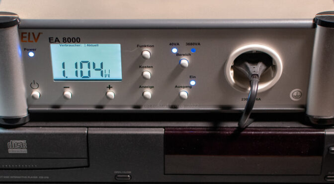
When looking for an affordable and reasonably accurate device to measure the (standby) power consumption of old power supplies, I came across the ELV EA 8000 Energy Analyzer. It’s being sold as complete device or as a kit; I went for the kit to spend some time with it and have a better look inside.
It has two power measuring ranges (40 and 3680 VA), several measuring functions (e.g., active / reactive / complex power, power factor, costs), storage space for 10 devices and up to three different electricity tariffs. Before buying, I was already aware that it has some flaws, but more about that after the assembly.
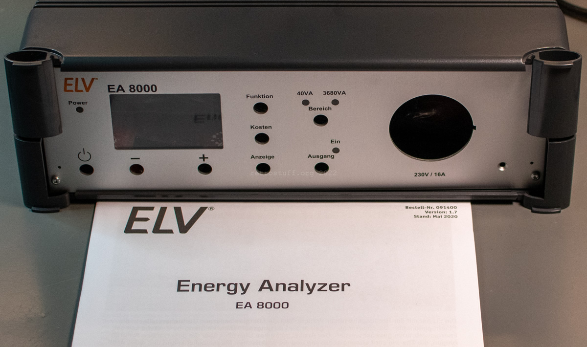
Unpacking
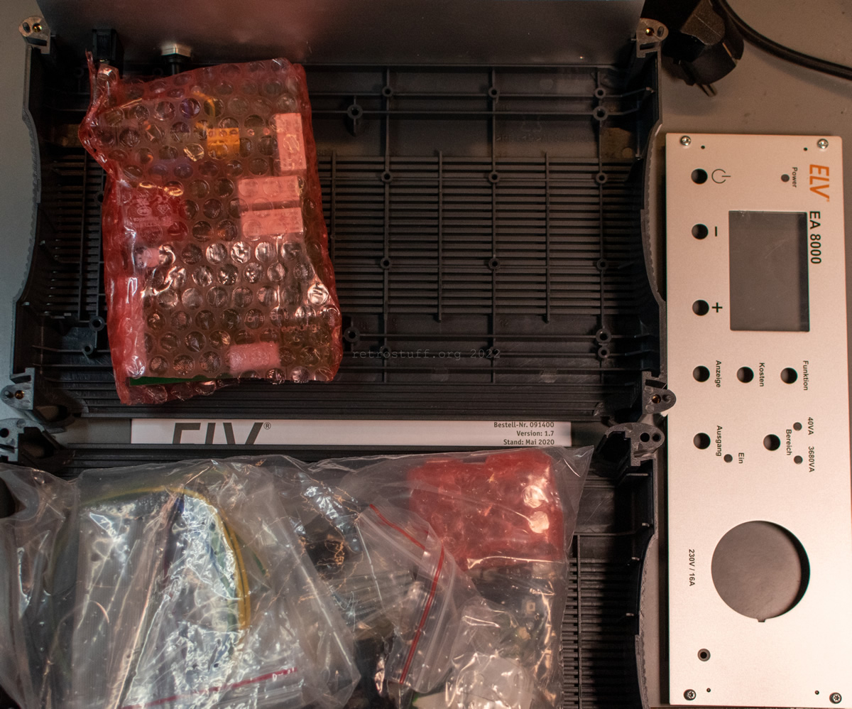
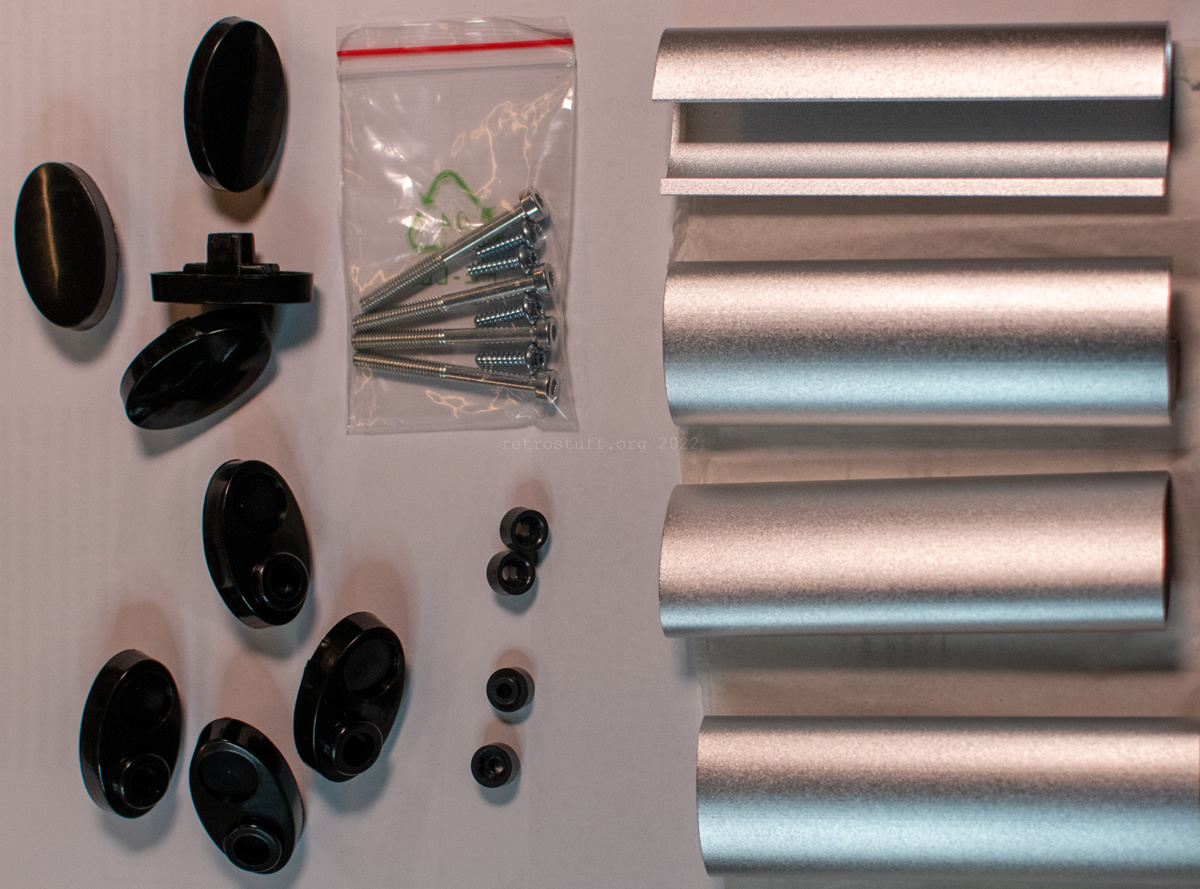
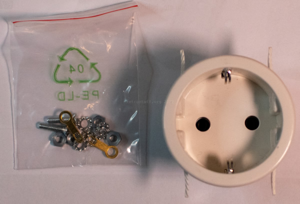
Inside the case I found all necessary parts:
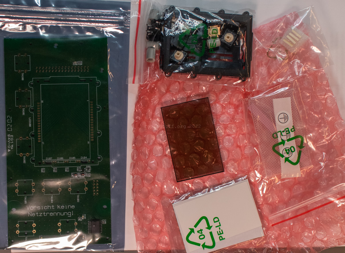
Detailed view of the parts: (I didn’t unpack the various films of the display yet to keep dust and fingerprints out.)

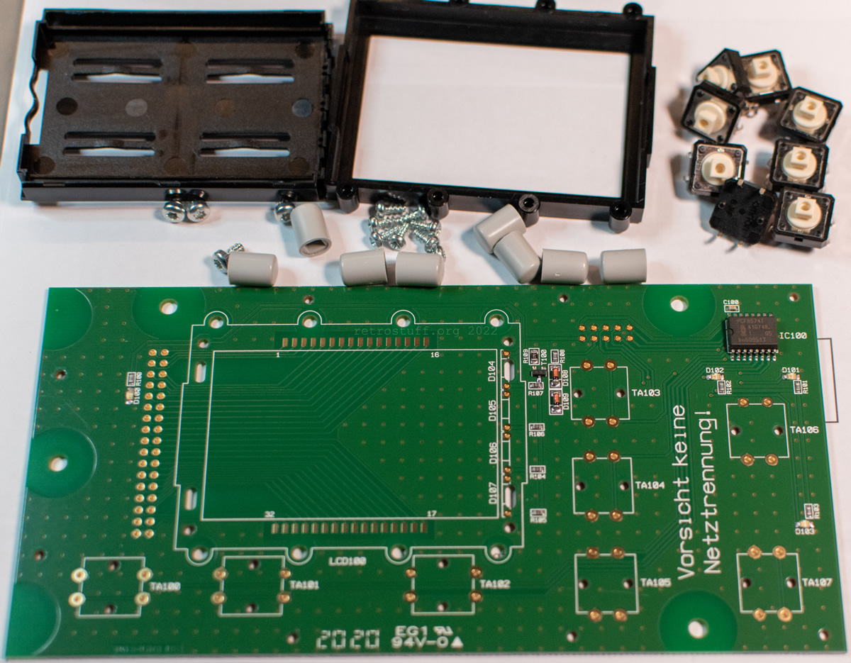

And as a surprise, the base PCB was already assembled:
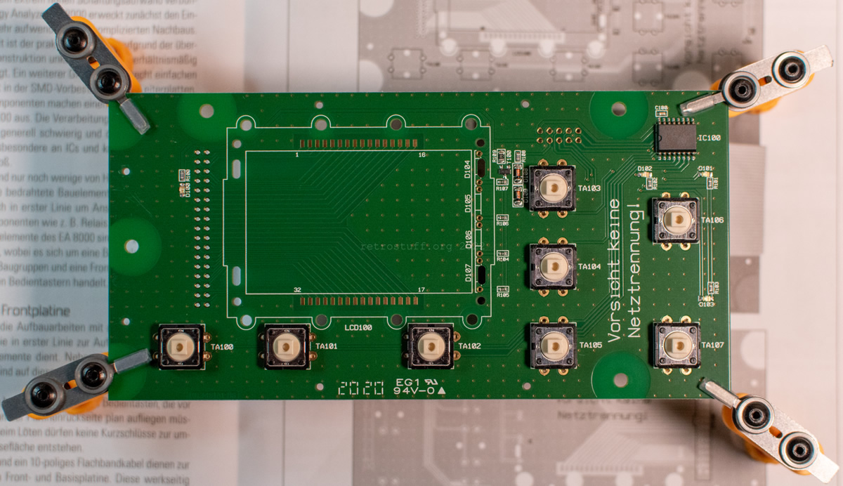
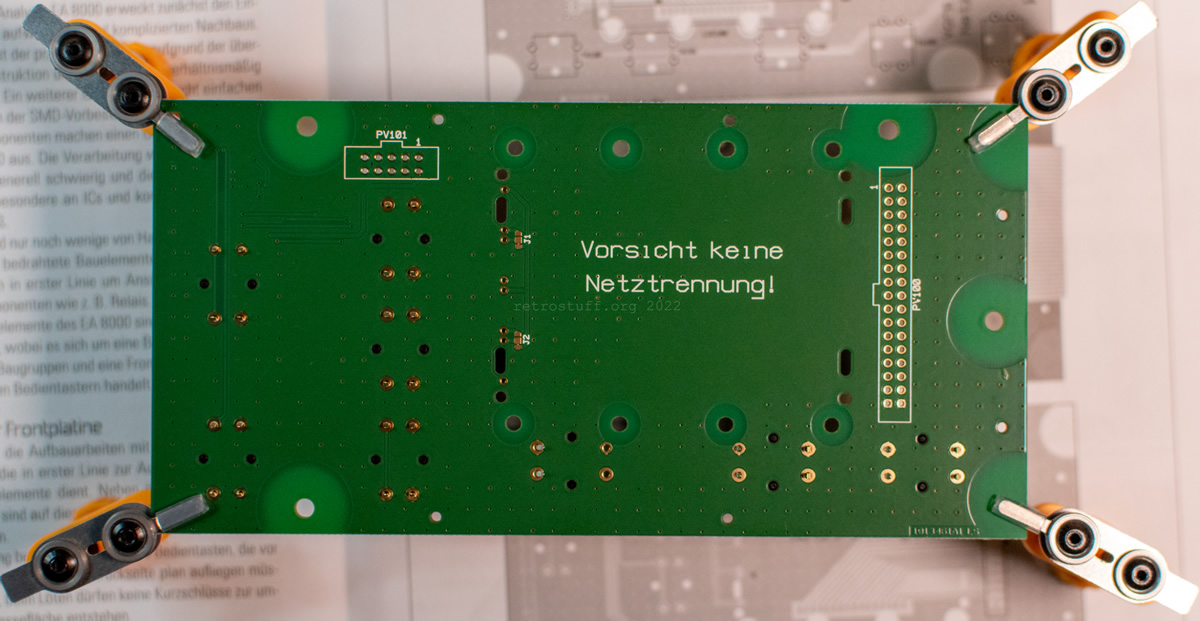
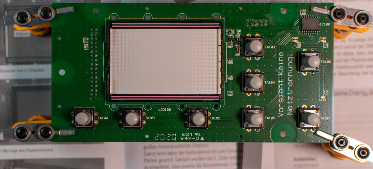
Assembly of the front PCB
A couple of SMD components were already on the PCB, including IC100 (NXP PCF8574T Remote 8-bit I/O expander for I2C-bus with interrupt). ELV recommends to use lead-free solder for the missing components.
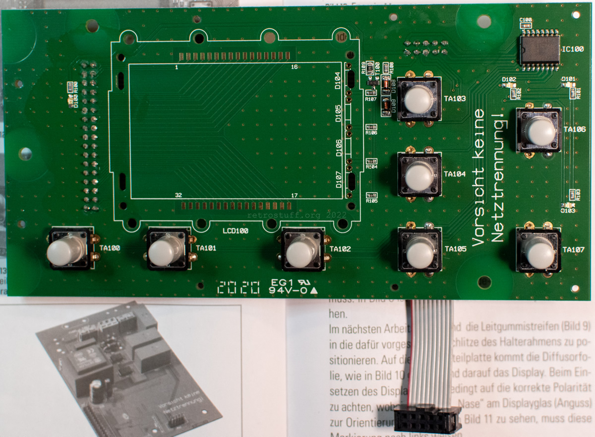
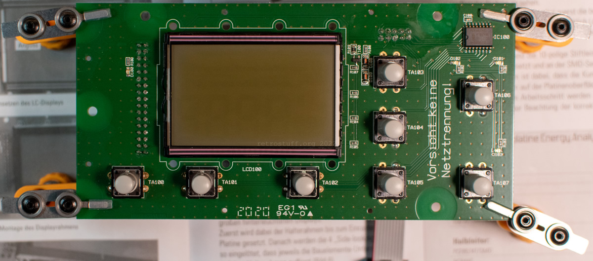
First, installation of the buttons, ribbon cables and button caps:


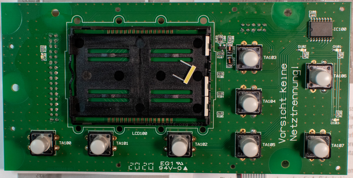
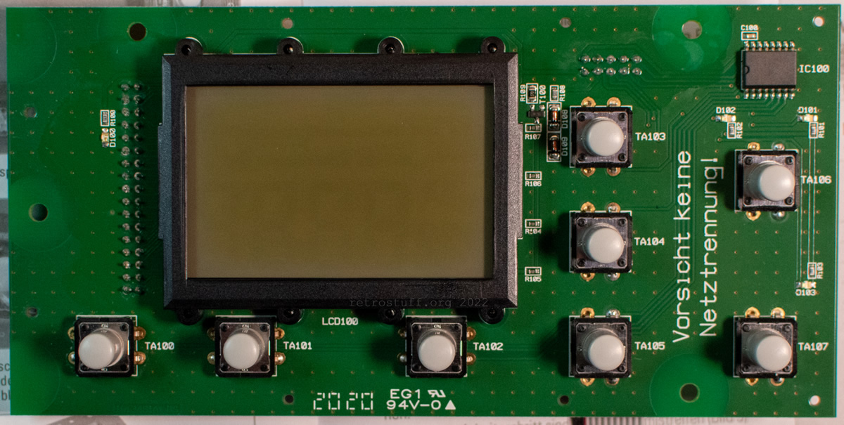
Next, installation of the display: Frames, backlight, various films (only 2 out of 4 are shown in the pictures), conductive rubber and LCD.

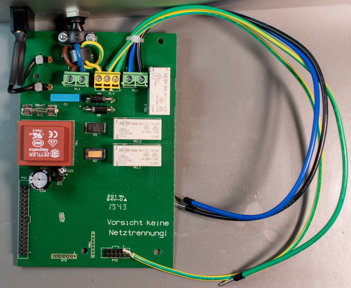
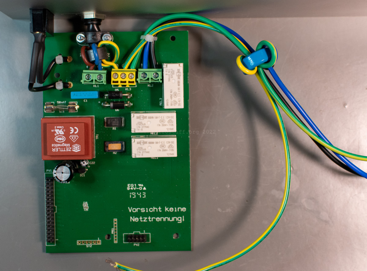
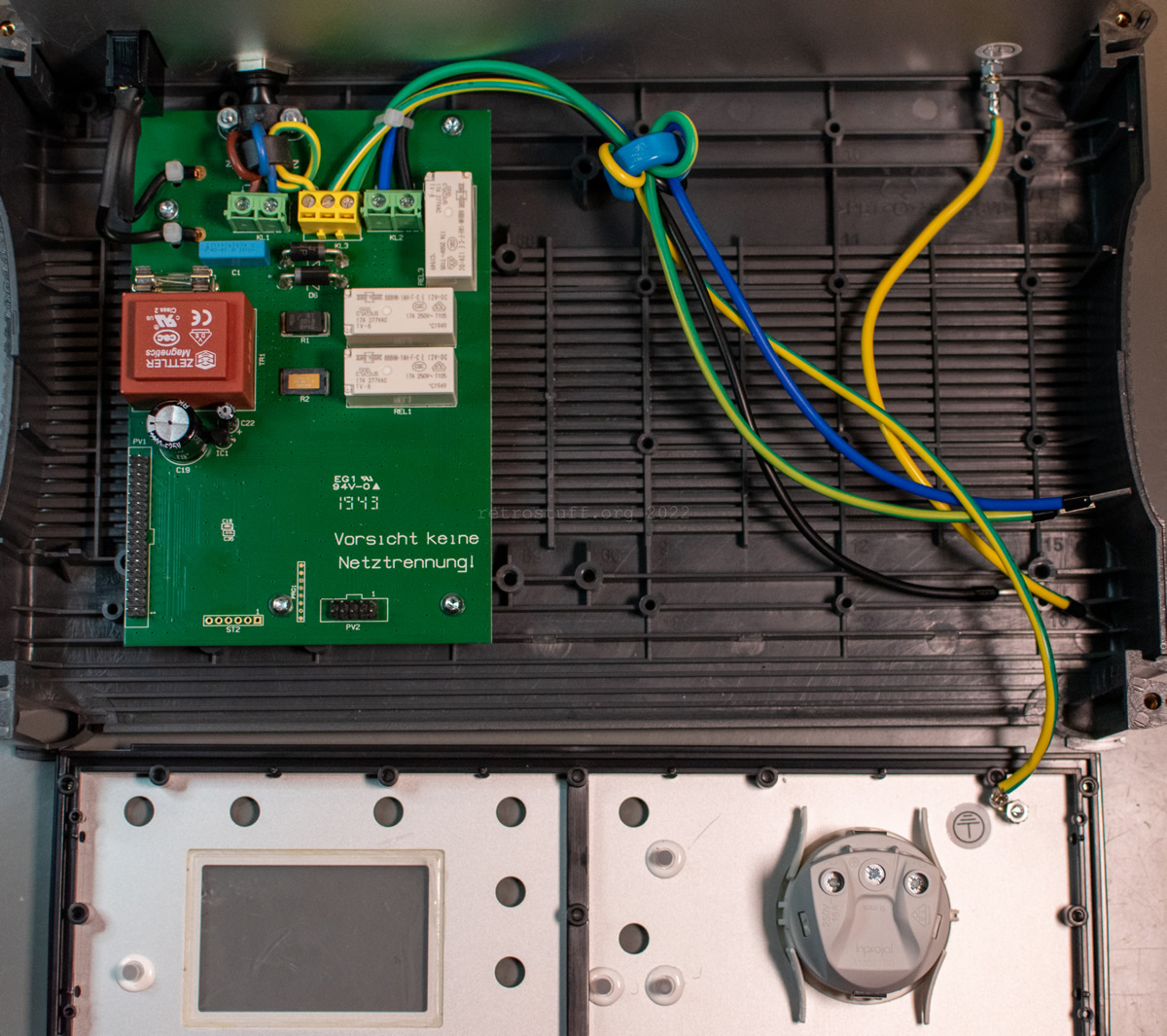
Base PCB and wiring
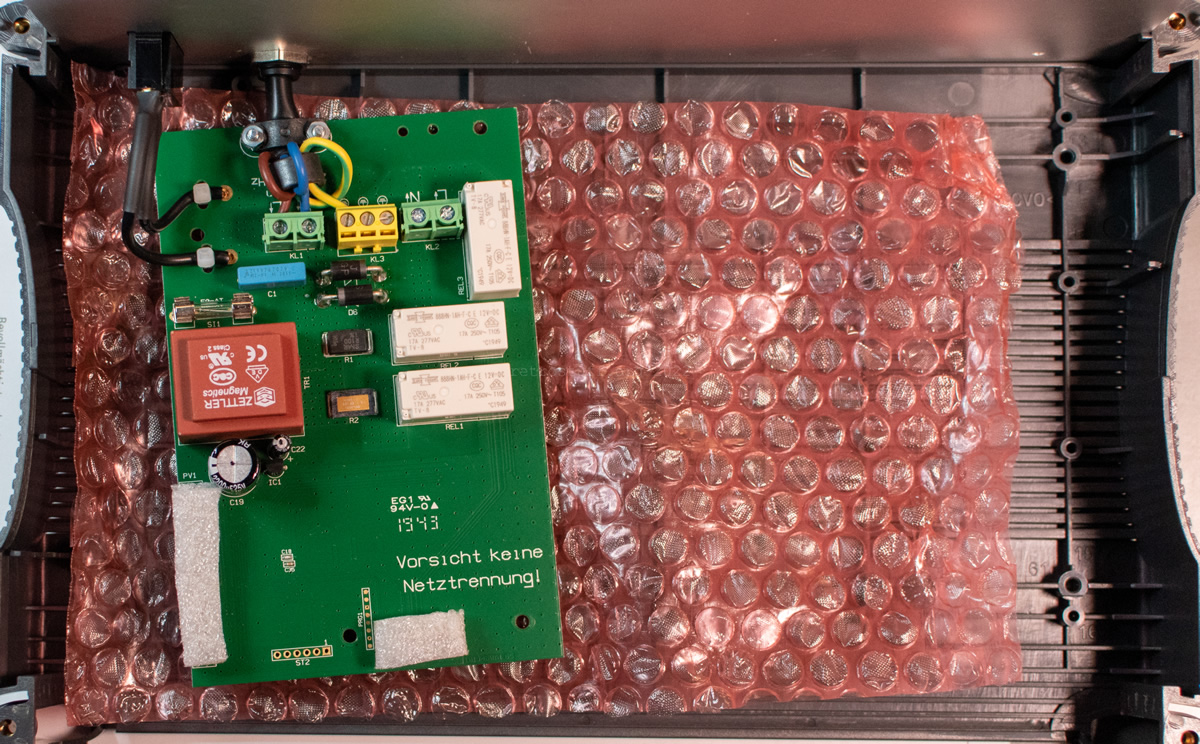
Close-up of the base PCB. It was already assembled and wired to the back cover. The controller is IC2 (Teridian 71M6521FE Energy Meter IC) and data is saved in IC4 (Cypress FM24CL64B-G 64-Kbit (8K × 8) Serial (I2C) F-RAM).
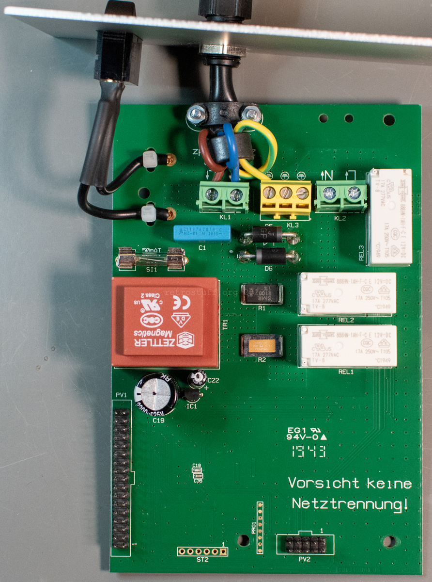

Before I started wiring, I noticed that the PCB wouldn’t fit in the case because the power cable was too long. I had to loosen the screw and pull it out a bit. Then, I prepared the conductors that go to the front panel. There are three slightly different earth conductors, but I eventually figured out which one goes where.
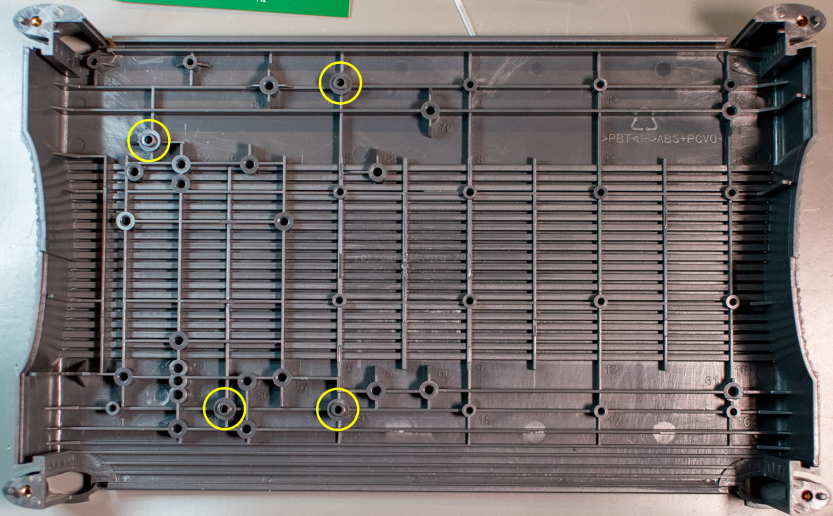
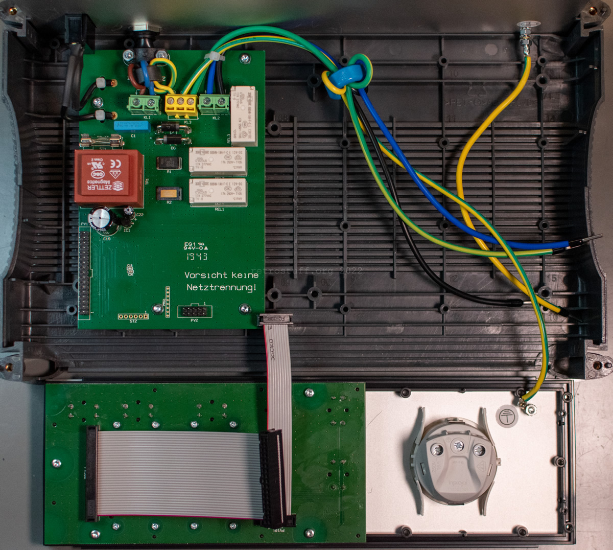
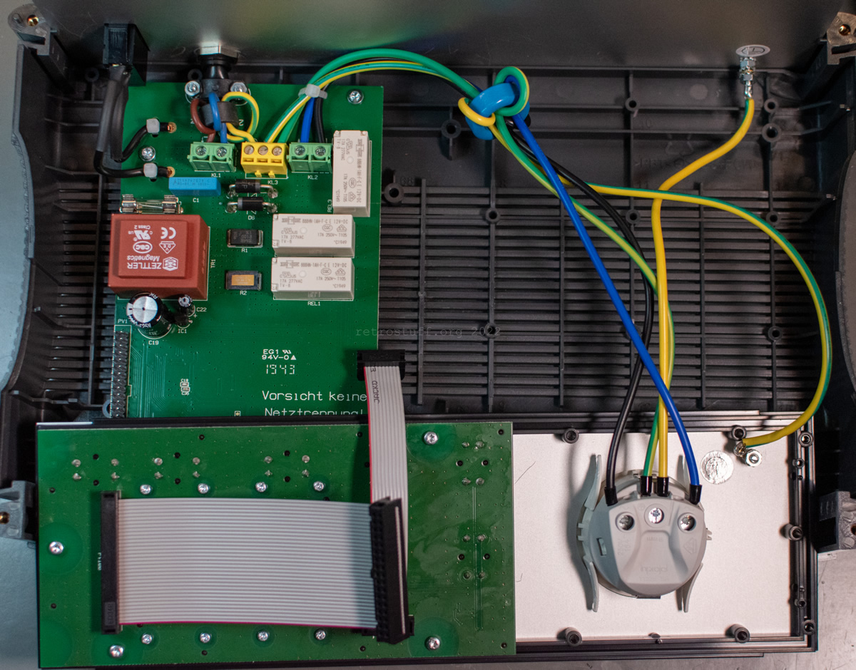
Preparation of the case. Note the positions of the plastic domes that need to be placed before mounting the base PCB:
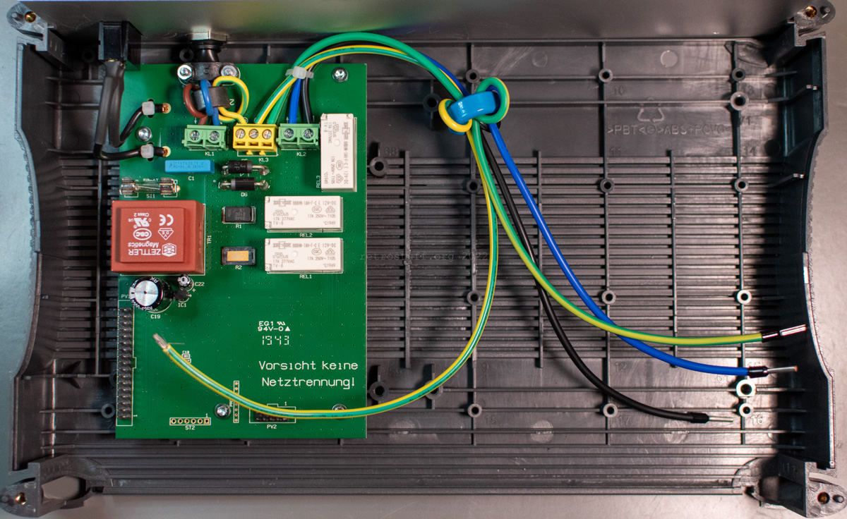
Assembly of the front panel (socket, display PCB), more wiring and tidying up. In the end, only half of the space is used. All of this could have been placed more efficiently in a smaller case.
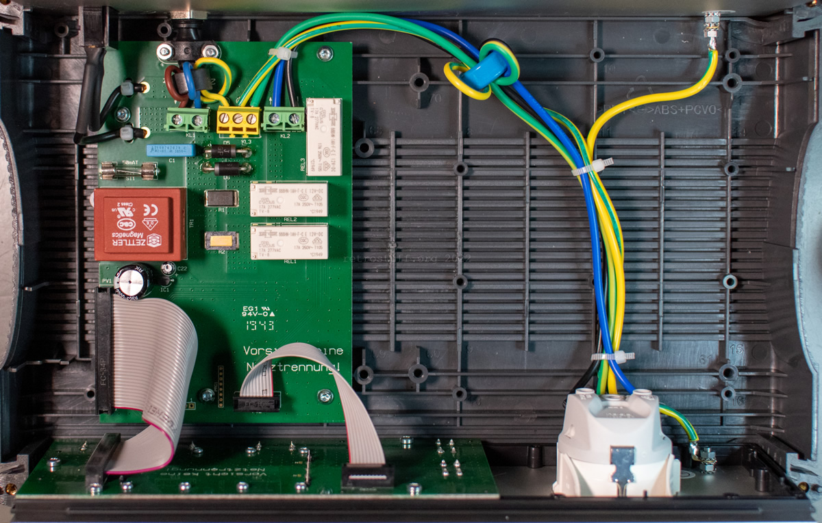
A couple of boring photos of the case assembly and placement of the feet.


Room for improvements
As mentioned above, the EA 8000 Energy Analyzer has some flaws and noticeable problems that are described here (in German). I have yet to figure out if these issues affect the results of the devices that I want to measure. For now, I will use a Schuko adapter with lab/safety sockets from the same manufacturer (ELV MA230) to measure the DC component. Coincidentally, this adapter also has a weak point, as described here (in German): It has no polarity indicator, i.e. whether the phase conductor is connected to the black sockets (or connected at all).
Back to the EA 8000: It also has no indicator for polarity and only a single-pole power switch. This means that depending on the orientation of the power plug, you don’t know if the phase is really on the left and neutral is on the right (the way we wired the Schuko socket before). And what’s worse, the entire base PCB could be live even if the power is switched off. At least, the output socket is always completely switched off.
ELV is aware of this and points out in the manual that the device must not be connected to the mains when the case is open.
There is nothing I can do about the inaccuracy of the measurement except observe it, but I plan to do something about the polarity and safety: A double-pole power switch on the back and a neon glow lamp as phase indicator on the front. There’s also enough room for additional lab/safety sockets to help measure the DC component with external measuring devices.