The CDI660/00 is one of the last professional CD-i players by Philips. The mainboard, Mono IV, is also used in various consumer players. So far, there are no tutorials for 60 Hz modification. When this topic came up in the community on The world of CD-i, I looked it up in the CDI220/80 service manual (also Mono IV, with plenty of remarks for other player models) and attempted the modification myself. It has been on my to-do list for quite some years now.
First, we need full access to mainboard. Remove the marked screw of the DVC plastic holder.
Remove the marked screws on the right side of the back panel as well.
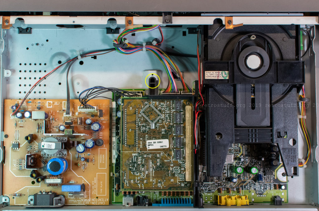
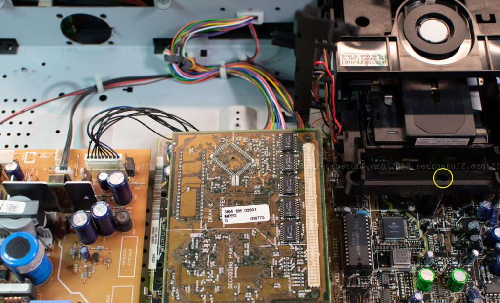
Bend the plastic holder up and take out the DVC. Next, unscrew the three screws that hold the CD loader assembly in place. You will have to pull the tray out to access the screws. I’ve marked the first one in the picture, the other two are inside the two holes in the tray close to the front panel. To take out the CD loader assembly, remove the front bezel first, then push the tray back in and carefully lift the assembly. Underneath are three connectors that need to be unplugged.
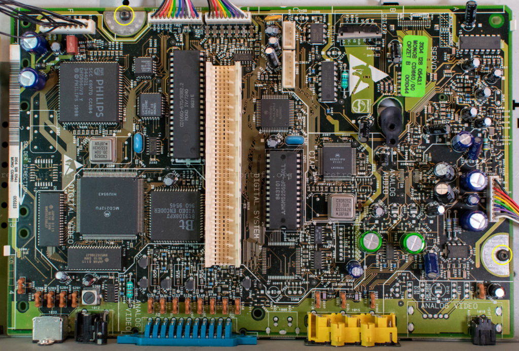
Finally, access to the mainboard. To take it out, unscrew the two screws and unplug all cables.
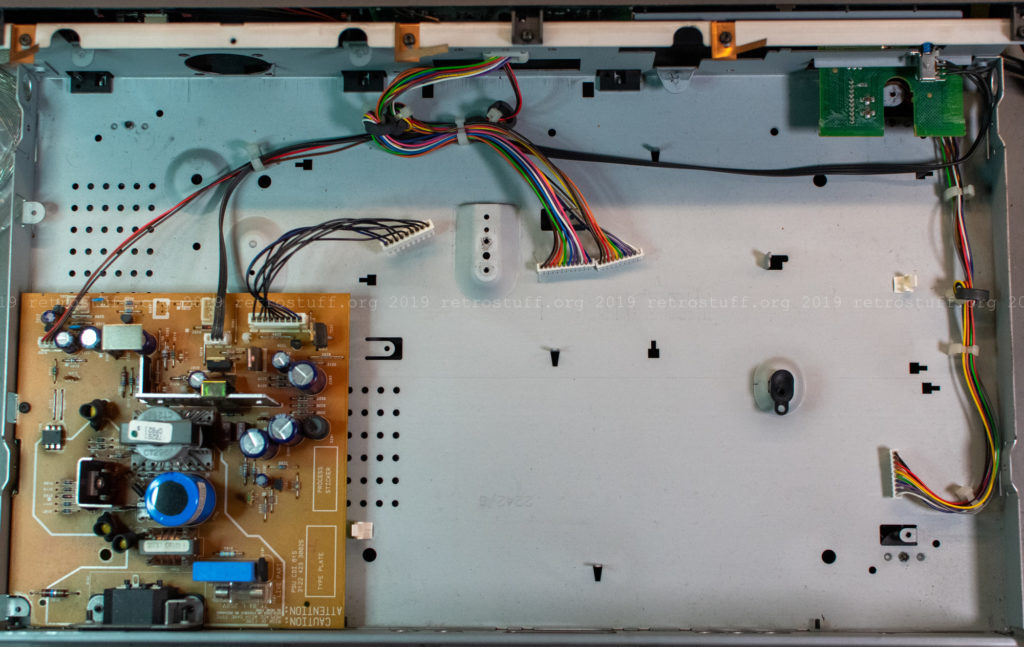
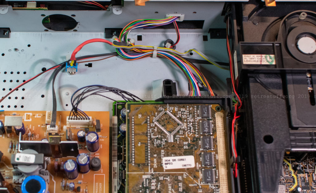
This is what’s left in the CDI660:
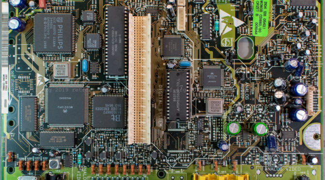
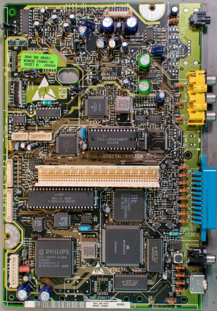
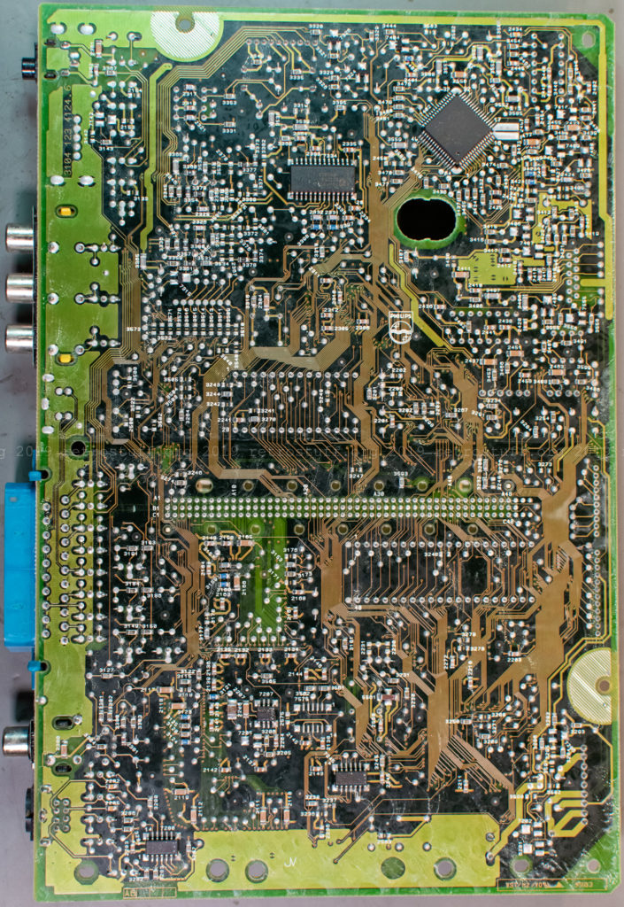
Close-up pictures of the Mono IV board:
Now for a detour about the NVRAM. Skip the following two chapters if you are just here for the 60 Hz modification.
32 KB NVRAM
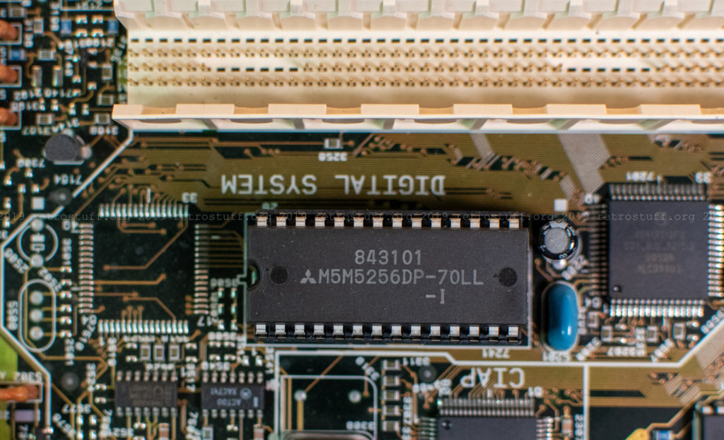
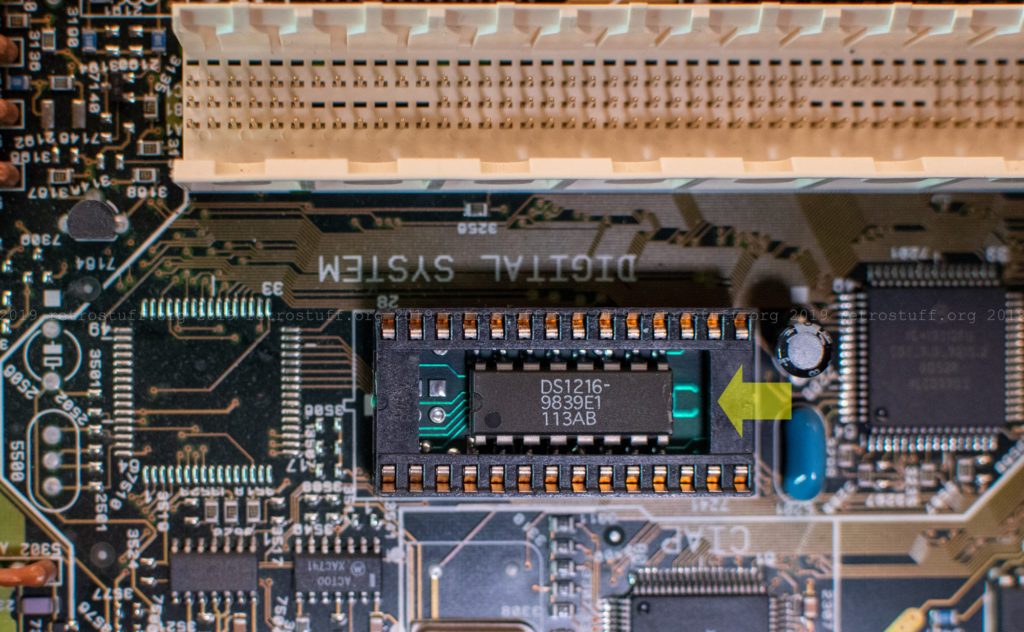
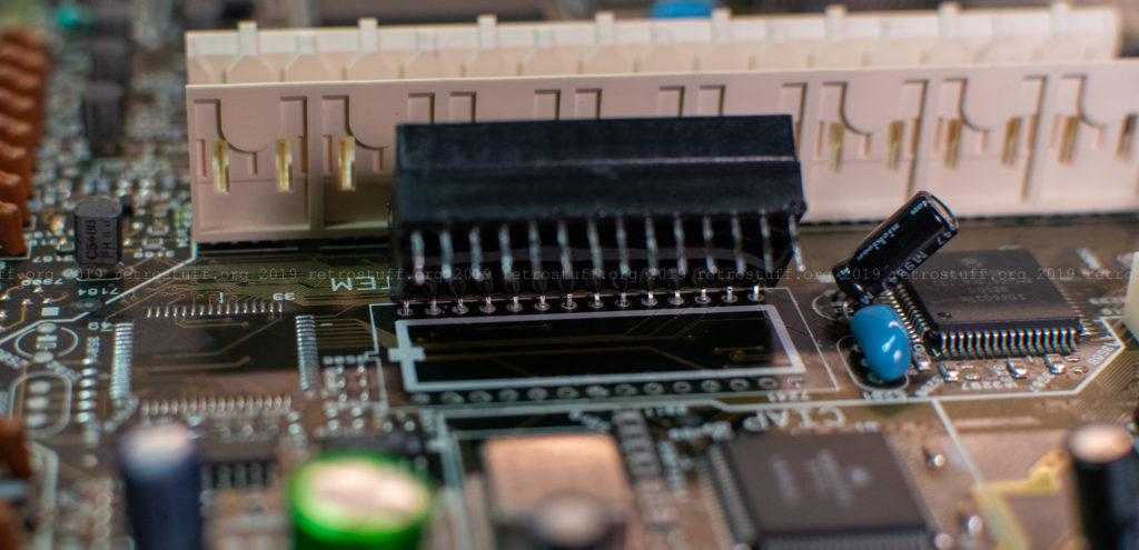
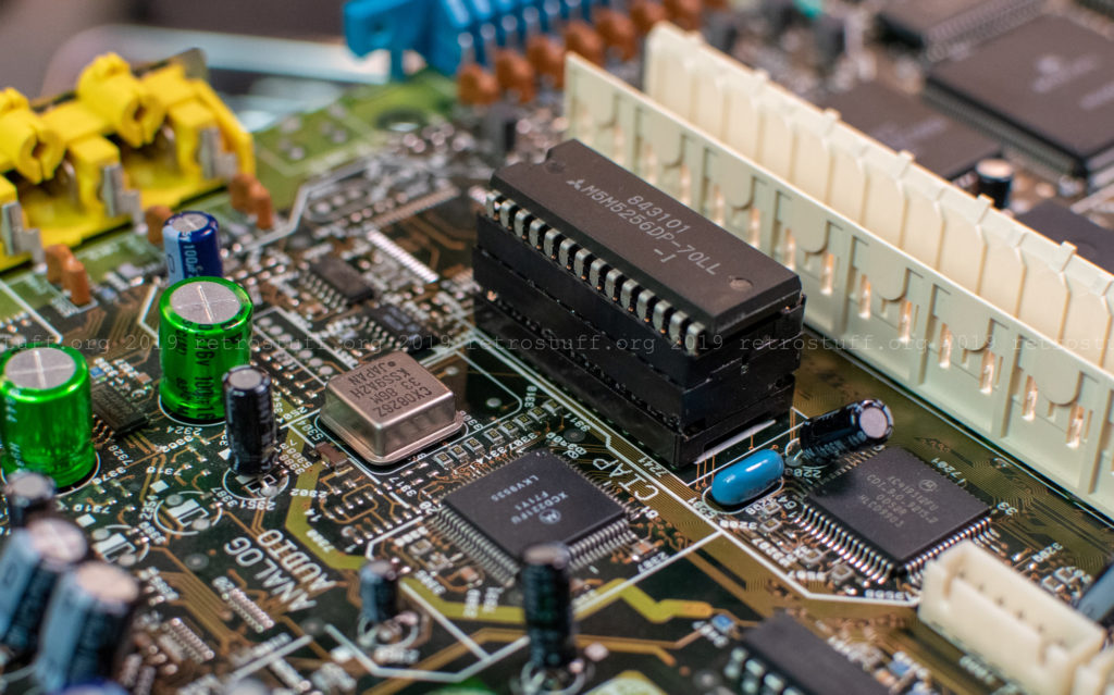
The CDI660 (and other high-end models with Mono II, III and IV boards) do not have the well-known 8KB Timekeeper SRAM chips by SGS-Thomson / STMicroelectronics. Instead, they use a Mitsubishi M5M5256DP-70LL-I 32Kbx8 SRAM chip in a battery-backed Dallas/Maxim DS1216C SmartWatch RAM socket.
Caution: Removing the chip from the socket will instantly delete all the data. Better make a backup first.
Note the C in the socket, this is indeed a DS1216C.
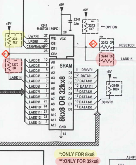
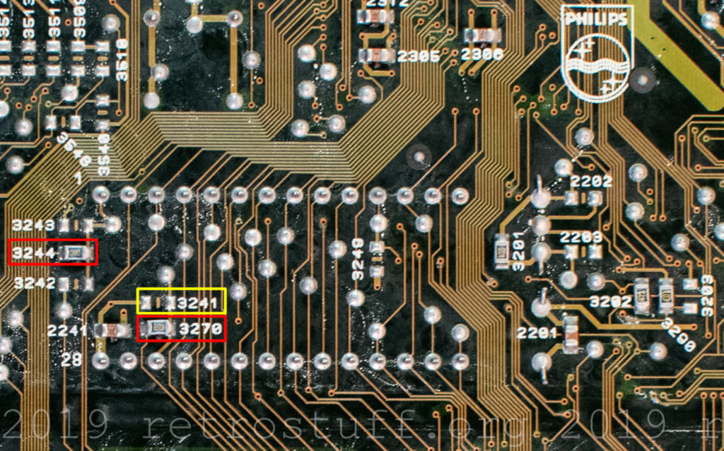
Three jumpers on the mainboard tell the CD-i player the size of the NVRAM. With this knowledge, it should be possible to upgrade the cheaper consumer players with 8 KB NVRAM to 32 KB as well.
Update (2019-12-29): An upgrade has been performed here.
Similar jumpers are also on the Mono II and Mono III mainboards. This is well documented in the service manuals.
NVRAM socket
So far, none of my CD-i players with that kind of NVRAM has shown any memory loss, but it is just a matter of time until the batteries in the sockets will fail too. When researching this topic, I’ve found a tutorial on how to fix this in the DS1216E ROM sockets. It should be similar for the DS1216C RAM sockets. I’m not a fan of these hacks though and always try to use original parts as long as they are being produced. For now, I will only insert an IC socket to make future replacements as easy as possible.
The RAM socket is soldered from both sides and is very difficult to remove. I fixed the Monoboard into a PCB holder to be able to access it from both sides and rotate it when needed, as I did with the CDI605T MMC. Then I desoldered the lower row of pins with a desoldering gun and additional support from a soldering iron on the other side. For the upper row, the DVC socket gets in the way, unfortunately. I had to carefully bend up the RAM socket to access and desolder the remaining pins.
This took a while, but eventually worked out fine. After cleaning the PCB, I fitted a 28-pin IC socket.
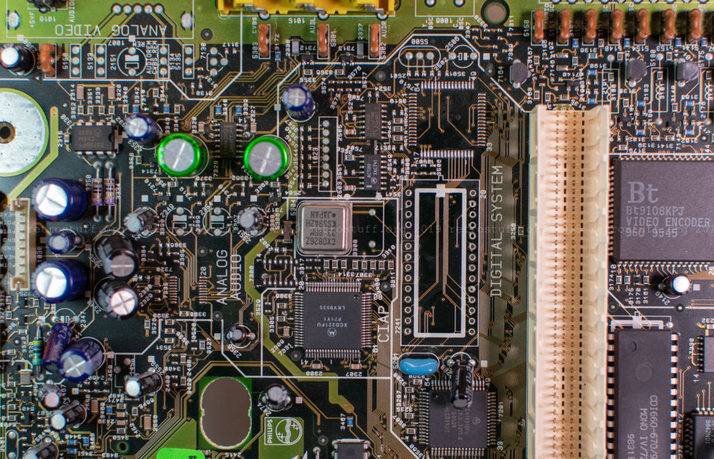
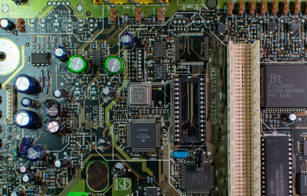
Then, I put back the RAM socket and the SRAM chip. This is quite a sandwich, but there is plenty of space left underneath the CD tray.
60 Hz modification
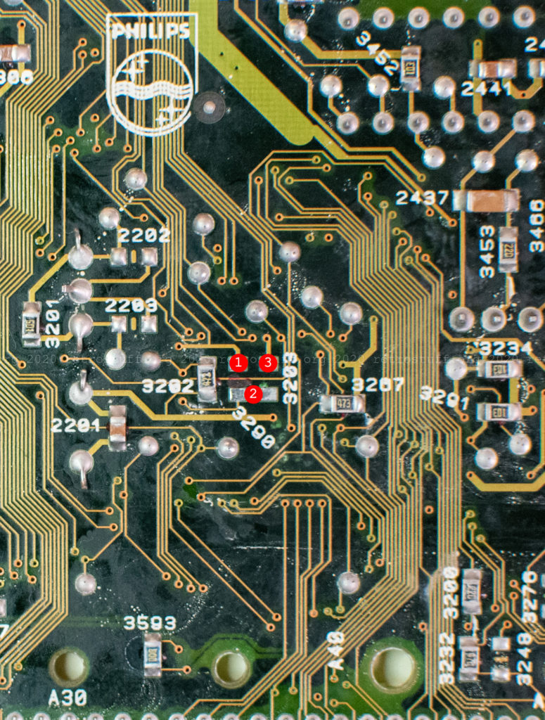
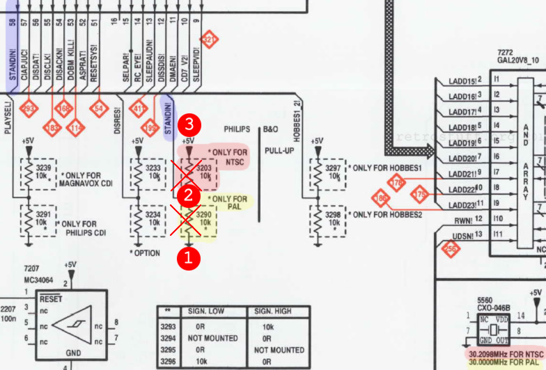
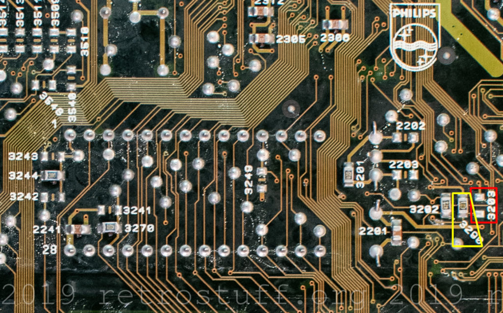
The STANDIN! signal on pin 58 tells the CPU if the CD-i player is from the PAL or NTSC region and changes the frequency of the video output to either 50 or 60 Hz. Two jumpers (10 kΩ resistors) 3203 and 3290 set the signal.
As long as the video is output via RGB-SCART, most TVs will accept and display it in full colour. The CDI660 has a SCART socket and outputs RGB just fine. Smaller consumer players (CDI470 and CDI490) and non-European players have composite and S-Video outputs. They cannot handle this modification and will only output a black and white picture. To change the video output into proper PAL or NTSC, you will have to change the crystal oscillator as well. I’ve been trying to source down matching crystal oscillators for years, without success.
I removed the resistor 3290 and cleaned the pads. Then I added three wires and secured them. (1) = GND, (2) = STANDIN! and (3) = +5V.
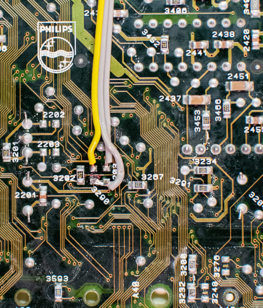

I soldered a 10 kΩ resistor to the centre pin of a SPDT (single pole, double throw) switch and the three wires to the outer pins and the resistor. Then I secured everything with heat shrink tube.
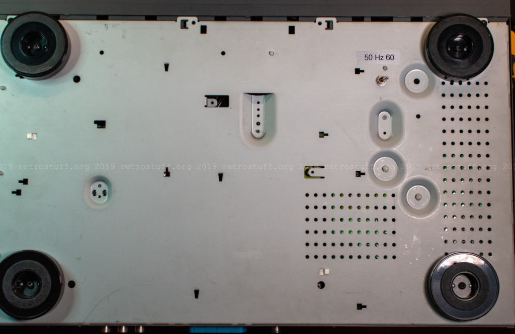
One reason that this has been on my to-do list for so long is that there are no places to put a switch in the CDI660 case without destroying it. However, I’ve found the perfect place now. There are two holes in the bottom case that are big enough to hold the switch. I chose the hole on the right side of the player, the other one is underneath the CDM assembly.
The switch is shorter than the feet and won’t touch the ground.



The NVRAM modification probably will not work. See my comment on TheWorldOfCDi before you try it!
You’re right. It took me a while, but here are the results: https://retrostuff.org/2019/12/29/philips-cdi470-32-kb-nvram-upgrade/