
In this article, I’ll upgrade a Philips CDI450 with 32 KB NVRAM. You’ll find all information that is needed to modify the system ROM and the mainboard. If this sounds familiar – yes, it does: In 2019, I explored the possibility to upgrade a CDI470. Even though patching the system ROM failed back then, the experiment was still a success. The final solution to access 32 KB NVRAM was to use the ROM of a 490. As it turned out later, this was also Philips’ solution for the 470/85 model, but that is a topic for another article.
With the 450 (and all other top-loading players with Roboco mainboard) it is a bit different: It’s a low-cost model with 8 KB NVRAM only. The mainboard was neither prepared for a bigger NVRAM solution nor is there a similar advanced model that I could borrow the system ROM from. This time, a ROM patch must succeed.
Earlier this year, I had a break-through with successfully patching the ROM of a digital video cartridge to add a missing module to a CDI660. Right after that, I experimented with a CDI450 system ROM.
Note: Some information and techniques have already been covered in the previous articles. I won’t go too much into details now, so please read these articles for more information: Philips CDI470 32 KB NVRAM Upgrade and Philips CDI660 Service Shell.
The second experiment
To access the NVRAM, a CD-i player needs two modules in the system ROM: nvr (device descriptor) and nvdrv (device driver). The size of the NVRAM is defined in the device descriptor option field PD_RSIZ (8 KB / 32 KB / auto-probing).
In the last experiment with the 470, it became very clear that changes to only nvr and nvdrv can lead to undesired results (e.g., unreliable clock and data loss). This is why another module is needed: sgstom or ds1216 (system modules / RTC drivers). As you can probably guess by the names, sgstom is for the 8 KB Timekeeper chips by SGS-Thomson / STMicroelectronics and ds1216 usually* for the 32 KB DS1216C SmartWatch RAM sockets by Dallas / Maxim. Combined with matching nvr and nvdrv modules, we will get a working RTC with either 8 KB or 32 KB NVRAM.
*To keep things interesting, there are 3-4 variants of the ds1216 module.
For this experiment, I focused on the latest and largest version of the ds1216 module (CRC A59E7B, 908 bytes): It only appeared in the later 490 and 660/670 system ROMs and supports both types of RTC. To quote CD-i Fan: “Depending on system global at $7E5(a6), or absolute memory address 1CE5, it will choose a branch (nonzero is SGS, zero is Dallas).”.
Its accompanying nvr module has PD_RSIZ set to $0000 (auto-probing), which allows flexible NVRAM solutions.
Replacing and patching modules
I checked the three modules in the system ROM of a 450/00 (cdi450a14.rom, ID 50, R1.4, CRC32 957FCD41):
| Address | Size | CRC | Module name |
|---|---|---|---|
| $162DA | 550 | B29131 | sgstom |
| $16824 | 774 | E18B45 | nvdrv |
| $16B2A | 94 | E9B44E | nvr |
| Total: | 1418 |
And did the same with a system ROM of a 490/00 (cdi490a17.rom, ID 77, R1.7, CRC32 9A10DA73):
| Address | Size | CRC | Module name |
|---|---|---|---|
| $165AE | 908 | A59E7B | ds1216 |
| $16C5E | 878 | D6E902 | nvdrv |
| $16FCC | 98 | 191C24 | nvr |
| Total: | 1884 |
Note: This also applies to the system ROM of a 470/85 (cdi490a16.rom, ID 77, R1.6, CRC32 E115F45B), which is the very same 490 ROM that can the found in MAME in big-endian format (cdi490a.rom, CRC32 E2F00F6).
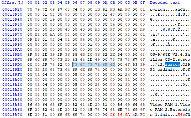
To replace the three modules, I needed 466 bytes of extra space. Luckily, there was enough space left in the dummy module (1792 bytes at address $7F8F2). I resized it, fixed the header and calculated the checksum. Next, I replaced the three modules, starting with nvr, then nvdrv and finally ds1216. The last step was to calculate and write the checksum of the patched ROM file.
I didn’t expect too much of this and wasn’t surprised when it didn’t boot at all in the CD-i Emulator.
The missing piece
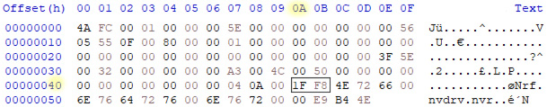
Five months later, CD-i Fan and I were comparing module differences of 210 and 220 system ROMs. He mentioned the data module init. And there it was, the last missing piece of the puzzle: Of course I needed to tell the system which RTC driver it should load, and this was done in the module init:
Because sgstom and ds1216 have the same number of characters, the change was very easy. No extra space was needed this time, only new checksums for the module init and the ROM file.
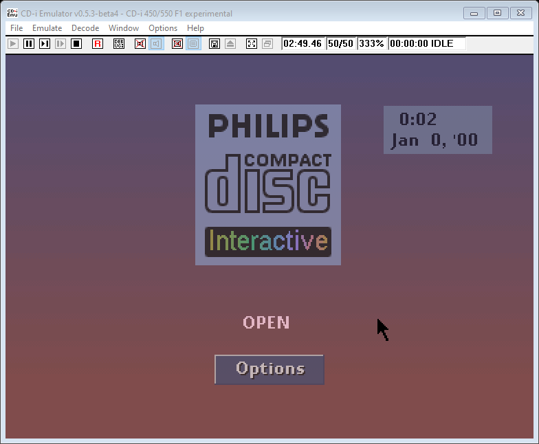
It booted right away in cdiemu (don’t mind the weird date/time; the DS1216C RTC isn’t emulated yet):
Preparing the CD-i player
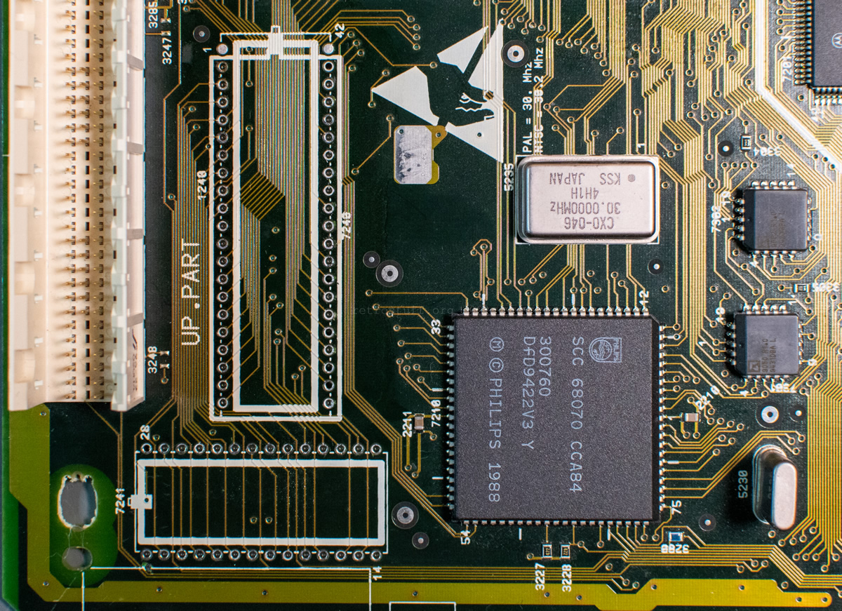
As mentioned before, Roboco mainboards weren’t meant to have 32 KB NVRAM. The jumpers to the address lines that you can find on other mainboards are missing – at least in the three board revisions that I have examined so far (two of them can be seen in this article).
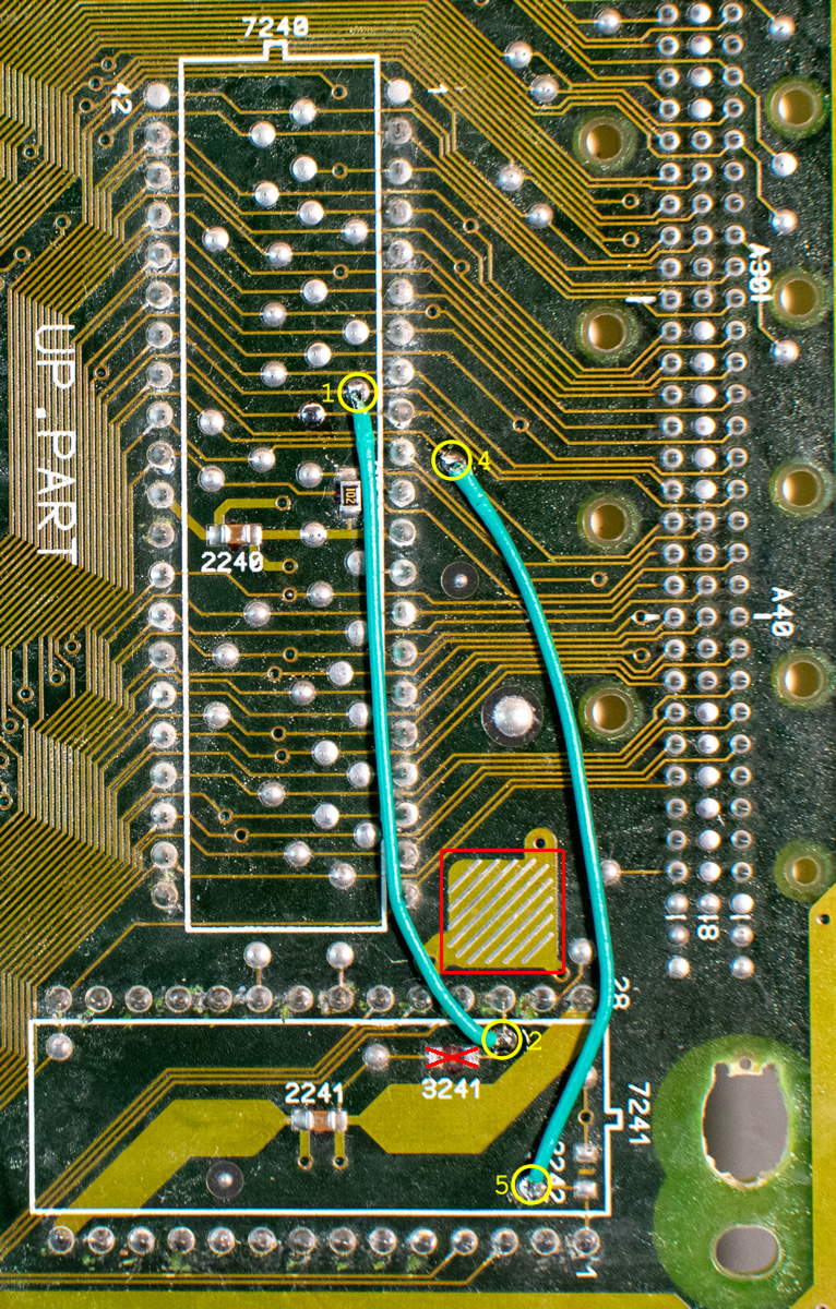
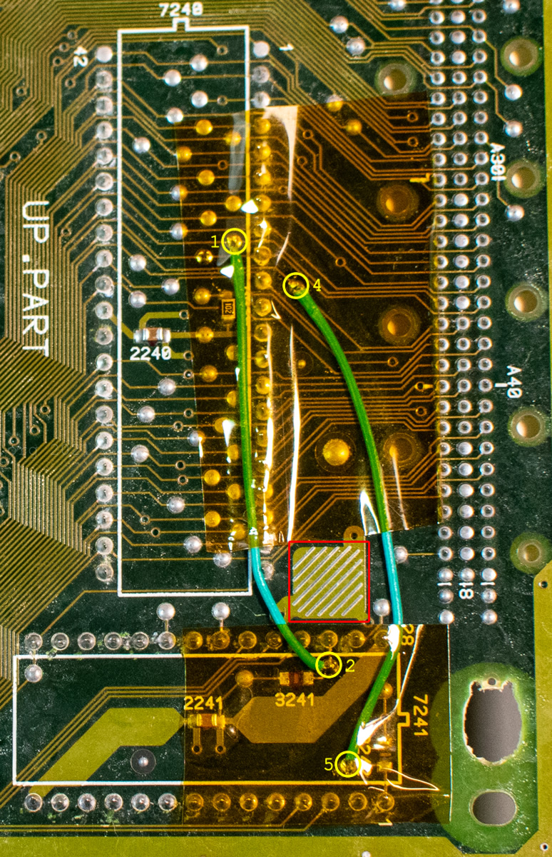
There are two test points close to the system ROM that we can use instead:
(1) TP 459 on LADD14! between pin 35 (A13) of the system ROM and pin C36 of the extension connector.
(4) TP 474 on LADD15! between pin 34 (A14) of the system ROM and pin C37 of the extension connector.
Note: The 40-pin system ROM sits on a 42-pin footprint. When reading the schematics, subtract 1 from the pin numbers.
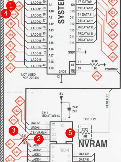

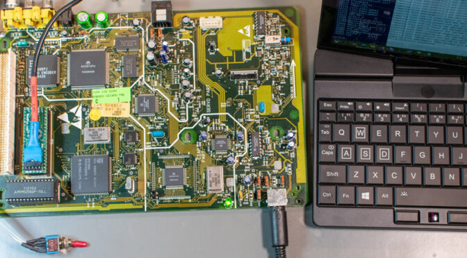
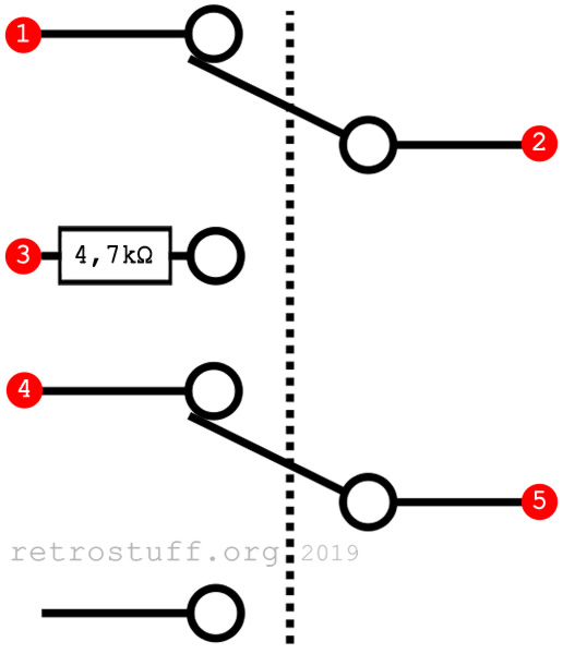
One of the CDI450 that I swapped the laser sledge for last month already had Timekeeper and system ROM in sockets, so it was a good candidate for the tests. I removed resistor 3241 and soldered the DPDT (double pole, double throw) toggle switch with the 4,7 kΩ resistor from my 470 NVRAM test setup to the indicated points:
Testing
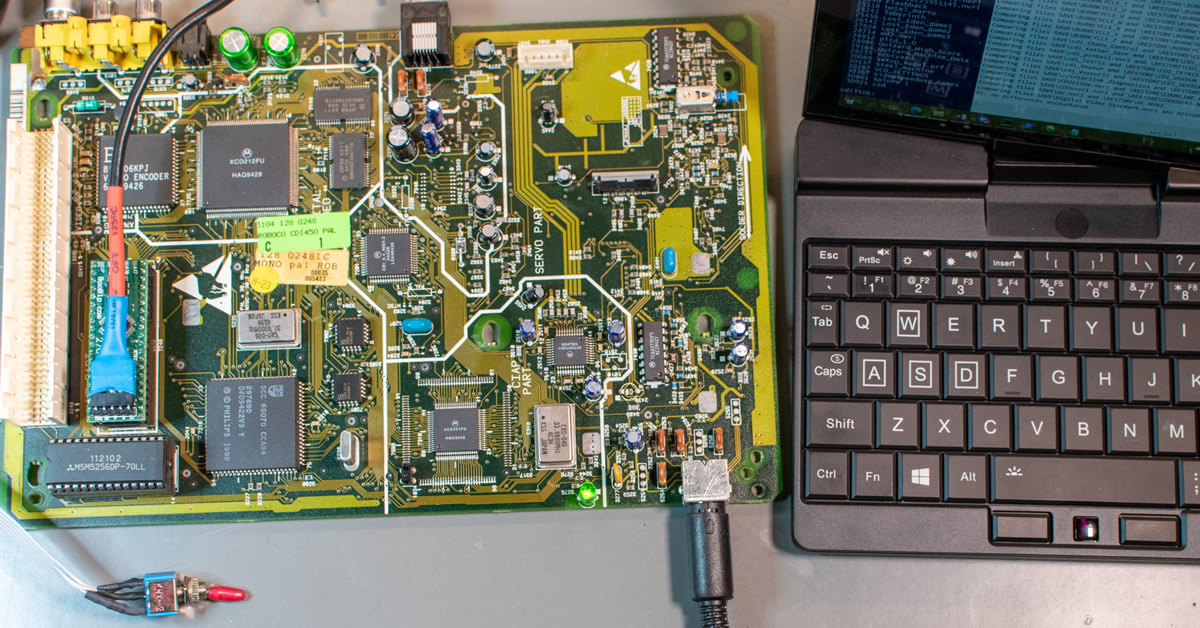
I programmed the patched ROM to a 27C400 EPROM emulator and tried it in my CDI450:
There’s not much to say about this, it worked right away with 32 KB NVRAM. Since I didn’t have a lot of time, I only downloaded some files to the NVRAM, uploaded them again to my PC and did a binary check that turned out to be successful.
Two weeks later, I finally had some time to go through the full test protocol that I used before for my CDI470 modification. I made some additional tests and changed the order, to catch every possible error.
1. Low-level test via terminal
2. Playing Earth Command (sensitive to missing RTC)
3. Downloading a lot of files via batch script into NVRAM (32 KB = 95% / 8 KB = overloading)
4. Playing Burn:Cycle (loading and saving files)
5. Service Shell
6a. Changing date/time/settings in the shell
6b. Clock calibration (Low-level test item 7; 8 KB only)
7. Uploading the contents of the NVRAM to the PC
8. Binary check of the downloaded and uploaded files
9. Checking RTC in shell/in game/after communicating with cdilink and after the player was switched off.
All of these tests were performed successfully with the following NVRAM solutions:
8 KB: ST MK48T08B-15 Timekeeper with new BR1225 battery (hacked).
32 KB: 1) Dallas DS1216C socket + M5M5256DP SRAM; 2) Dallas DS1244Y.
Philips CDI450 32 KB NVRAM Upgrade
Warning: This is an experimental modification. I did not test all possible combinations of mainboard and system ROM revisions. The configuration that I used the most was board revision .4 that came with system ROM R1.1.
Backup your NVRAM data first and proceed at your own risk!
Take care of the system ROM first: If it sits in a socket then pull it and if it is soldered to the mainboard then desolder it. This makes it easier to reach the Timekeeper chip that you should desolder next. Desoldering needs fresh solder and plenty of flux, a powerful desoldering gun, desoldering wick and a lot of patience.
If the system ROM doesn’t have a socket, then solder a 40-pin socket into the smaller footprint (leave pins 1 and 42 empty).
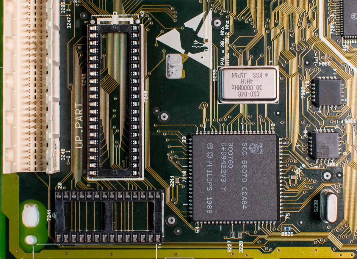
Do not add a socket for the NVRAM before you have read the following section!
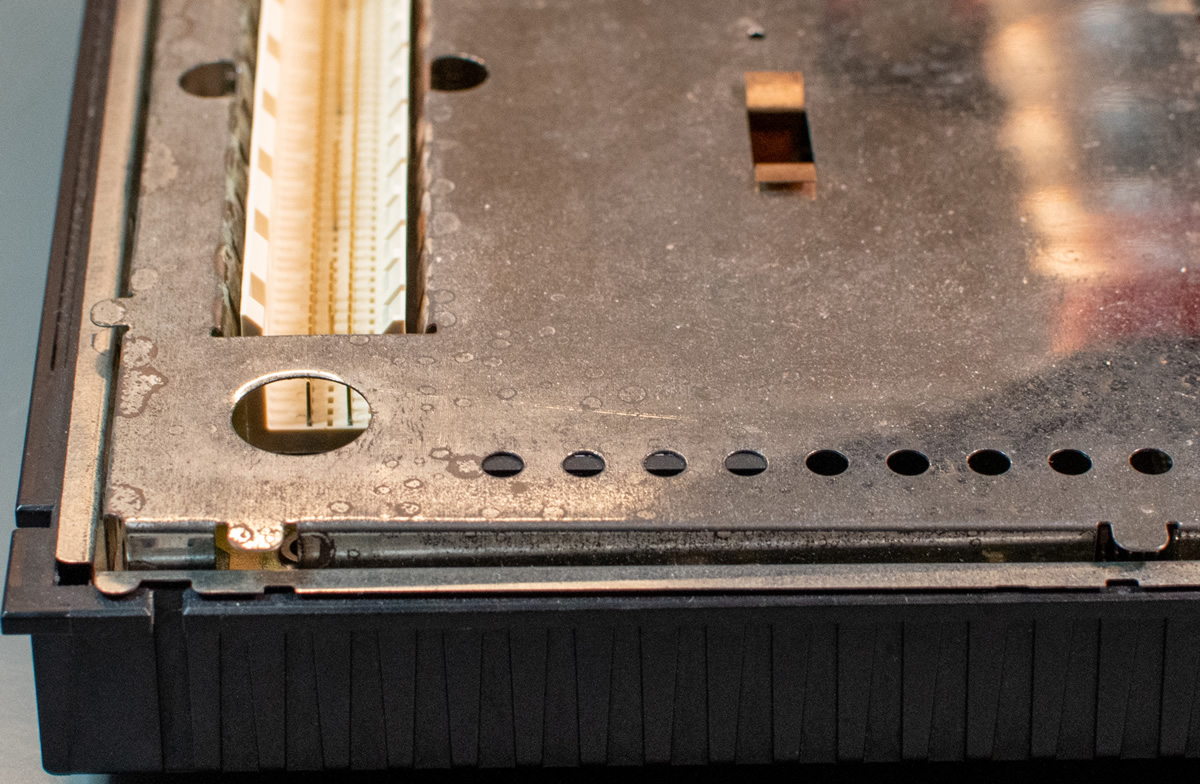
NVRAM height
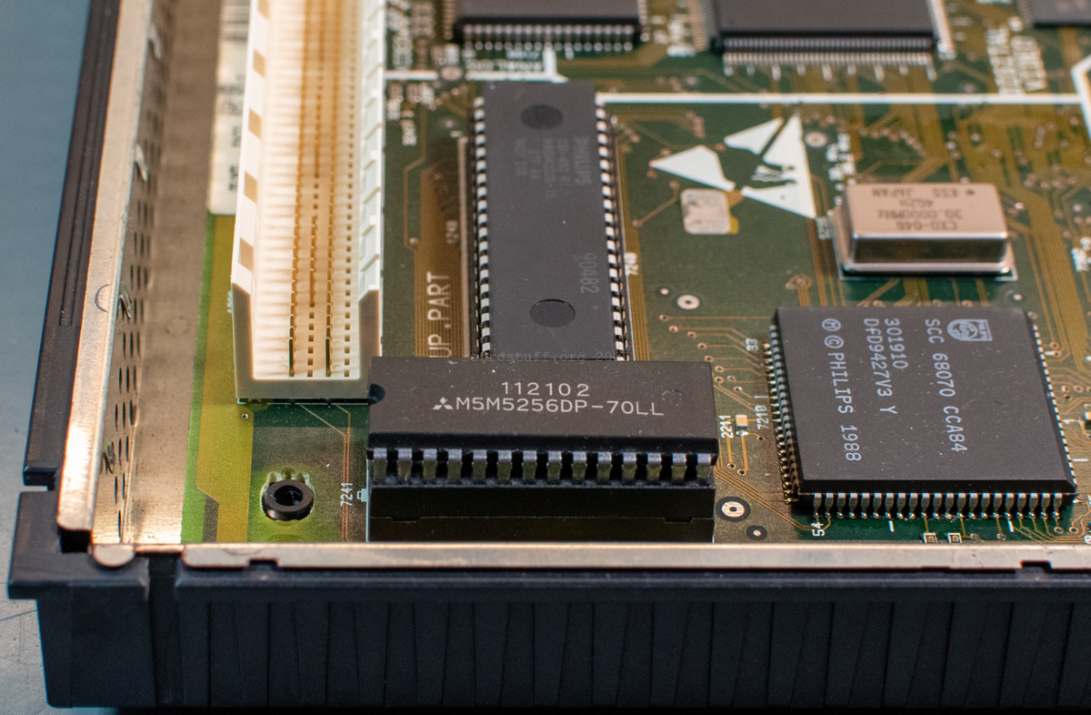
Let’s have a look at different NVRAM solutions before we continue. From left to right: DS1216C w/ SRAM, DS1216C w/out SRAM, DS1244Y, DS1643, M48T08, MK48T08B.

While it is possible to squeeze an 8 KB solution with extra socket into a 450 (depending on socket and potential modification), it is almost impossible for 32 KB solutions.
The DS1216C + SRAM sandwich is too tall, even if you solder it directly to the mainboard.
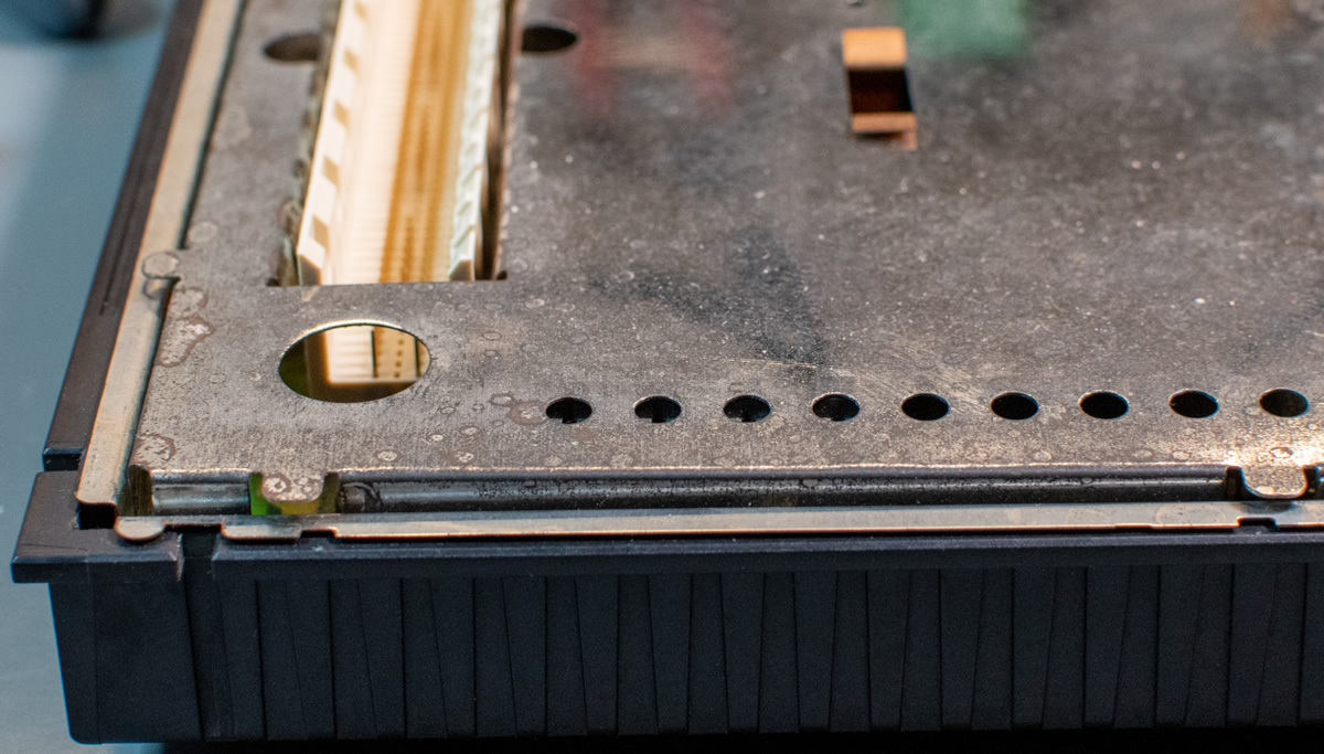
If you cut a hole into the metal shield and into the plastic top cover, then you can’t use an additional socket because it will bump into the DVC. That means that you’ll have to do all possibly needed repairs / modifications beforehand (e.g. cutting the connections to the internal batteries and adding an external battery, see the 32 KB NVRAM section).
If you don’t want to cut holes into your CD-i player then you can use a replacement with lower height: Dallas / Maxim DS1244Y-70+. And once again, that chip needs to be soldered directly to the mainboard or it will be too tall.

Update: An alternative is the Glitch Works GW-1244-1; even when it is in a socket, it barely touches the metal shield.
Back to the socket for the NVRAM solution:
I recommend using a socket for testing. You don’t need metal shield and top cover to play discs (see this article for details). However, make sure that you can remove it easily when done with the tests. I didn’t use any flux and only as little solder as possible to prevent it from flowing through the holes and giving me a hard time again.
Mainboard modification
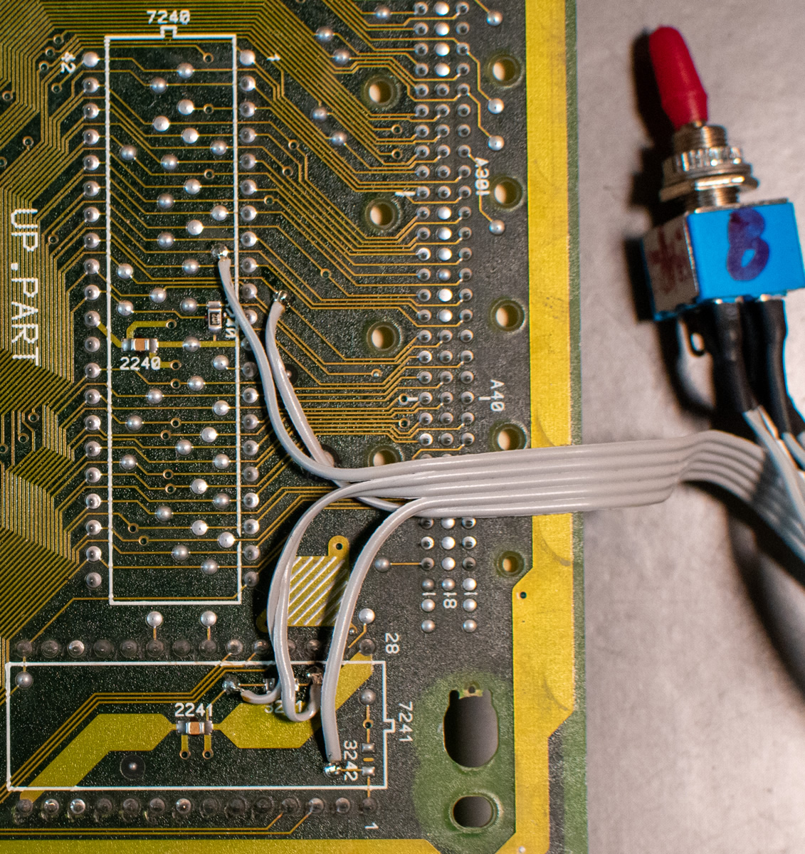
You could keep the setup flexible by using the switch from above and hiding it inside the player (if you find some space). If you opt for a permanent 32 KB modification, then route two wires from (1) to (2) and from (4) to (5). Do not forget to remove resistor 3241 next to (2).
Pay special attention to the hatched area in the red square. This is a ground contact for the lower metal shield and must not be covered by wires or insulation.
ROM patches
I made one additional change to the ROM file and raised the revision to R2.4 to not mix up the already known revisions.
If you want to try it out yourself and don’t want to go through all the manual patching, here’s an archive with experimental patches.
Use the Delta Patcher (source code) to apply them to one of the following system ROMs:
cdi450a11.rom – ID 50, R1.1, CRC32 F1457017
cdi450a13.rom – ID 50, R1.3, CRC32 164D5467
cdi450a14.rom – ID 50, R1.4, CRC32 957FCD41
Note: You’ll have to dump these ROMs from your CD-i player. The file names might differ, depending on the version of CD-i Link. If you dumped the ROMs with an EPROM programmer, then you’ll have to convert them to little-endian format first (e.g., with the SRecord tools).
When you’re done patching then you’ll get a cdi450a24.rom (ID 50, R2.4, CRC32 ACEE3B44) with 8 and 32 KB NVRAM compatibility. Convert the file to big-endian format and program it to a 27C400 EPROM to use it in your CD-i player.
If you discover bugs, need additional help or a patch for an unknown system ROM, feel free to reach out to me. You can do so in the comments, via the contact form or on the Philips CD-i Community Discord server.
4 thoughts on “Philips CDI450 32 KB NVRAM Upgrade”