
It has been on my table for a while to figure out a working Philips CDI490 RGB SCART modification. The topic caught my interest when it came up in the community on The world of CD-i last year. Back then, I thought it would be quite easy because the small 470 and 490 CD-i players share a certain mainboard (Mono IV) with their big brothers 660/00, 220/80 and 210/60. There are only some components missing that could be figured out by looking at the service manuals.
However, I couldn’t try it out back then because I didn’t have a working 470 or 490. I focused on repairing my 470 first and then adding a PAL/NTSC switch. Eventually, I bought the needed components and two broken 490s to experiment with.
My goal is to implement features the way Philips would have done it (and also did to the bigger Mono IV CD-i players). If you are looking for an RGB implementation without stock components and a SCART socket, then have a look at this article for alternatives.
Preparations
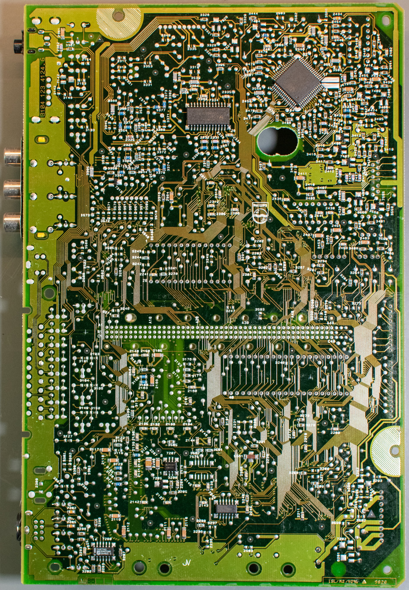
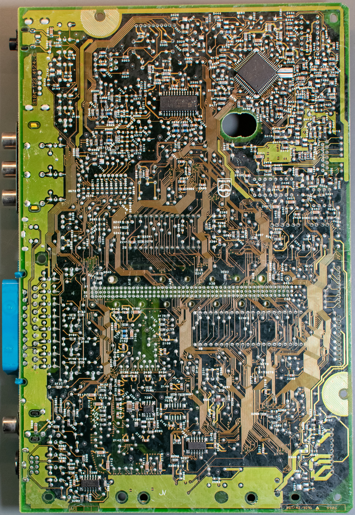
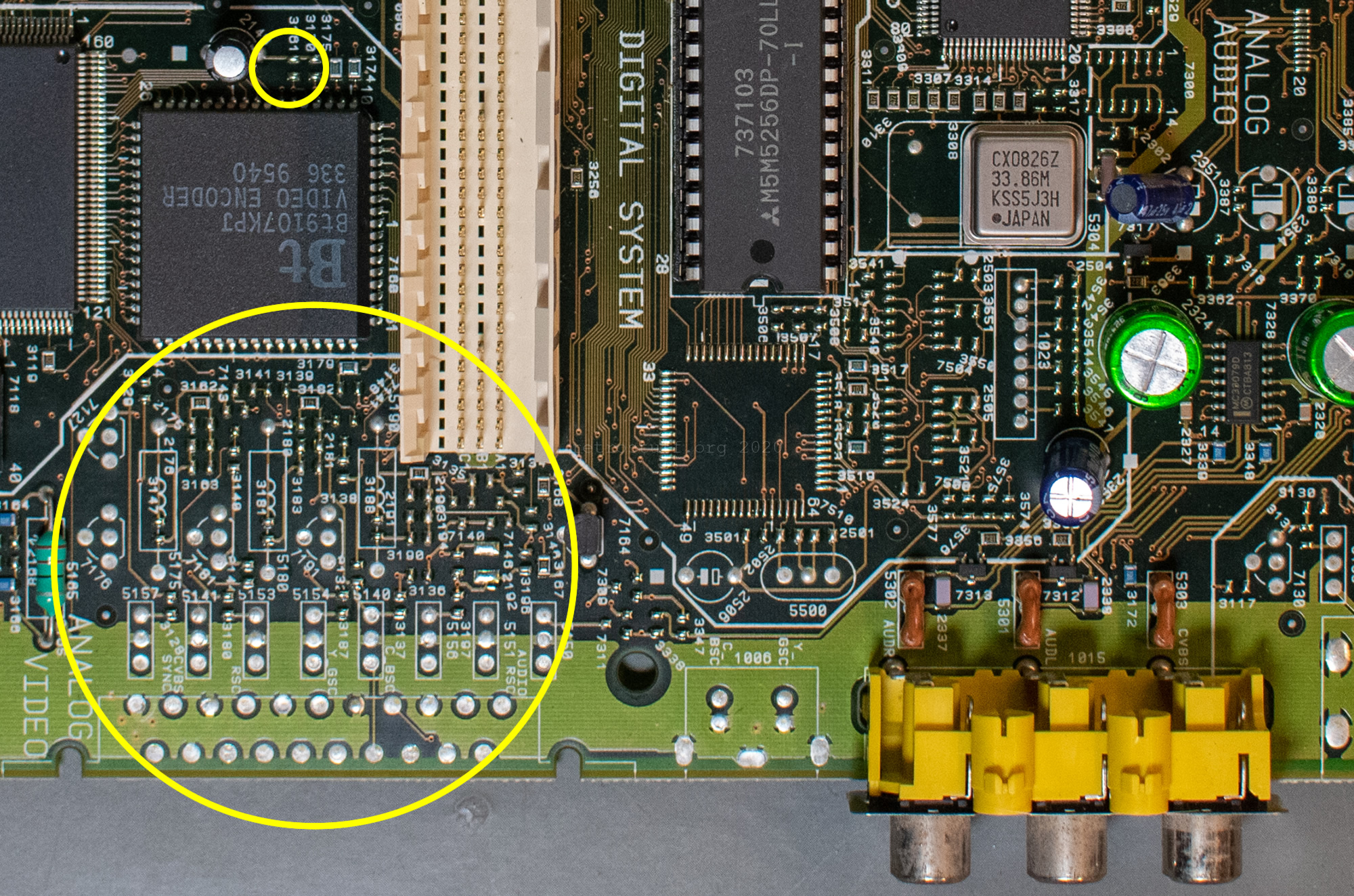
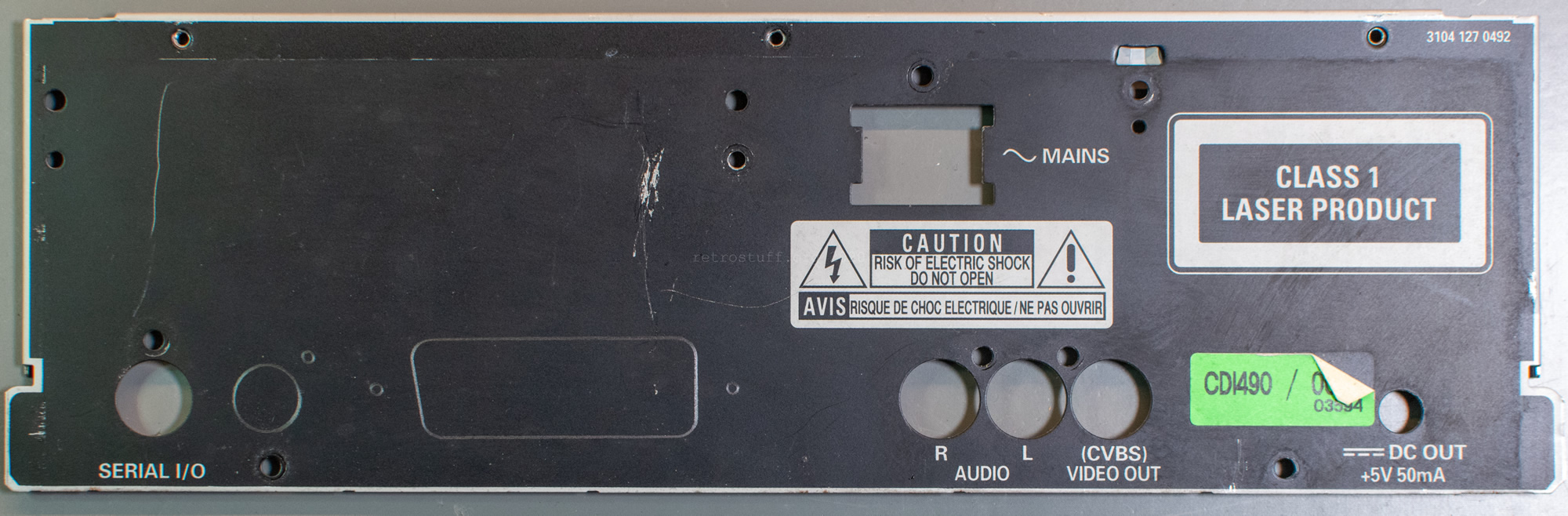
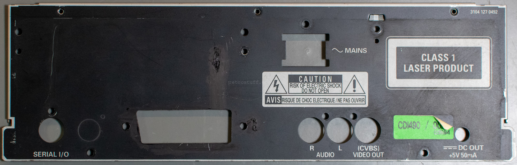
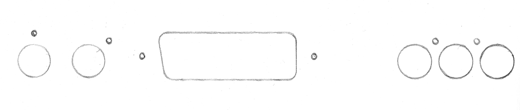
Let’s have a look at the working areas first. The big circles are the grid squares D4 to E4 on the front and the back. This is where the video and switching signals components will be placed. The medium circle on the back (grid squares A4 to B4) is for the audio components. Lastly, the small circles on the front and back (grid square E3) is where the video output is set.
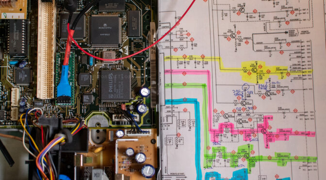
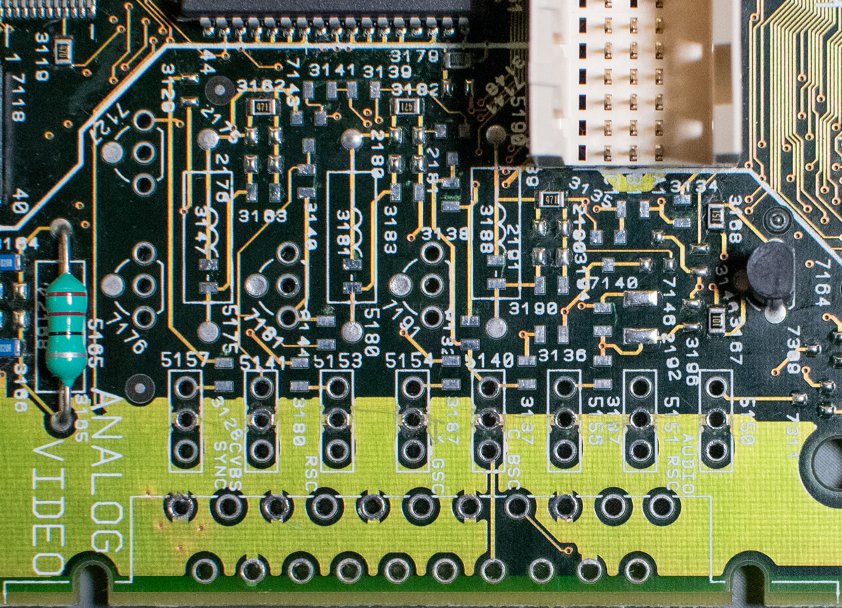
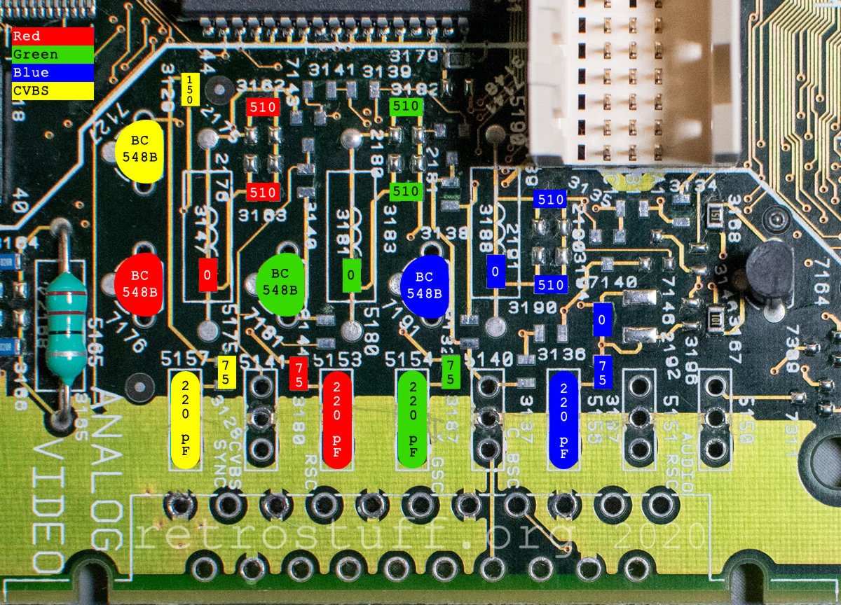
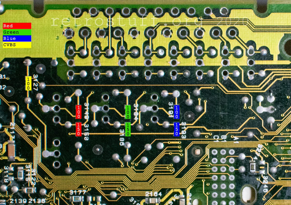
This is a map for the components that can be placed in the big area on the front (D4 – E4). Not every signal/component is needed, but more about that later. You will find the list of all components at the end of the article and explanations on the way.

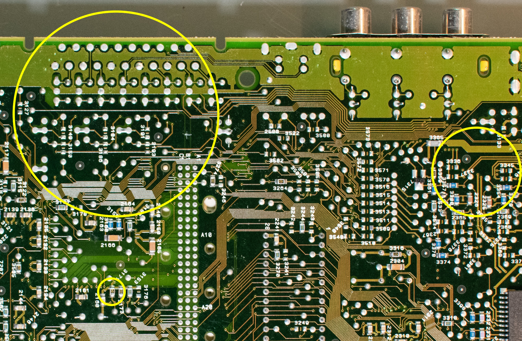
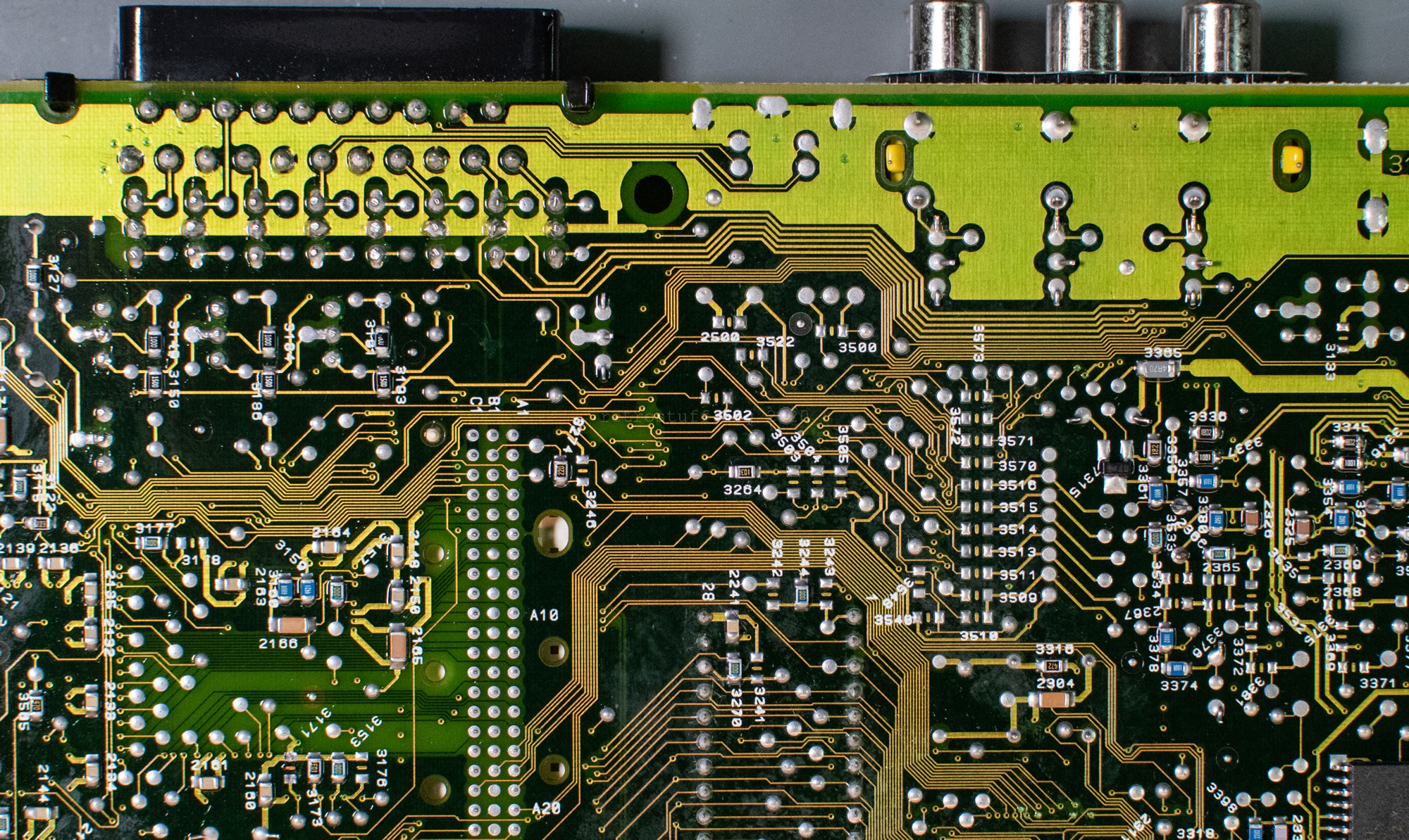
Before placing new components, unneeded components and old solder need to be removed. Especially the solder that covers the holes of the through-hole components and is connected to the ground plane needs a powerful desoldering gun with higher temperature than normal (~400 °C).
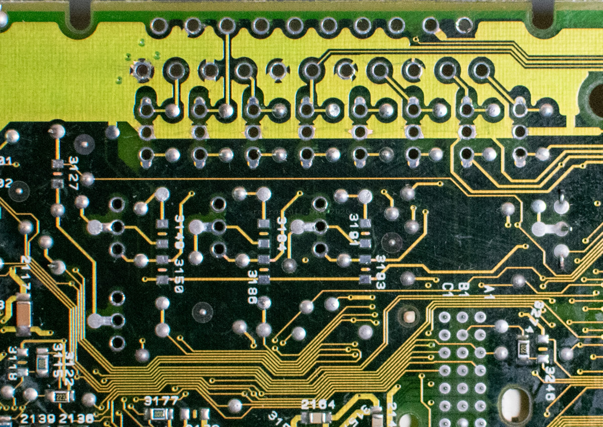
This is the area after the initial clean-up (I forgot to remove three resistors and two pads):
Enable RGB output
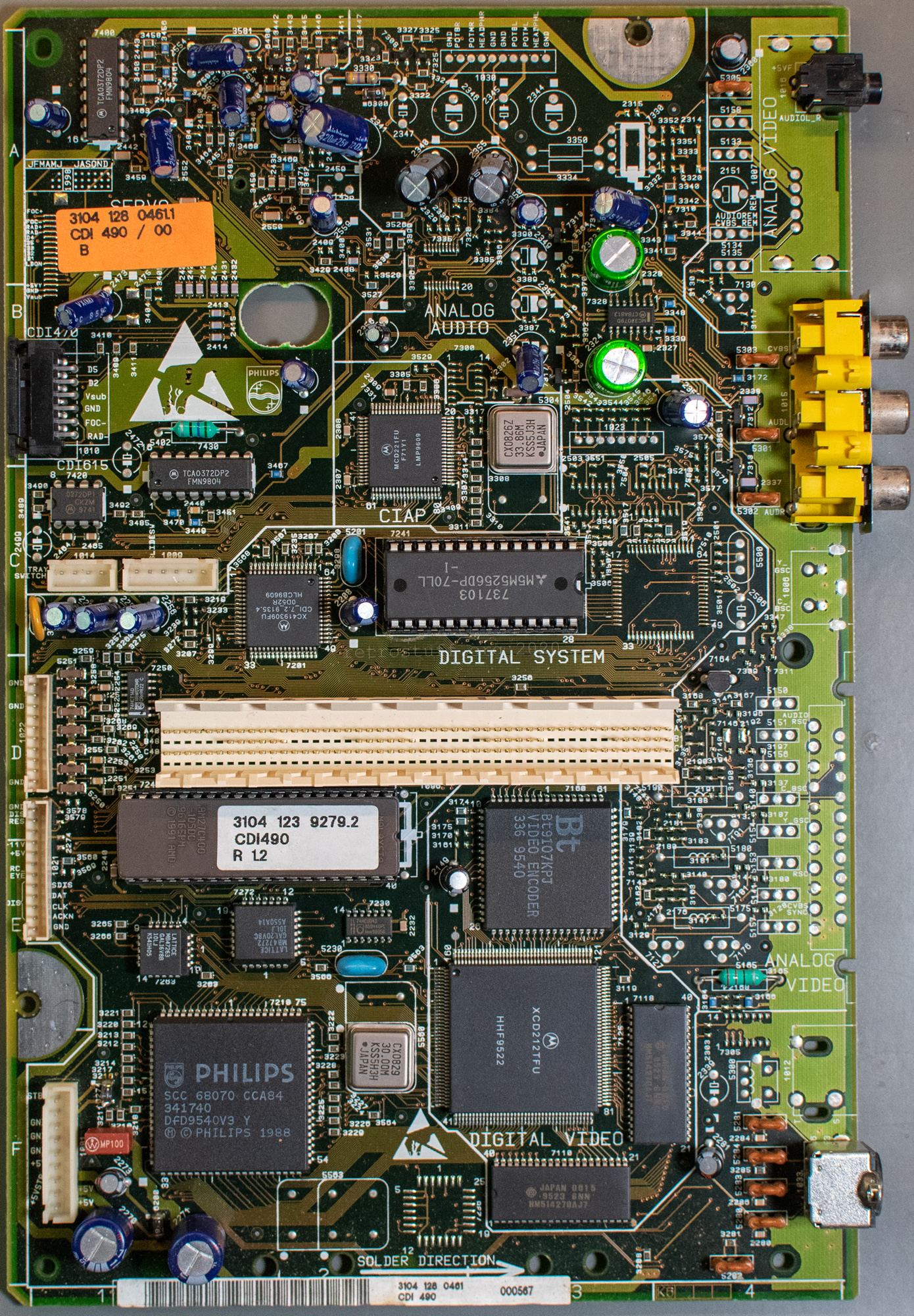
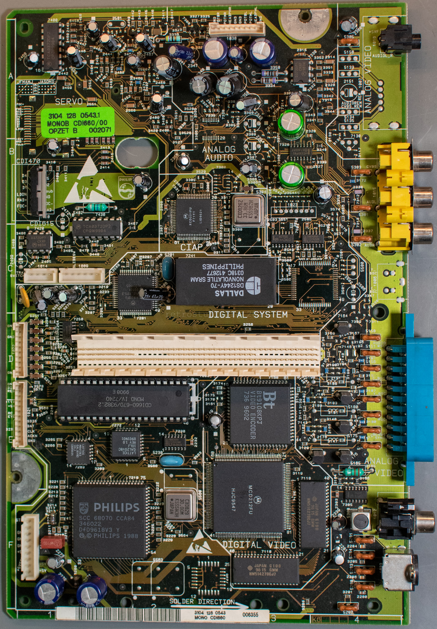
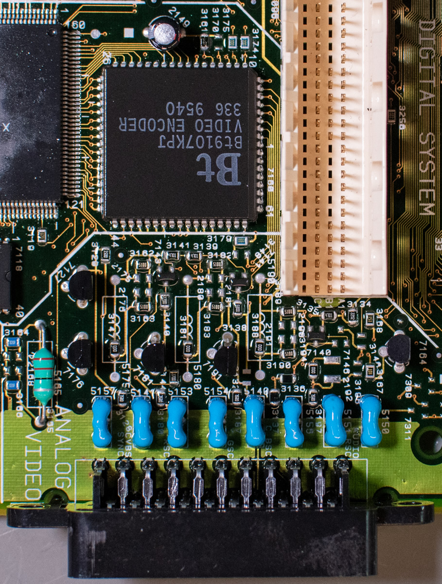
All Mono IV mainboards have a Brooktree BT9106 / BT9107 / BT9108 video encoder. Philips calls them Calvin & Hobbes in the service manuals. A resistor on pin 14 (RGBout) sets the video output:
3171 in E3 (back) – 1 kΩ to GND
Video signals: Composite (CVBS) and S-Video (Y/C)
Output pins: 2 CVBS, 4 CVBS, 8 luminance / Y, 6 chrominance / C
3161 in E3 (front) – 1 kΩ to +5 V
Video signals: Composite (CVBS) and RGB video
Output pins: 2 CVBS, 4 red / R, 8 green / G, 6 blue / B
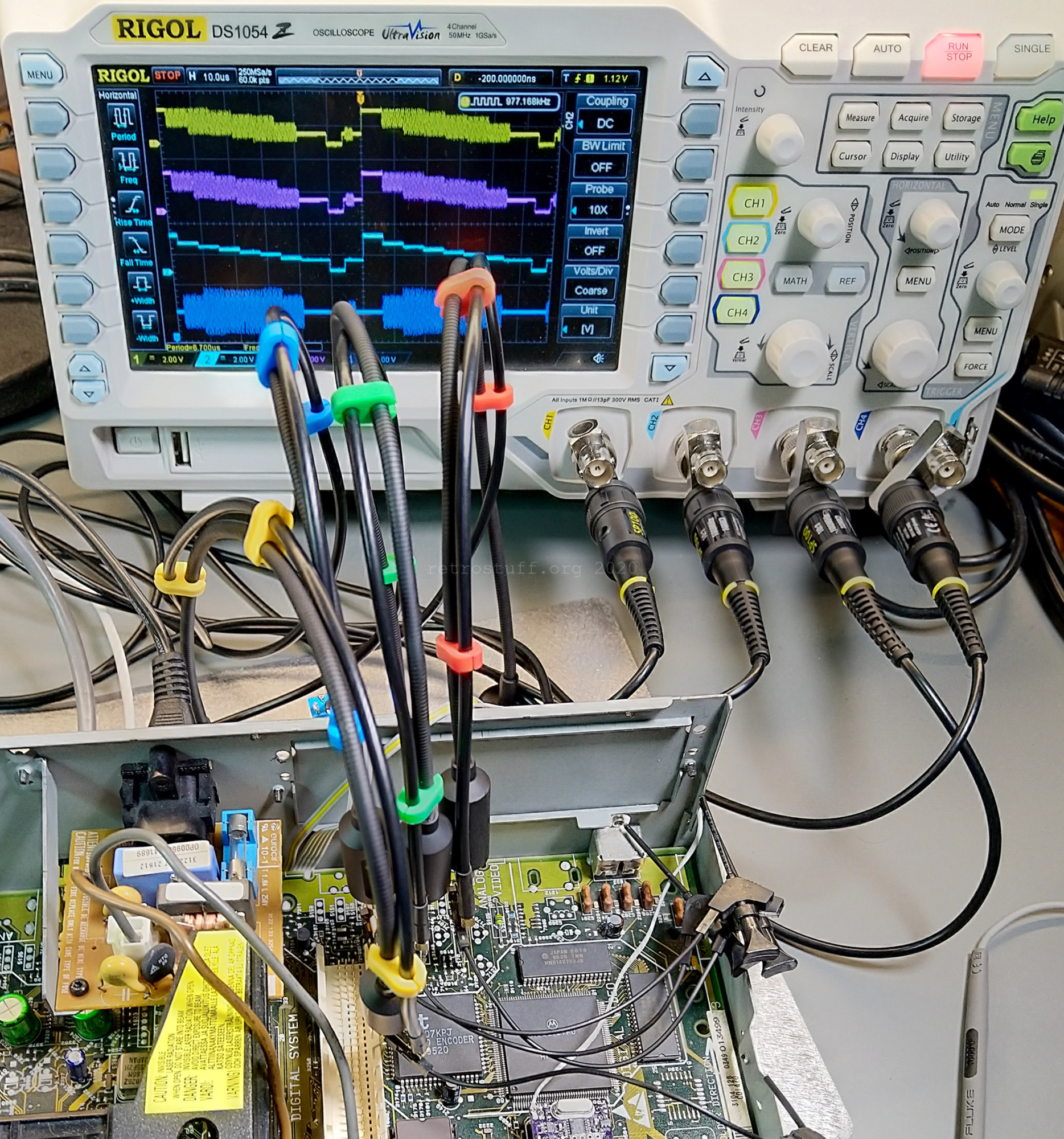
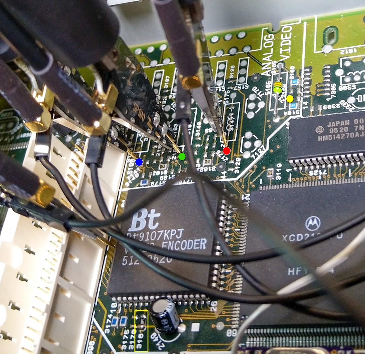
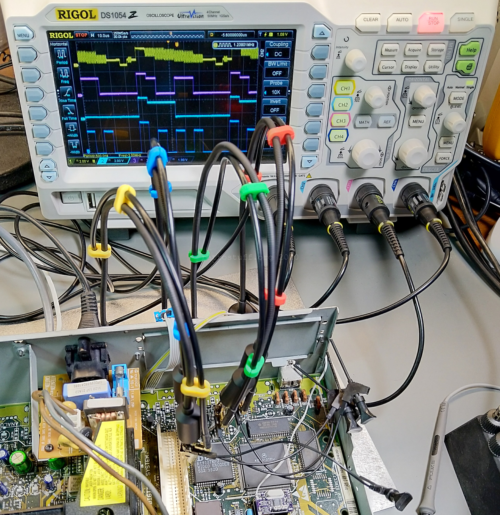
I already did that to my 470 earlier this year; here are some pictures of oscilloscope readings before and after adding the resistor 3161. I’ve marked the position of resistor 3161 in the second picture and also the test points for red, green, blue and CVBS. For CVBS, I placed the probe directly onto pin 2 of the video encoder, but there is a much better point to the upper right of red.
I accidently left resistor 3171 in place and RGB was still enabled. That only confirms that you cannot have both S-Video and RGB video output at the same time. You could however install a switch that sets pin 14 with a 1 kΩ resistor to either +5 V or GND if you want to keep both options.
Now, with RGB output enabled, we can move on to add the components for the video signals.
Bad RGB
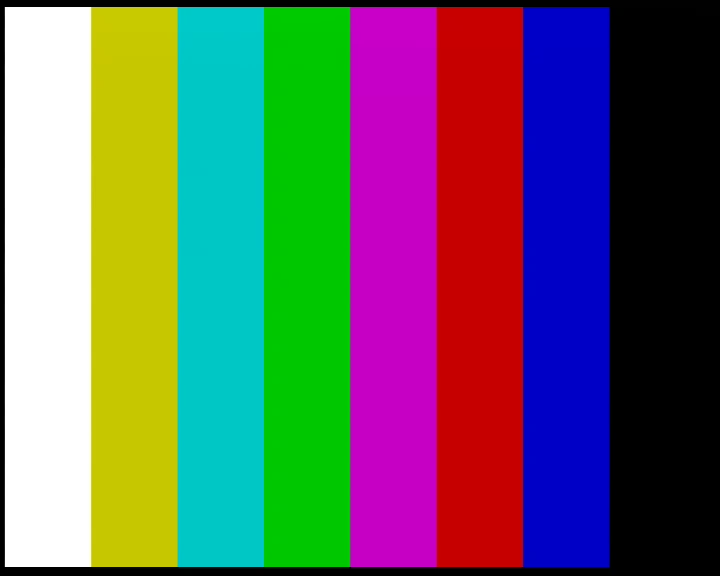
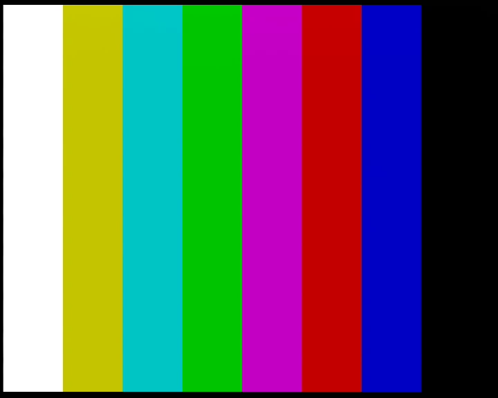
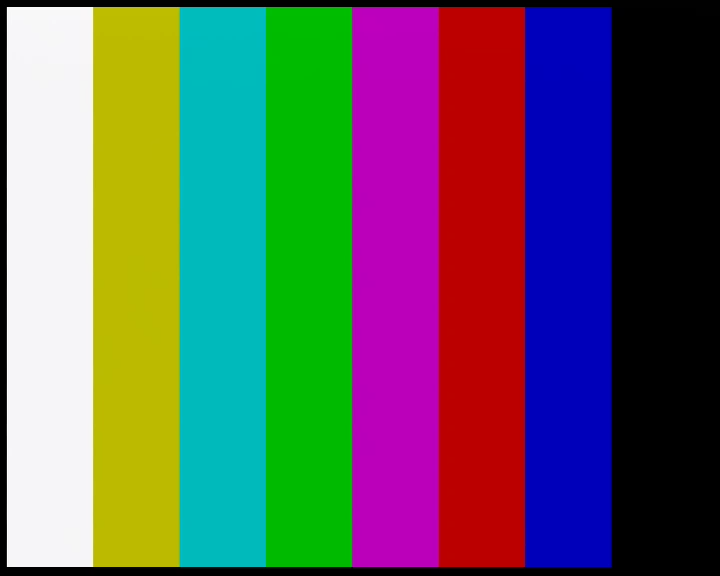
I placed all components for RGB, CVBS, audio and the SCART socket according to the service manual and ran the first tests. It turned out that the RGB video did not match the output of other CD-i players or even the CVBS output. Here’s a comparison between RGB and CVBS output of the 490 (left) and 660 (right):
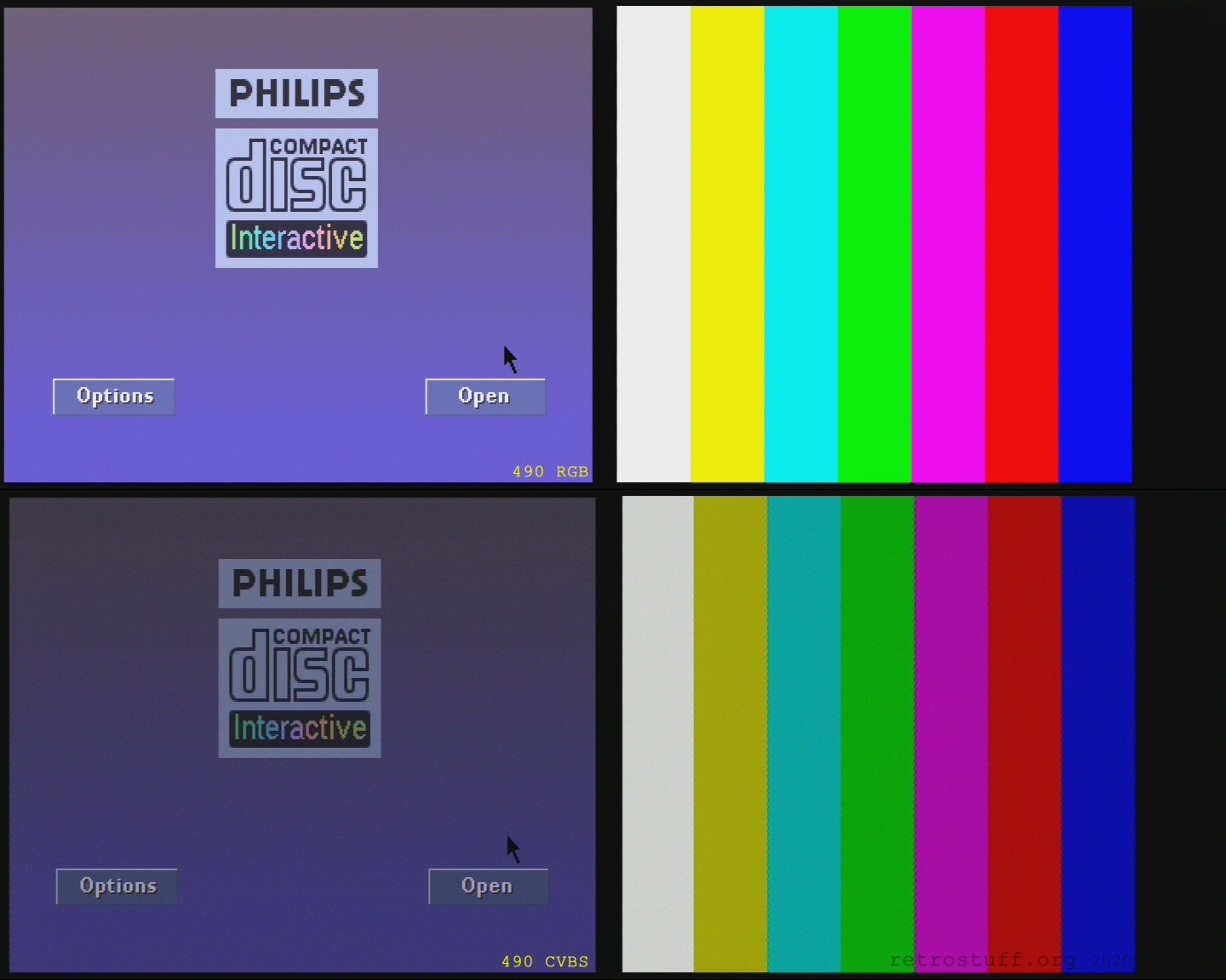
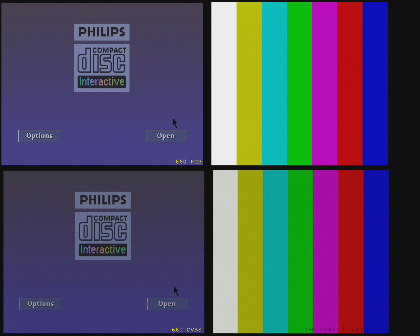
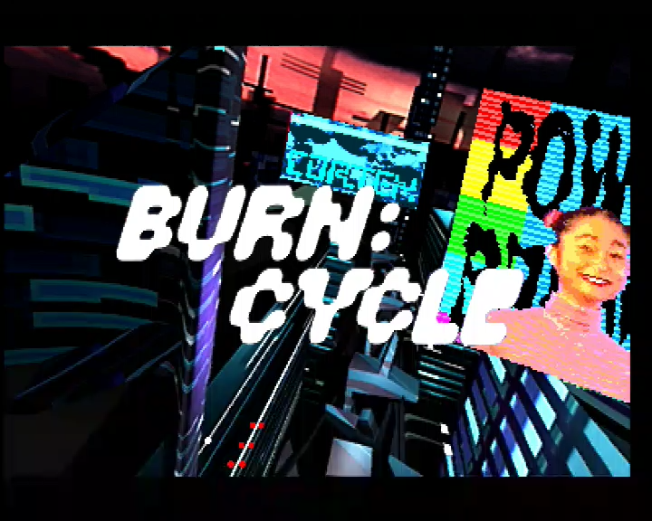
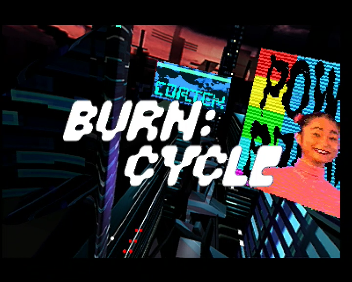
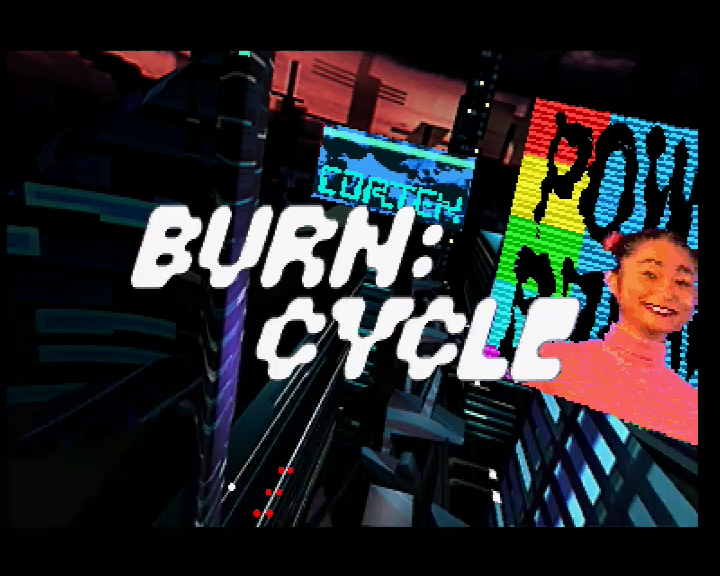
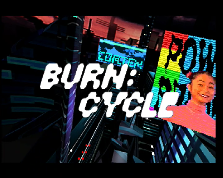
When I posted the first results, Interactive Dreams mentioned that the brighter output actually looks better than the original. But that is only the case while looking at the test image or while in the player shell (which is rather dim). When playing games, you will notice that the increased brightness removes details of the picture. Here are colourful screen grabs of the intro animation of Burn:Cycle (490 on the left and 660 on the right):
Good RGB
For the video signals we need 22 0805 SMS resistors, four BC 548B NPN transistors and four EMI suppression filters. Philips used resistors with 1 and 5 % tolerance (see components list), but I went for 1 % only because the cost is not a factor anymore.
This is a map of all needed components for RGB and CVBS. Use it as a guide to place the components, along with the service manual. Pay special attention to the resistors 3162, 3163, 3182, 3183, 3189 and 3190: These are wrong in the service manual (820 Ω, 1 %). The correct value for all of them is 510 Ω, 1 %.
To figure out the correct values, I compared several RGB SCART-enabled Mono III and Mono IV mainboards with the corresponding service manuals. In all manuals, the signals red, green, blue and CVBS were connected to GND with two 820 Ω resistors in parallel. On the mainboards, however, the signals red, green and blue were connected to GND with two 510 Ω resistors. CVBS matched the service manual.
All I had to do was to remove the six wrong resistors and add the correct 510 Ω resistors. You can see the better result immediately. For comparison, I added the pictures from above to the gallery.
If you look closely, then you will notice that the colour bars of the 490 and 660 still don’t match; the good RGB output of the 490 is still a bit too bright. Is it? Let’s have a look at the RGB output of two CD-i players with Mono III mainboard (220/60 and 210/40):
The RGB output of the 220/60 is an almost perfect match to the good 490 output. The 210/40 is a little bit darker. I will have to dig deeper into this topic in time, but this will be handled in another article.

Audio
Four 0805 resistors connect the analog audio section to the analog video section. There, two EMI suppression filters connect the signals to the SCART socket.
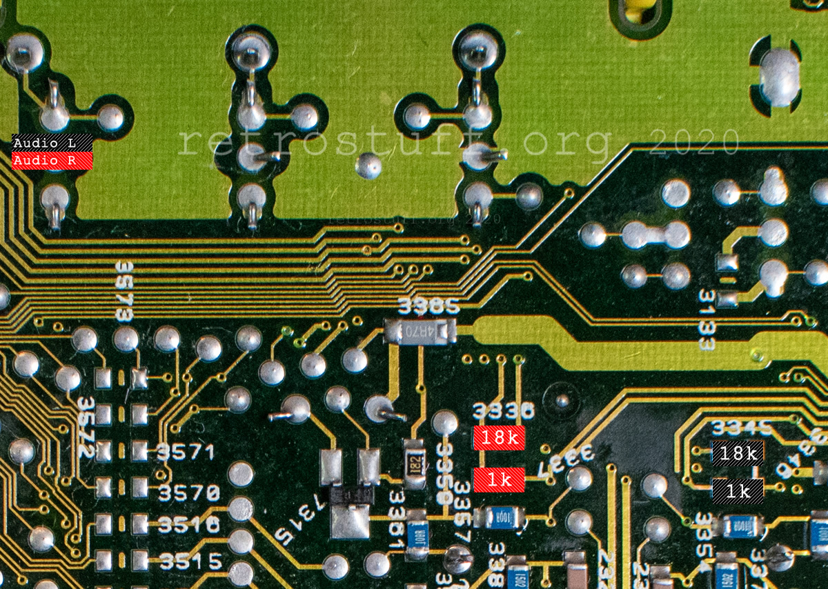
This is a map of all needed components for left and right audio. Use it as a guide to place the components, along with the service manual.

Switching signals
Switching signals indicate the type and aspect ratio of the video signal:
Switch on SCART pin 8 tells the TV that there is no signal (0 – 2 V) and switches it back to the previous input or it indicates the aspect ratio – widescreen 16:9 (4,5 – 7 V) and normal 4:3 (9,5 – 12 V). Almost all TVs have dedicated buttons for these functions (input select and aspect ratio).
Blanking on SCART pin 16 tells the TV if the signal is composite video (0 – 0,4 V) or RGB video (1 – 3 V). This very important because many TVs don’t have a button or menu option to switch the signal type manually.
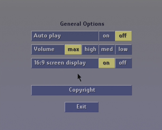
Philips CD-i players control the switching signals with the signals ASPRAT! (16:9 screen display on/off in the General Options menu) and CDTV! (CDI/TV button on the remote control). There is some confusion about the 16:9 menu option because it doesn’t seem to do anything at all. That is partially true because only very few applications support this feature and the format switching is only done by a TV that supports it. For more information, read chapter 3.13.3 of the CD-i FAQ 2020.
470 and 490 usually don’t have the 16:9 menu option. There is, however, an early 490 system ROM R1.2 with that option.
The following table shows the signal levels that I measured on CD-i players with Mono III and Mono IV mainboards (TP = test point, as indicated in the service manuals).
| Signal | Normal | CDI/TV button | 16:9 on | CDI/TV + 16:9 |
| ASPRAT! (before resistor 3135, TP269) | 0,01 | 0,01 | 4,95 – 5,10 | 4,94 – 5,10 |
| CDTV! (before resistor 3141) | 0,01 | 4,90 – 5,04 | 0,01 | 4,90 – 5,04 |
| Switch (SCART pin 8, TP245) | 11,24 | 0,06 – 0,07 | 5,48 – 6,19 | 0,06 – 0,07 |
| Blanking (SCART pin 16, TP192) | 1,84 – 2,18 | 0,15 – 0,16 | 1,84 – 2,18 | 0,15 – 0,16 |
Implementing the switching signals
This is a map of all needed components for both switching signals. Use it as a guide to place the components, along with the service manual (I took the values of other Mono III and Mono IV mainboards).
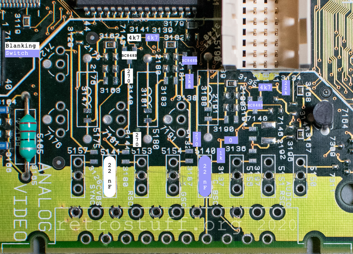
Again, the service manual has different values for some resistors and even misses two of them. I have tested the Blanking signal with both sets of resistors and both results are still within specification: 1,8 V according to a Mono IV board and 2,2 V according to the service manual / a Mono III board.
Another catch: Switch needs the +11 V line to generate the required voltages for SCART pin 8. Unfortunately, the power supply of the 470 and 490 CD-i players provides +5 V only. I still populated the required components to measure at least the ASPRAT! signal.
It’s up to you if you implement these signals, as they are not needed for RGB output. However, I strongly recommend implementing Blanking to keep compatibility with older TVs, as explained above.
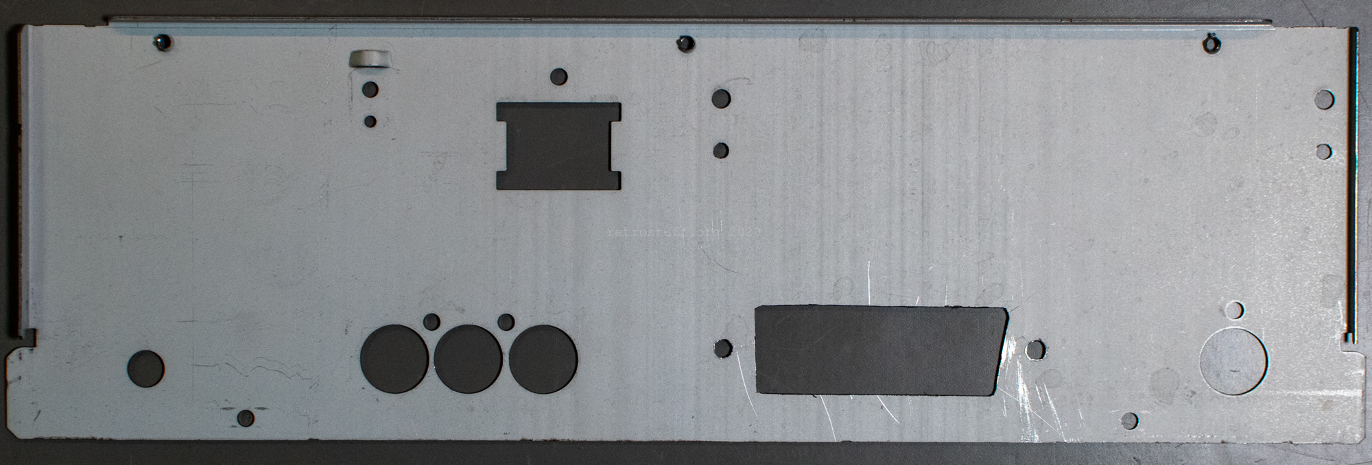
Modifying the case
If you made it here, then your mainboard probably looks like that. It won’t fit into the case anymore in that state. (Don’t mind the isopropyl alcohol, I’m just cleaning up.)
Cutting a hole into case turned out to be the hardest part of this modification, even when counting all the extra tests.
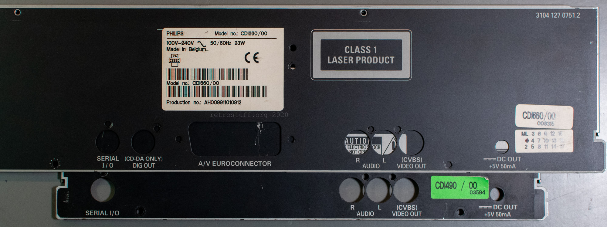
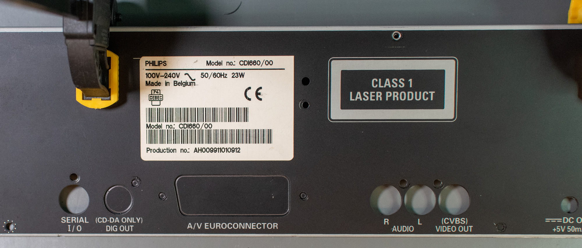
First, I disassembled a 660 player and used the back bezel as a template to draw the outline of the SCART socket (and also for the DO socket – maybe for another project?).
Then, I drilled several holes with step drills and cut the edges with a Dremel. Filing the rest into shape was the hardest part. The whole process took me several hours and produced a lot of fine metal dust. It’s one reason why I didn’t take any pictures during the process. This is the final result and it didn’t turn out too bad:
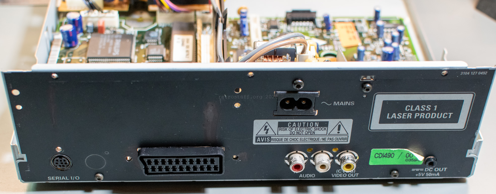
In case you’re interested in cutting holes into your 470 or 490 and don’t have a bigger CD-i player to use as a template, here’s the outline. Print it out and cut the holes, then attach it to your CD-i player.
Components
You will find four types of components in this list:
- A SCART socket.
- 0805 resistors, some of at least 1 % tolerance.
- T0-92 and SOT-23 transistors.
- Murata EMI suppression filters. The part numbers are in the notes column.
In the notes column you will also see if a resistor has to be removed first and resistors that were either missing or wrong in the service manuals.
| ID | Value | Package | Location | Signal | Notes |
|---|---|---|---|---|---|
| 1013 | 21 pins | SCART | D4 | All | Female SCART, right angle PCB mount |
| 3345 | 18 kΩ | 0805 | A4, back | Audio L | |
| 3346 | 1 kΩ | 0805 | A4, back | Audio L | |
| 5151 | 1 nF, 100 V | DSS306-55 | D4 | Audio L | DSS306-55Y5S102M100 |
| 3336 | 18 kΩ | 0805 | B4, back | Audio R | |
| 3337 | 1 kΩ | 0805 | B4, back | Audio R | |
| 5150 | 1 nF, 100 V | DSS306-55 | D4 | Audio R | DSS306-55Y5S102M100 |
| 3140 | 270 Ω | 0805 | E4 | Blanking | Wrong: 100 Ω |
| 3141 | 4,7 kΩ | 0805 | E4 | Blanking | |
| 3144 | 270 Ω | 0805 | E4 | Blanking | Missing in service manual |
| 5141 | 22 nF, 16 V | DSS306-55 | E4 | Blanking | DSS306-55F223Z16 |
| 7143 | BC 848B NPN | SOT-23 | E4 | Blanking | |
| 3188 | 0 Ω | 0805 | D4 | Blue | |
| 3189 | 510 Ω, 1 % | 0805 | D4 | Blue | Remove 470 Ω; wrong: 820 Ω |
| 3190 | 510 Ω, 1 % | 0805 | D4 | Blue | Wrong: 820 Ω |
| 3191 | 100 Ω | 0805 | D4, back | Blue | |
| 3193 | 150 Ω | 0805 | D4, back | Blue | |
| 3194 | 0 Ω | 0805 | D4 | Blue | |
| 3197 | 75 Ω, 1 % | 0805 | D4 | Blue | |
| 5156 | 220 pF, 100 V | DSS306-55 | D4 | Blue | DSS306-55Y5S221M100 |
| 7191 | BC 548B NPN | TO-92 | D4 | Blue | |
| 3127 | 100 Ω | 0805 | E4, back | CVBS | |
| 3128 | 75 Ω, 1 % | 0805 | E4 | CVBS | |
| 3129 | 150 Ω | 0805 | E4 | CVBS | |
| 5157 | 220 pF, 100 V | DSS306-55 | E4 | CVBS | DSS306-55Y5S221M100 |
| 7127 | BC 548B NPN | TO-92 | E4 | CVBS | |
| 3181 | 0 Ω | 0805 | E4 | Green | |
| 3182 | 510 Ω, 1 % | 0805 | D4 | Green | Remove 470 Ω; wrong: 820 Ω |
| 3183 | 510 Ω, 1 % | 0805 | D4 | Green | Wrong: 820 Ω |
| 3184 | 100 Ω | 0805 | E4, back | Green | |
| 3186 | 150 Ω | 0805 | E4, back | Green | |
| 3187 | 75 Ω, 1 % | 0805 | D4 | Green | |
| 5154 | 220 pF, 100 V | DSS306-55 | D4 | Green | DSS306-55Y5S221M100 |
| 7181 | BC 548B NPN | TO-92 | E4 | Green | |
| 3147 | 0 Ω | 0805 | E4 | Red | |
| 3149 | 100 Ω | 0805 | E4, back | Red | |
| 3150 | 150 Ω | 0805 | E4, back | Red | |
| 3162 | 510 Ω, 1 % | 0805 | E4 | Red | Remove 470 Ω; wrong: 820 Ω |
| 3163 | 510 Ω, 1 % | 0805 | E4 | Red | Wrong: 820 Ω |
| 3180 | 75 Ω, 1 % | 0805 | E4 | Red | |
| 5153 | 220 pF, 100 V | DSS306-55 | E4 | Red | DSS306-55Y5S221M100 |
| 7176 | BC 548B NPN | TO-92 | E4 | Red | |
| 3161 | 1 kΩ | 0805 | E3 | RGBout | Remove 3171 from E3 (back) |
| 3132 | 1,8 kΩ | 0805 | D4 | Switch | Missing in service manual |
| 3134 | 22 kΩ | 0805 | D4 | Switch | |
| 3135 | 4,7 kΩ | 0805 | D4 | Switch | |
| 3136 | 0 Ω | 0805 | D4 | Switch | Wrong: 300 Ω |
| 3137 | 1 kΩ | 0805 | D4 | Switch | Wrong: 300 Ω |
| 3138 | 1,8 kΩ | 0805 | D4 | Switch | Wrong: 680 Ω |
| 3139 | 4,7 kΩ | 0805 | E4 | Switch | |
| 5140 | 22 nF, 16 V | DSS306-55 | D4 | Switch | DSS306-55F223Z16 |
| 7140 | BC 848B NPN | SOT-23 | D4 | Switch | |
| 7141 | BC 848B NPN | SOT-23 | D4 | Switch |
I have the 660 Pro which has already RGB and (auto) PAL/NTSC. Unfortunately it does not output MultiChannel Digital (Coax S/PDIF) audio from VCD / CD-I discs. Are there some instructions available how to modify?
What do you mean by (auto) PAL/NTSC?
No, DO is directly connected to the servo/CD decoder and only outputs stereo CDDA. To have digital audio from CD-i/VCD, you might want to investigate if the signal can be intercepted before it enters the DAC. (Digital multi-channel audio isn’t supported at all by CD-i players. Dolby Surround is transported in the stereo audio.)
Any plans to sell this?
Sorry, not in the near future. The experiments with this player are not over.
Hi! Thanks alot for this tutorial.
Just completed it, unfortunately the image looks kinda fuzzy : https://ibb.co/pJZpr5x (i took the photo in B&W).
I didn’t notice anything suspicious except the EMI filters that do not all have the right value (they’re all 22nF), do you think it could be the cause?
When i’m done with this, i’m going to change the Timekeeper, i may go for the 32k upgrade!
Hi and thanks for your feedback!
Can you tell me more about your equipment and take a picture of the modification?
(e.g. full CD-i player model/version, SCART cable, TV and if you have converter/scaler in the chain)
I haven’t checked what happens with wrong EMI filters, but you could try to remove them and bridge the outer contacts when in doubt.
Thanks for the quick answer! I will try that and take pictures this weekend, i’m not at home right now.
It’s a PAL 470, connected directly to an LG flatscreen with a regular unbranded SCART, but both the TV and the cable gave pretty good result swith other RGB consoles.
Hi,
I removed the EMI filters on composite video, R, G and B, and now it looks good! Looks like that was the issue.
I will search for the right filters, but in the meantime there doesn’t seem to have too much interference.
Hi,
That’s great, it will be an easy fix!
Let me know if your run into any problems with the other modifications.