
A collection of technical information to assist in troubleshooting and the repair of Pippin Atmark consoles. You can use it side by side with the disassembly guide in my Pippin Atmark PA-82001-S Monitoring Unit article from 2019.
You will find details about the FFC of the control buttons, the Matsushita CR-504-L optical disc drive and the VOLTEK SPEC7188B power supply unit. The information applies to both “monitoring” and retail units.
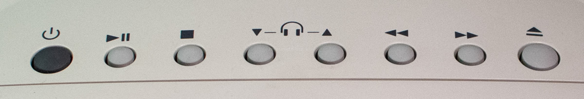
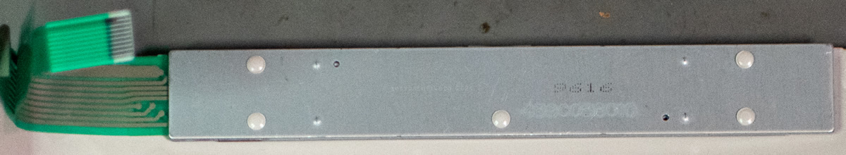
Control buttons FFC
These are the control buttons on the top of the Pippin and what they look like on the back. When you open the case of a Pippin, pay special attention to the FFC (flexible flat cable). Otherwise you could damage the control buttons, the FFC or even the ZIF connector on the mainboard.
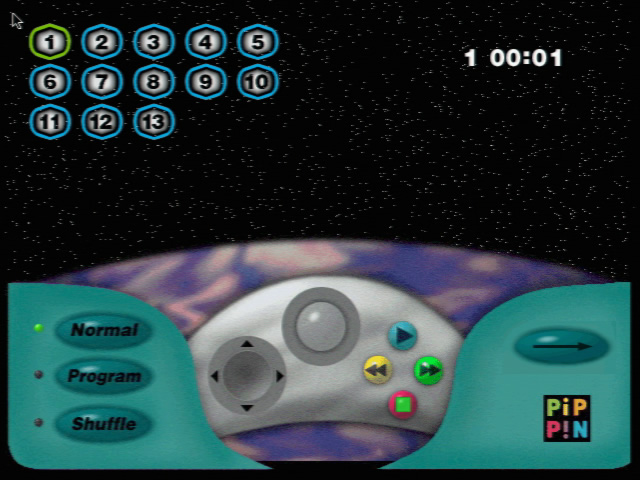
In the worst case that something happened, or if you simply want to switch on or control the Pippin without the control buttons, you will find the pinout here:
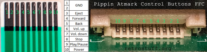
Each conductor 3-10 corresponds to one of the buttons and 1+2 are the return line (GND). If you want to switch on the Pippin, you must briefly short the two outer conductors on the connector. You can of course use any other GND, such as the metal case.
If you have disassembled the Pippin further, then there is another easier way to switch it on. We will come to this later when we look at the power supply.
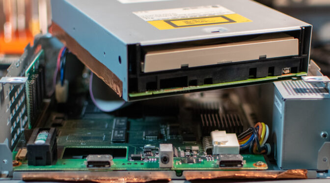
Matsushita CR-504-L
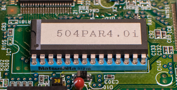
The Pippin CD-ROM drive is a Matsushita CR-504-L, set to SCSI ID 3, which identifies itself as MATSHITA CD-ROM CR-8005A 4.0i.
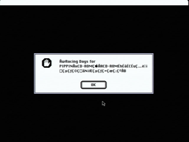
You could replace it with other SCSI CD-ROM or even DVD-ROM drives, but then you will lose two functions: the eject button on the top of the console will not open the tray and audio CDs will no longer be recognised, resulting in the loss of the audio CD player interface. This also affects the title Racing Days as it contains CDDA tracks for the background music. Racing Days therefore refuses to start and displays a cryptic error message.
Another option is to use a SCSI device emulator such as BlueSCSI or SCSI2SD with the following settings to emulate the original ODD. However, since these emulators do not have a CDDA connector, you will not hear any audio tracks (but hey, the error is gone).
Vendor = "MATSHITA"
Product = "CD-ROM CR-8005A"
Version = "4.0i"
If these two features are important to you then it is crucial to keep the ODD in a good working order and/or have a replacement like the AppleCD 600i on hand: this can either be a Matsushita CR-504-K / -L (identical), CR-504-J (untested) or a Sony CDU75S-25. A Sony ODD disguised as “CR 504” was found by Cobra! and successfully tested with the Pippin, even if it doesn’t fit perfectly. It identifies itself as SONY CD-ROM CDU-8005 1.0j.
Disassembly
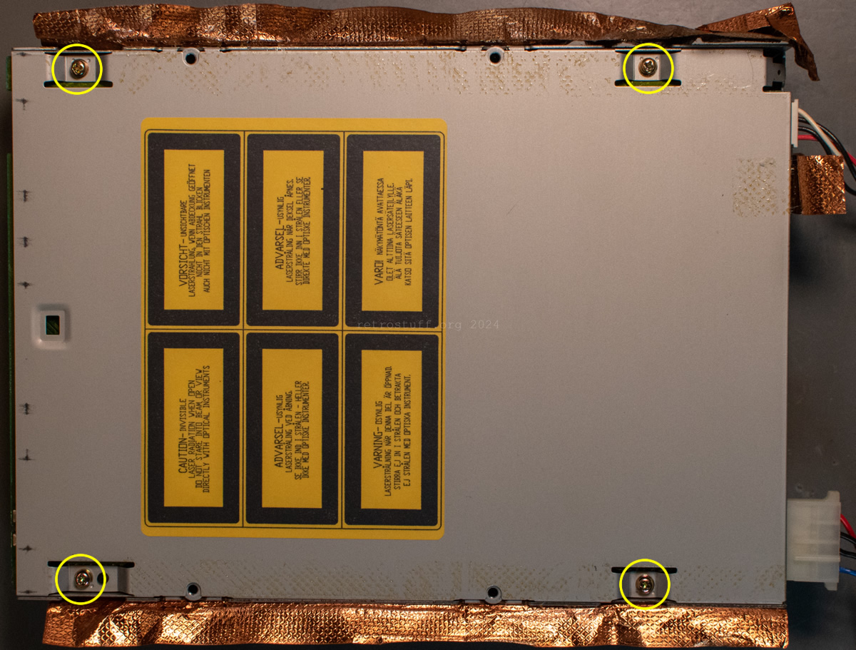
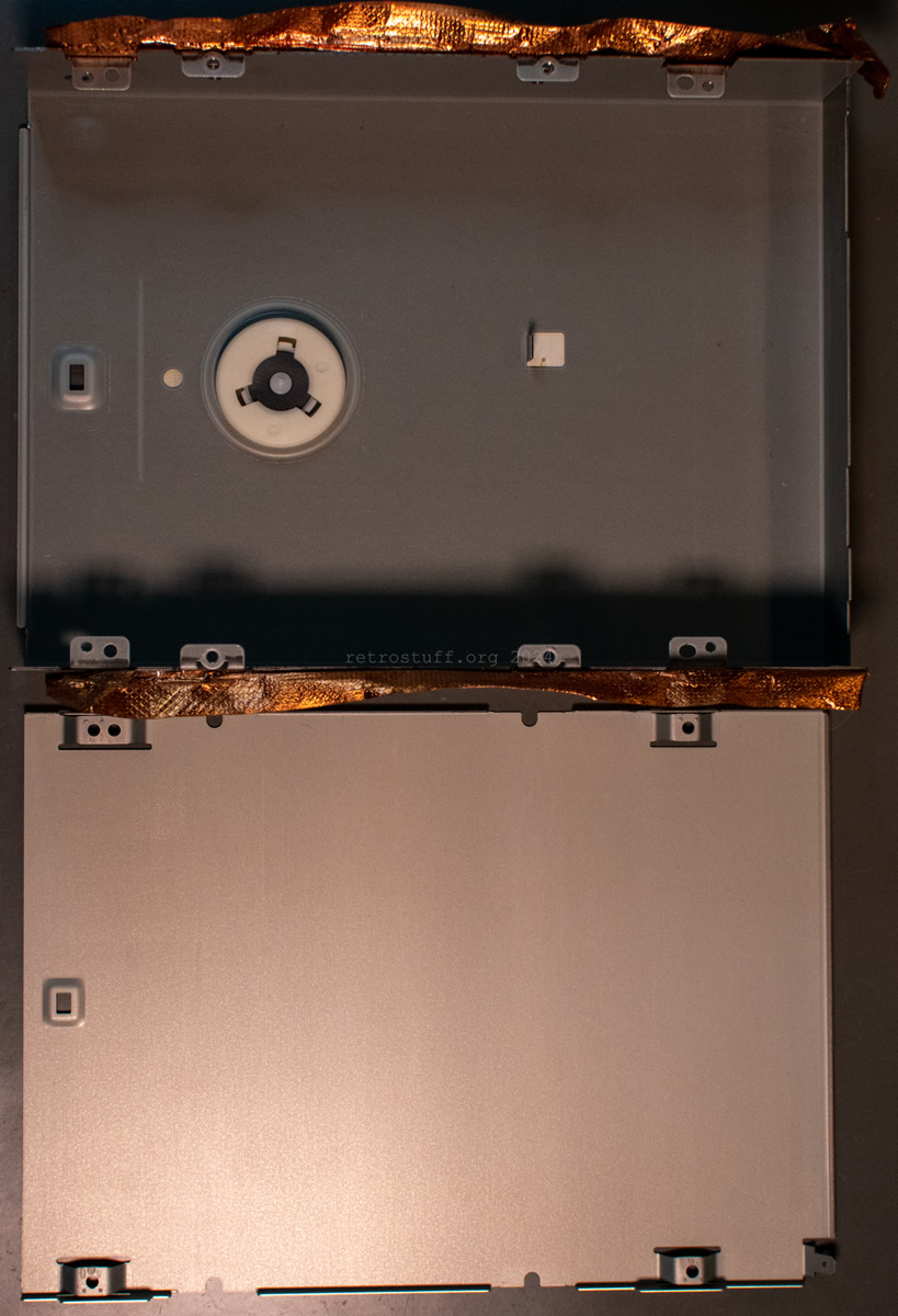
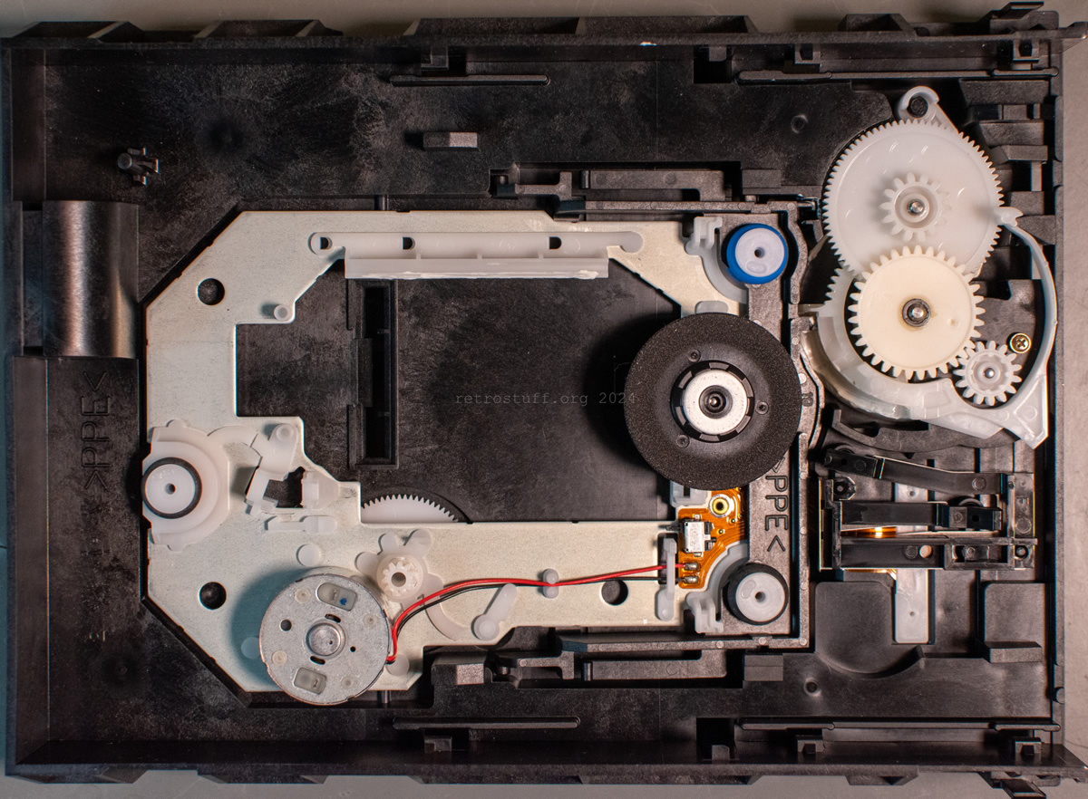
The Matsushita CR-504-L (and -K) must be disassembled from the bottom side (ignore the copper foil tape on the photos, the retail units do not have this). Start by removing the four JIS screws and the bottom cover:
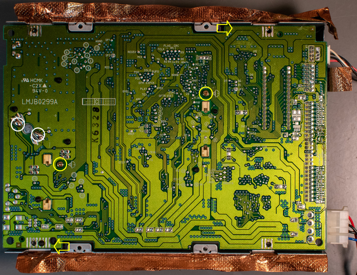
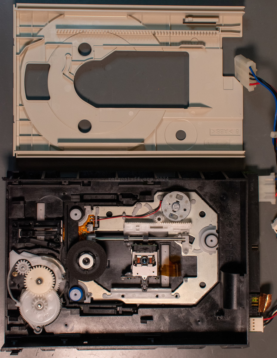
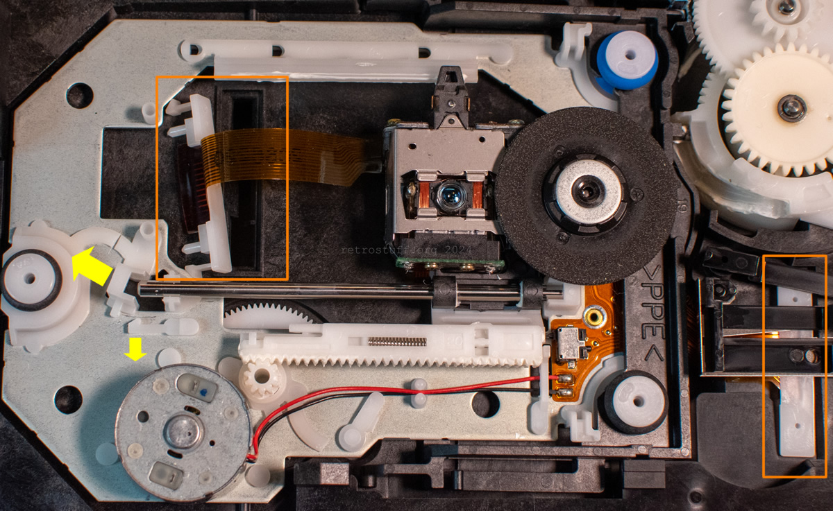
Then, bend the two barely visible black plastic tabs in the direction indicated by the yellow arrows and remove the entire mechanism with the attached PCB from the top case. The photo also shows important points for the later removal of the PCB: two JIS screws (yellow circles) and two soldering points of the tray motor (white circles).
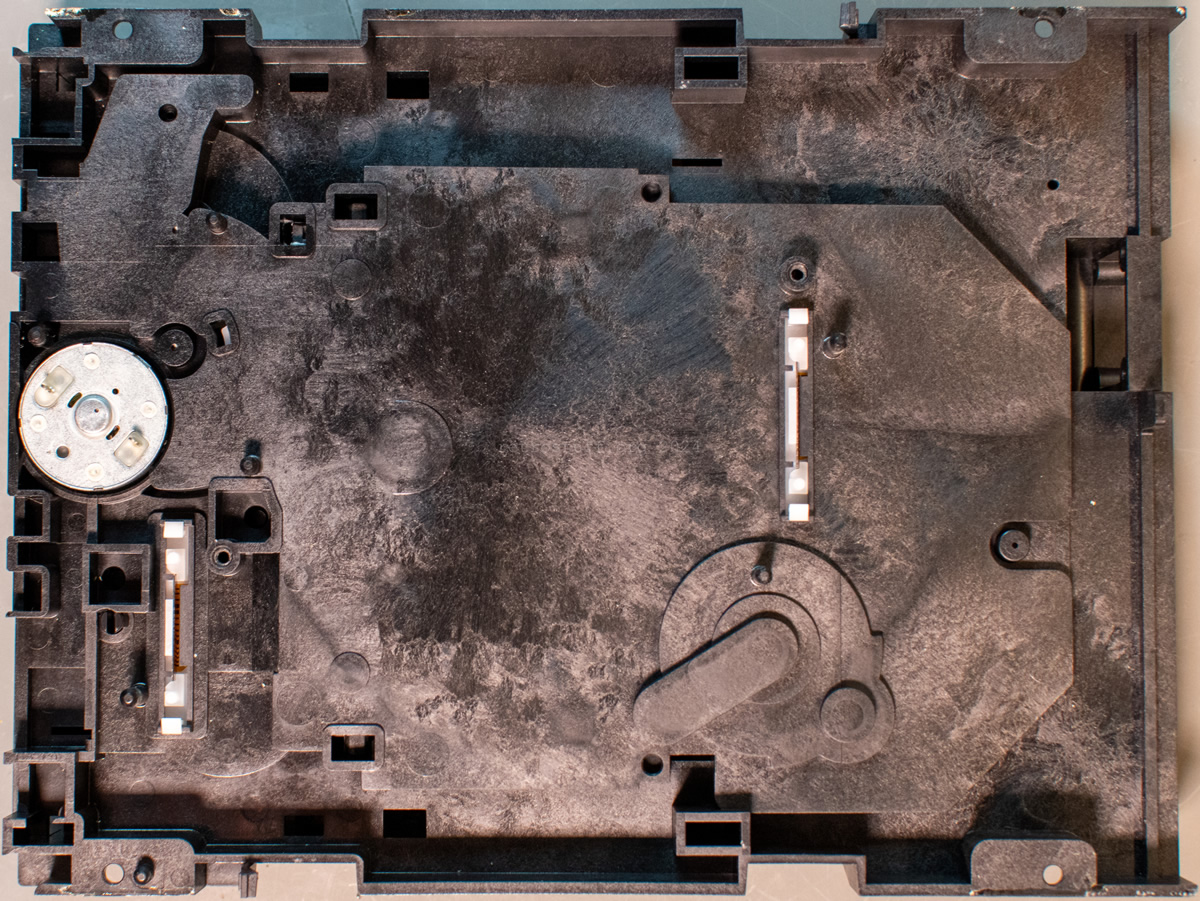
One last look at the case parts before we turn our attention to the inner components. We can see that the clamper is attached to the top case.
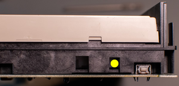
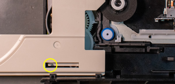
Now open the disc tray by pressing a blunt tool into the hole marked with a yellow dot. Pull the tray out as far as it will go and then unlock it by pulling the plastic tab upwards with pliers or tweezers (yellow circle). The tray can then be removed completely.
Next, remove the PCB as described above.
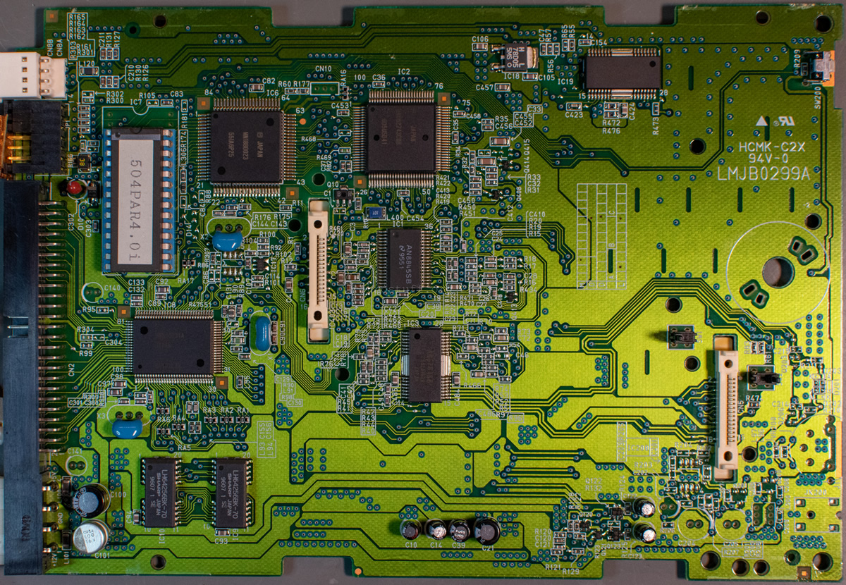
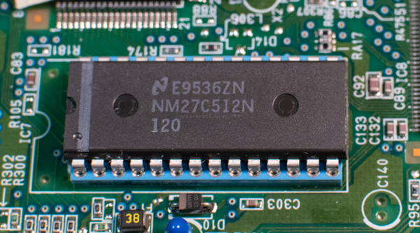
A National NM27C512N 524,288-Bit (64K x 8) High Performance CMOS EPROM chip (N = plastic OTP DIP package) contains the 504PAR4.0i firmware. Nice touch: a Matsushita brand precision socket.
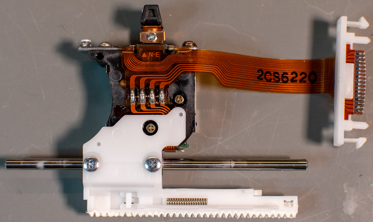
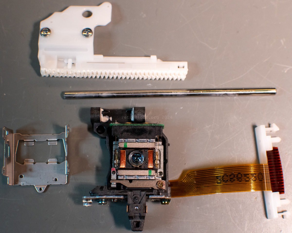
Laser sledge
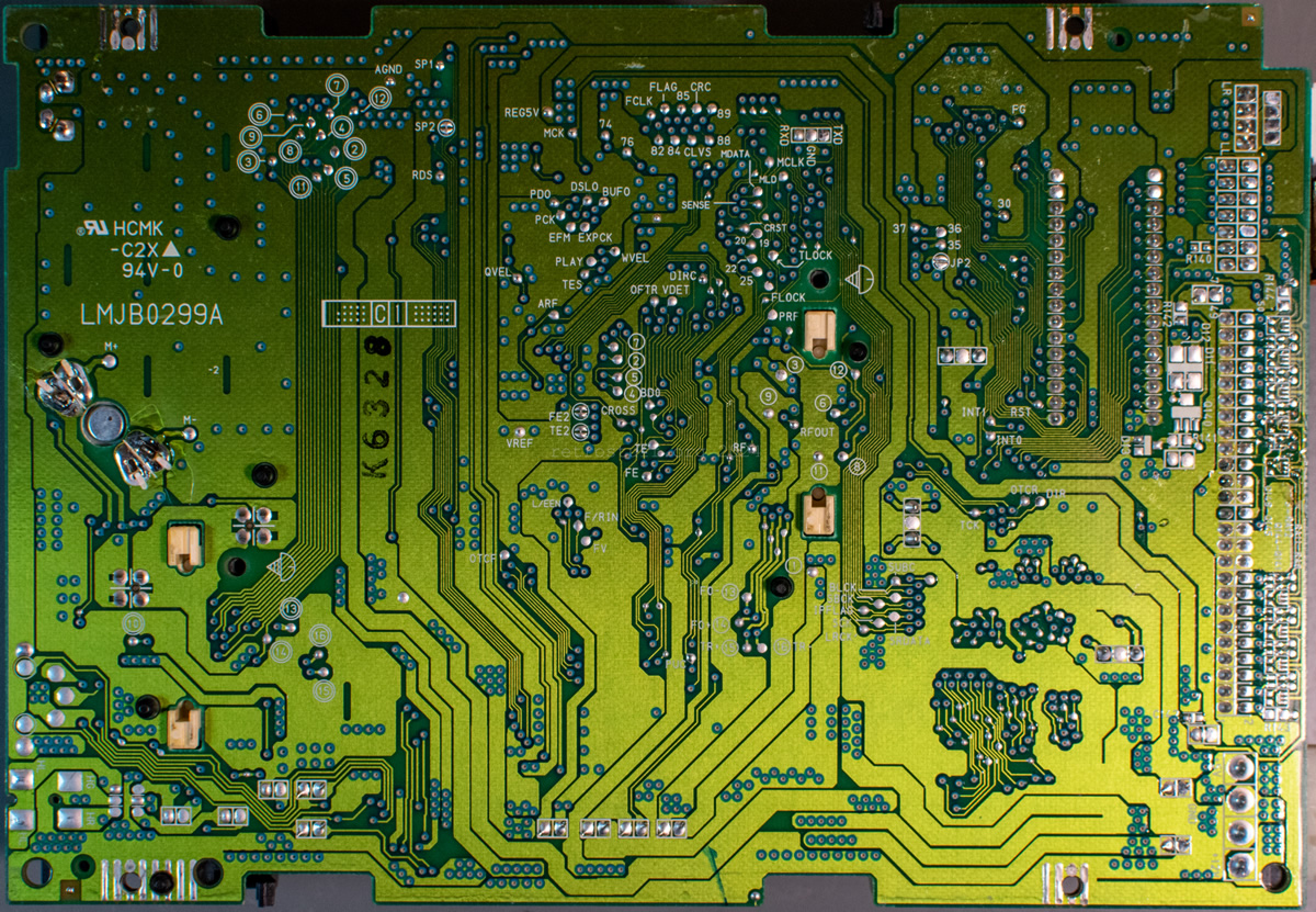
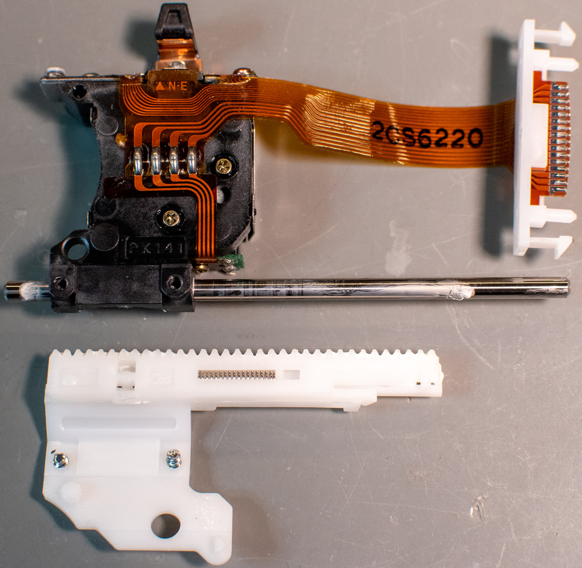
To access and remove the laser sledge, you will need to unlock the latch that keeps the steel rod in place. To do this, pull the small plastic hook slightly downwards and then turn the latch to the left/upwards. Also pay attention to the plastic holders of the FFCs (orange-coloured rectangles) – these match the connectors on the PCB. Before reattaching the PCB later on, make sure that both are firmly seated in their holes, as shown in the photo from the back.
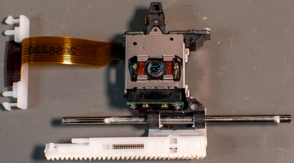
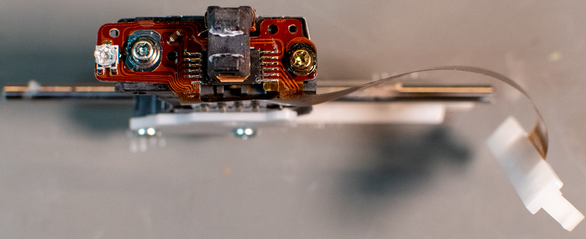
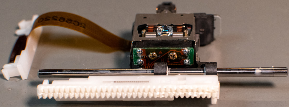
And this brings us to the most important part of the optical drive: the laser sledge. So far it has not been possible to identify it. There are only two markings: PK141 and 2CS6220, neither of which lead to any search results. Until a suitable replacement is found, enjoy the photos from all sides:
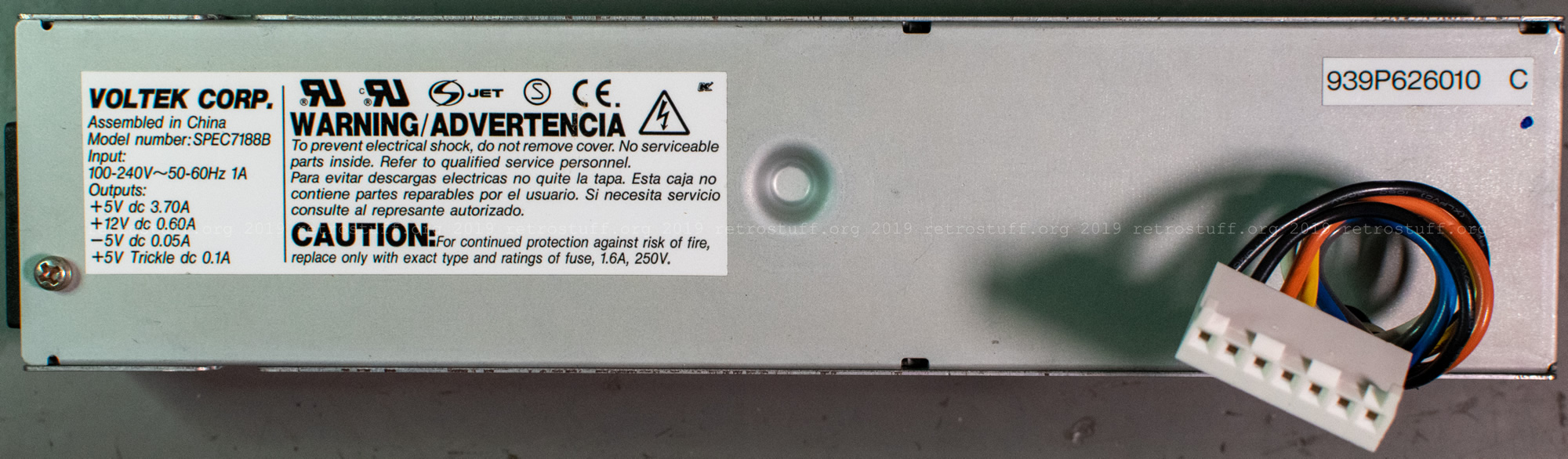
VOLTEK SPEC7188B
Although there is no datasheet for the SPEC7188B switching power supply from VOLTEK CORP., you will find enough information on the detailed PCB markings and the label.
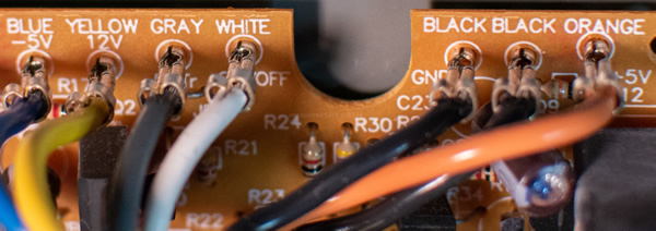
For your reference, this is the pinout of the connector:
| Conductor | PCB Marking | Label |
| 1 black | BLACK GND | |
| 2 black | BLACK GND | |
| 3 orange | ORANGE +5V | +5 V dc 3,70 A |
| 4 yellow | YELLOW 12V | +12 V dc 0,60 A |
| 5 white | WHITE ON/OFF | |
| 6 blue | BLUE -5V | -5 V dc 0,05 A |
| 7 grey | GRAY 5VTr | +5 V Trickle dc 0,1 A |
To switch it on, connect conductors 5 and 7 either just briefly (if it is connected to the Pippin mainboard!) or permanently (if it is not connected to the Pippin mainboard!).
Components
Some important components of the PSU:
- A T1.6H250V 5 x 20 mm glass fuse (1,6 A slow-blow / high breaking capacity / 250 V).
- 13 electrolytic capacitors from Nippon Chemi-Con. All capacitors in the power supply of my Pippin are still within their specifications. Should they need to be replaced at some point, the specifications and links to the data sheets are in the following table:
| ID | F | V | Size mm | Pitch | Series |
|---|---|---|---|---|---|
| C2 | 150 µ | 400 | 30 x 25 | 10 | KMM |
| C6 | 100 µ | 16 | 5 x 11 | 2* | KMG |
| C9 | 2200 µ | 10 | 12,5 x 25 | 5 | SXE |
| C10 | 2200 µ | 10 | 12,5 x 25 | 5 | SXE |
| C11 | 2200 µ | 10 | 12,5 x 25 | 5 | SXE |
| C12 | 470 µ | 25 | 10 x 20 | 5 | SXE |
| C13 | 100 µ | 16 | 5 x 11 | 2* | KMG |
| C16 | 2,2 µ | 50 | 5 x 11 | 2* | KME |
| C17 | 220 µ | 25 | 8 x 15 | 3,5 | SXE |
| C18 | 4700 µ | 10 | 12,5 x 25 | 5 | KMG |
| C19 | 100 µ | 16 | 5 x 11 | 2* | KMG |
| C23 | 2,2 µ | 50 | 5 x 11 | 2* | KME |
| C25 | 220 µ | 25 | 8 x 15 | 3,5 | SXE |
2 thoughts on “Pippin Atmark Troubleshooting and Repair Information”