2018 will be a great year for the PC Engine. Terraonion, the maker of the NEOSD cartridge, has announced the Super SD System 3 add-on.
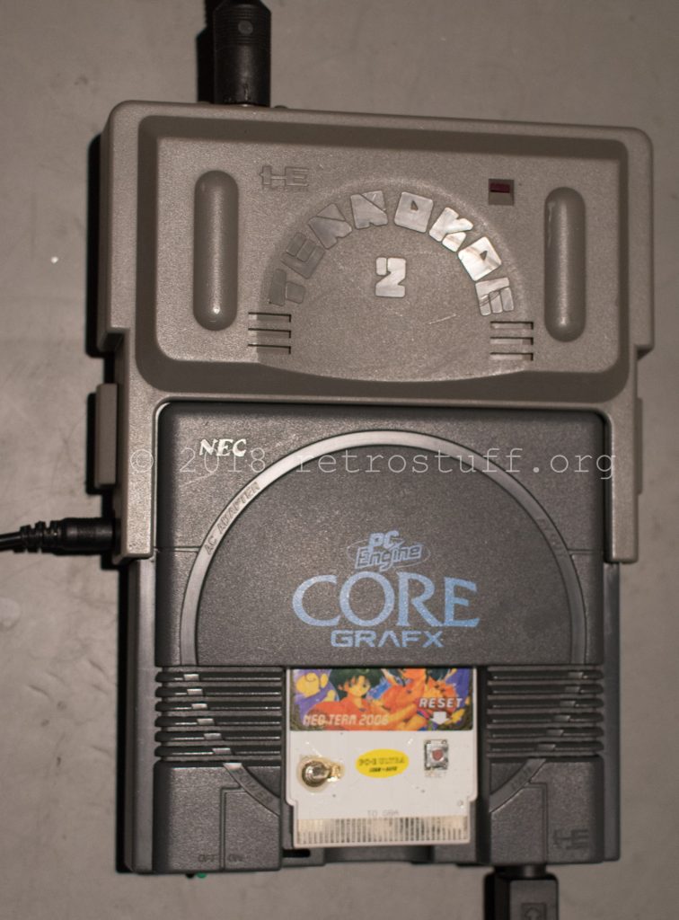
Unfortunately I won’t be able to use it with my Duo-RX and GT, and the SuperGrafx is too bulky and ugly to take it out for gaming. I ordered a cheap CoreGrafx from Yahoo! Japan Auctions which came with a Tennokoe 2 backup memory device attached to the expansion connector.
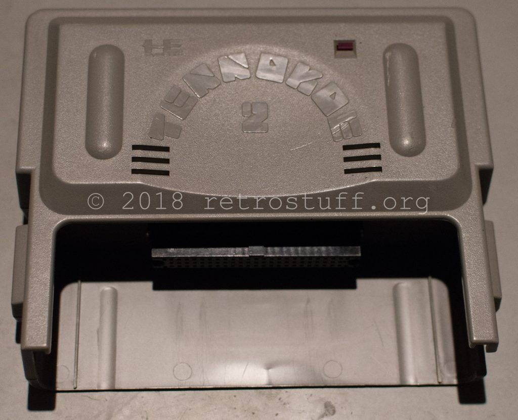
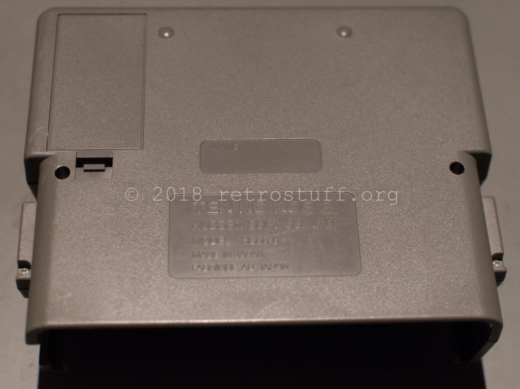
This device needs same cleaning:
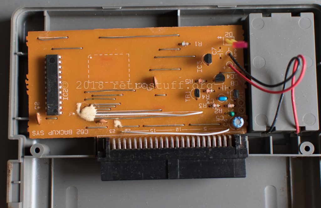
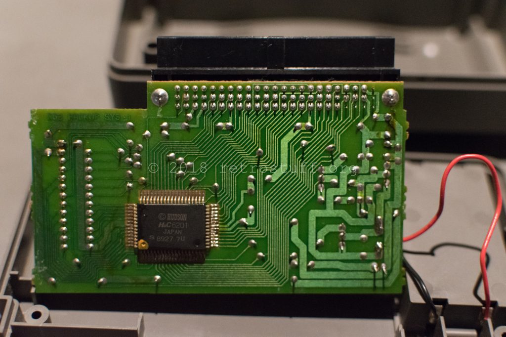
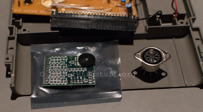
I really don’t need a memory device right now, but I could use an external RGB connector, because my SuperGrafx also suffers from bad RGB modding by its previous owner. The general purpose AV-Driver by Tim Worthington, a 8-pin DIN socket and some wire is all that I need. I ordered a couple of those drivers for my Neo Geo MVS and initially planned to put one of them into the SuperGrafx, but this external solution is more convenient.
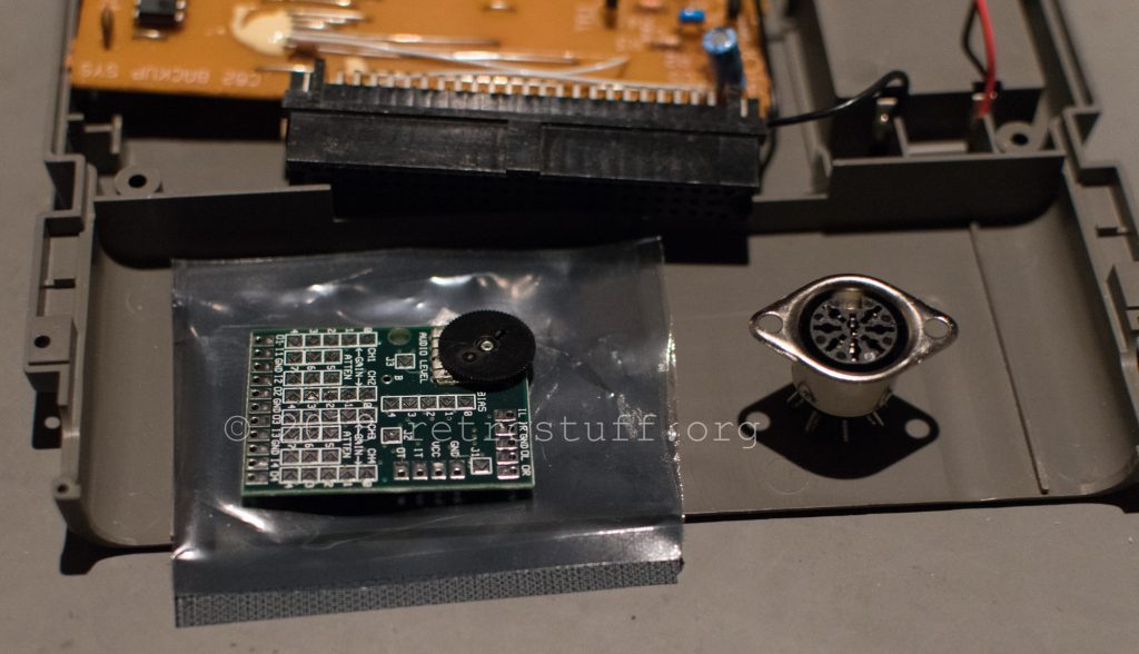
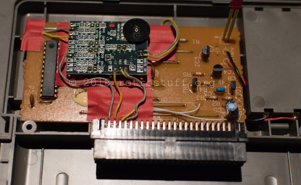
This forum post describes how to set up the AV-Driver for PC Engine: Close jumpers J2 (75 ohm sync output) and also 1 and 2 for each channel and bias (boost video output). Then connect it to the expansion port connector of the Tennokoe 2 and the DIN socket, the correct solder points and examples are being shown here and here.
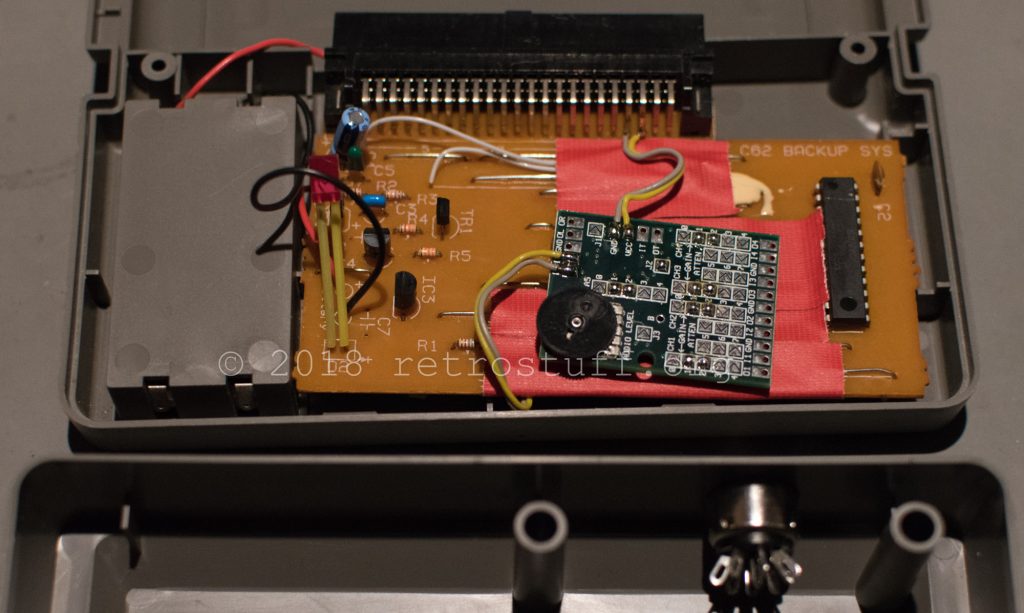
I tapped Ground, +5V, Sync and Blue right next to it at the connector to keep the wires as short as possible.
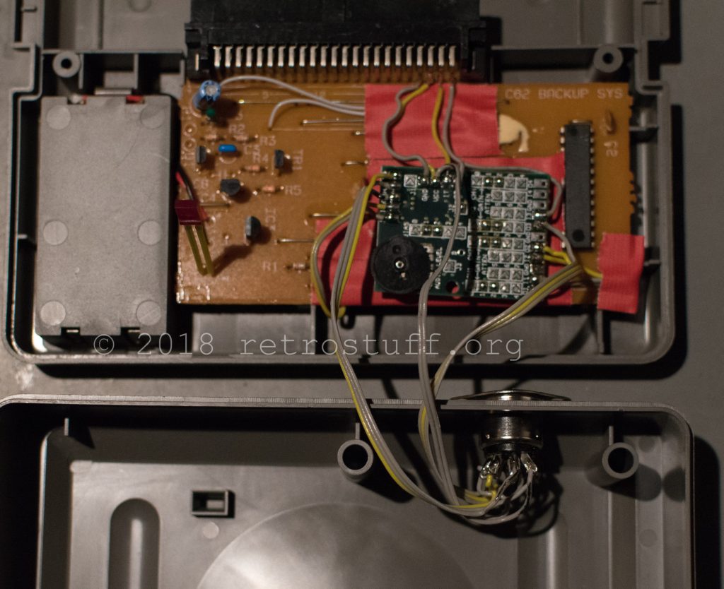
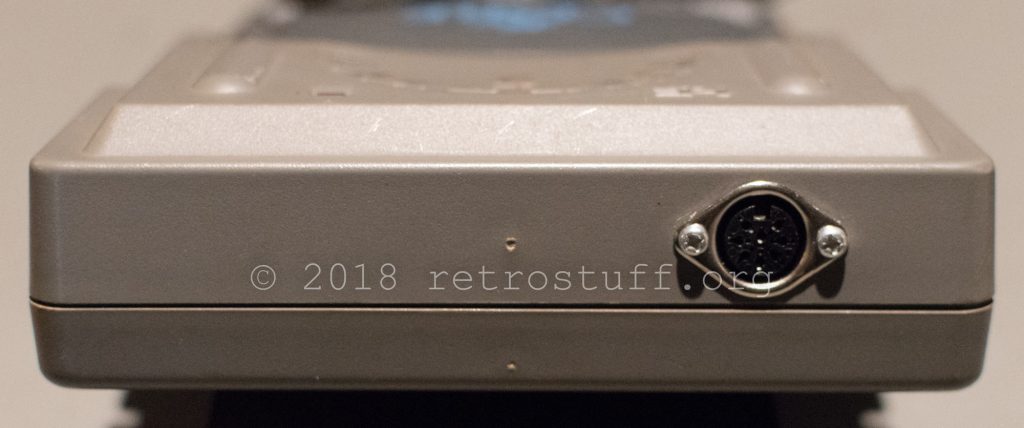
DIN socket isolated and secured to the casing:
Ready to play some HuCards in RGB quality:

I tried modding this RGB output, but only with mono audio output, not stero audio output. How to fix it?
Thanks.
Check the pinout of the expansion port on this page: http://www.pcenginefans.com/forum/index.php?topic=23169.0
The audio channels are on C1 and A1.
Thanks. Any Audio amp circuit should be added on it? just connect the pin C1 and A1 to socket is ok?
It will probably work, but I didn’t try it. I’ve used the AV-Driver which takes care of both audio and video.
Great work. Can you advise which pin on the Tennokoe 2 pcb is for composite video please? I’m struggling to find a pin out diagram for it to effect a mod repair. Thanks.
I used the solder points of the expansion connector. Check the links above and in the article for the pinout.