
The aim of this article is to compile a comprehensive documentation of all known power supply units for Philips CD-i players. It is a work in progress and will be updated with new information at regular intervals. I welcome feedback, especially if you discover an error or can contribute additional information.
Frequently asked questions concern the operational safety of a model in different countries and the location of fuses. To answer these questions accurately, you need to know the specific built-in or external power supply associated with the model, version and revision of the player. The grouping by mainboard/hardware generation provides a clear overview, as already shown in the article Modifications for Philips CD-i players.
The documentation of the fuses in the Mono III and IV generations began years ago with the article Philips CD-i Mono III / IV Fuses, and it was always the plan to summarise it in a more comprehensive article covering all generations.
This article now follows that approach and presents specifications, information on fuses, compatibility and possible modifications. It summarises all relevant data from the previously mentioned articles.
List of power supply units sorted by manufacturer and mainboard / hardware generation:
- Philips
- Maxi MMC / Mini MMC
- Mini MMC-based (portable players)
- 22ER9151
- Mono I / Mono II
- Mono III / Mono III-based / Roboco
- Mono IV
- GoldStar / LG
- Midi-size players
- Portable players
- Kyocera
- Sony
General information and warning
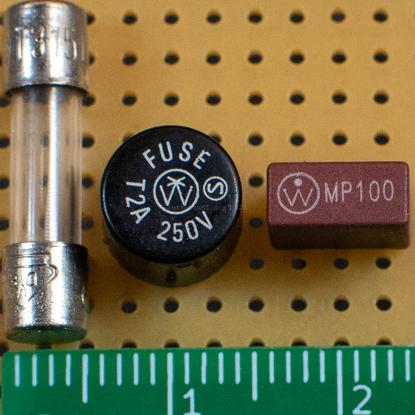
Some fuse types and identification methods:
- Guide to labelling 5 x 20 mm miniature glass fuses.
For example, the designation “T1.0A L 250V” indicates a slow-blow (time-delay) 1 A / 250 V glass fuse with a low breaking capacity. - Wickmann / Littelfuse 372 series TR5 fuses (250 V).
For example, the designation “T2A 250V” indicates a slow-blow (time-delay) 2 A / 250 V TR5 fuse. - Wickmann / Littelfuse 398 series TE5 fuses (65 V).
For example, the designation “MP400” indicates a 4 A / 65 V TE5 fuse.
Please note the following warning before disassembling anything:
Always unplug the power cord and leave the power switch in the ‘on’ position for some time before inspecting a power supply unit.
I have marked the large filter capacitors, such as 2103, with a warning sign in the photos, as they can cause an electric shock if they are not discharged properly.
If you need to measure something while the PSU is switched on, make sure it is safe, stay away from the live area and do not operate it without a load.
I accept no liability if you modify a power supply unit in such a way that it no longer complies with the regulations in your country and may even result in personal injury or damage to property.
Maxi MMC / Mini MMC
These switched-mode power supply units are multi-voltage capable, but only professional and authoring players have a voltage selector. Consumer players have a fixed voltage.
[Further details will follow.]
Mini MMC-based (portable players)
22ER9151
External power supply unit for the CDI 350 and 360 (Mini MMC-based portable players by Marantz/Philips Japan).
[Further details will follow.]
Mono I / Mono II
Power supply units for the Mono I and Mono II generations utilize a big transformer that is usually only designed for a single region.
TL;DR: You will most likely need a step-up or step-down converter when importing one of these models to another region of the world.
Mono I: 220/20/25/31/37/39 and 210/00/05/17 (200/17)
Mono II: 220/40/41/45/57 and 210/20/25/37 (200/37)
To keep things as simple as possible, I will refer only to the 220 models, versions and revisions. As a rule of thumb: for the corresponding 210 models (200 in the US) you must always subtract 20 from the numbers after the slash (e.g. 210/05 ≙ 220/25 and 200/17 ≙ 220/37). This is because the 220 series was launched earlier and initially featured a different hardware generation.
Transformer
As noted above, the transformers are generally designed for a single region only. The only exceptions are the EU/UK versions, which can be switched via a jumper on the power supply board. The service manual also mentions a multi-voltage PAL version /41, but it is not yet known whether this actually exists.
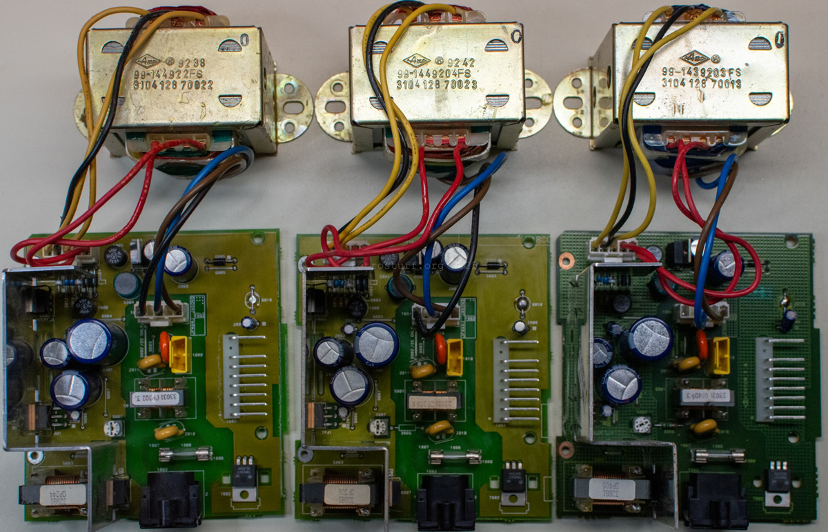
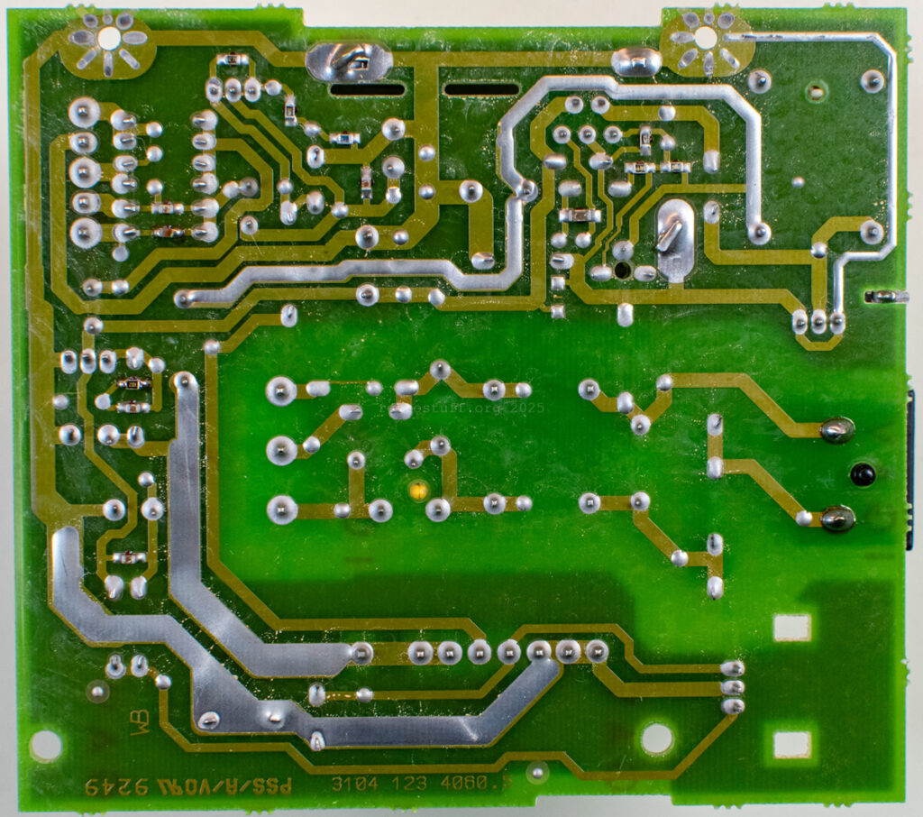
Bottom row: PCBs 3104 123 4060.4, 3104 123 4060.5 and 3104 123 4060.8
Known variants
- /20/25/39/40/45 (4822 146 31208, 3104 128 70022 and 3104 128 70023) – EU/UK version (220-230 V and 240 V / 50 Hz).
- /31 (4822 146 31209) – Japan version (100 V / 50-60 Hz).
- /37/57 (4822 146 31201, 3104 128 70013) – US version (120 V / 60 Hz).
- /41 (4822 146 31321) – Multi version (110 V, 127 V, 220-230 V, 240 V).
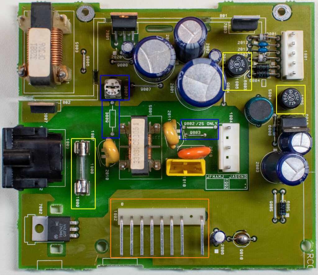
Power supply board 3104 123 4060
The power supply board is virtually identical across all known variants: it’s the 3104 123 4060 PCB in slightly different revisions and configurations.
Different jumpers and fuses are required depending on the region. Here is a table from the service manuals, which I have supplemented with my findings regarding resistor 3809 and power inlet 1803.
| /20/39/40 (EU) | /25/45 (UK) | /31 (Jp) | /37/57 (US) | /41 (Multi) | |
| Jumper | 9803 | 9802 | 9803 | 9803 | 9803 |
| 1808 | T315mA | T315mA | T800mA | T600mA | Conflicting information in the service manual |
| 3809 | ./. | ./. | ? | 10 MΩ | ? |
| 1803 | C8 | C8 | ? | C8P | ? |
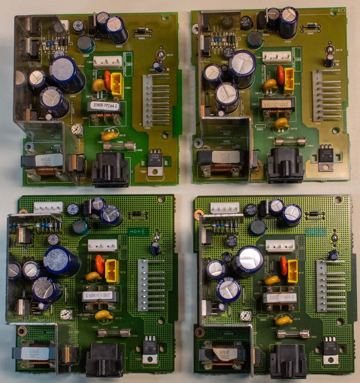
Bottom row: 3104 123 4060.8 (US) and 3104 123 4060.8 (EU)
Known variants
- /20/39 (3104 128 0136, PCB 3104 123 4060.4 and .5) – EU version (Mono I) with C8 inlet.
- /40 (3104 128 0280, PCB 3104 123 4060.8) – EU version (Mono II) with C8 inlet.
- /57 (3104 128 0249, PCB 3104 123 4060.8) – US version (Mono II) with polarised C8P inlet. Neutral (squared side) is connected to GND with resistor 3809 (10 MΩ, not documented in the service manual).
Technical data
Service Manual: Several are available, but CDI 220 (/40/41/45/57) is recommended as it is the most comprehensive and up-to-date version.
Input:
/20/39/40 – 220 – 230 V AC 50 Hz
/25/45 – 240 V AC 50 Hz
/31 – 100 V AC 50-60 Hz
/37/57 – 120 V AC 60 Hz
/41 – 110 V, 127 V, 220-230 V, 240 V AC 50-60 Hz
Output: +5 V / 3,5 A, -5 V / 400 mA, +25 V / 50 mA
Fuses
- Main 1809 – glass fuse (5 x 20 mm)
/20/25/39/40/45 – T500mA L 250V
/31 – T800mA
/37/57 – T600mA / T0,63 250B
/41 – ? (conflicting information in the service manual) - +5 V, +25 V 1805 – T2A 250V TR5 fuse
- -5 V 1806 – T1A 250V TR5 fuse
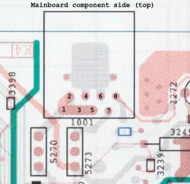
Pinout
| PSU Pin | Signal | MB Pin |
|---|---|---|
| 1802 Pin 1 | +5 V | MB 1001 Pin 1 |
| (no pin) | – | (no pin) |
| 1802 Pin 2 | +5 V | MB 1001 Pin 2 |
| 1802 Pin 3 | +5V | MB 1001 Pin 3 |
| 1802 Pin 4 | -5 V | MB 1001 Pin 4 |
| 1802 Pin 5 | +25 V | MB 1001 Pin 5 |
| 1802 Pin 6 | GND | MB 1001 Pin 6 |
| 1802 Pin 7 | GND | MB 1001 Pin 7 |
| 1802 Pin 8 | GND | MB 1001 Pin 8 |
Troubleshooting
- No sign of life: Check the main fuse (1809) and ensure the input voltage is correct. If the device still does not work, check fuses 1805 and 1806..
- The player is behaving strangely, the VFD is only dimly lit: You have attempted to use an EU/UK player on a 120 V grid without a step-up transformer.
- The player is behaving strangely, e.g. the VFD and front buttons are not working, the controller port is not working, the motor is spinning continuously: You have connected the cables to the front panel the wrong way round and/or blown fuse 1806.
- If you have lost the cable connector between the PSU board and the mainboard, you can make a new one using an Adam Tech MTB-09 wire housing and eight MTB-C-B crimp contacts.
When checking/replacing the fuses, always check the power supply board for damaged solder pads. The pads on the power connector in particular are prone to damage due to the mechanical stress they are subjected to. Re-solder the joints on these pads as well as on all other connectors.
Conversion recommendations
Note: Changing components does not make the PSU automatically safe for use in other regions. The only exception being EU and UK because the transformer covers both regions. All modifications are done on your own risk.
The following list contains recommendations for conversion from one region to another:
- EU ➔ UK: Move the jumper from 9803 to 9802.
- UK ➔ EU: Move the jumper from 9802 to 9803.
- EU ➔ US: Use a step-up transformer (120 V to 220–230 V).
DIY solution: If you have a Mono I/II US transformer available, use that instead. Replace fuse 1808. Optional: Add resistor 3809 and a polarised socket. - UK ➔ US: Use a step-up converter (120 V to 240 V).
DIY solution: If you have a Mono I/II US transformer available, use that instead, but you must move jumper 9802 to 9803. Replace fuse 1808. Optional: Add resistor 3809 and a polarised socket. - US ➔ EU: Do not plug it in!
Use a step-down converter (220 – 230 V to 120 V).
DIY solution: If you have a Mono I/II EU/UK transformer available, use that instead. Replace fuse 1808. Optional: Remove resistor 3809 and add a non-polarised socket. - US ➔ UK: Do not plug it in!
Use a step-down converter (240 V to 120 V).
DIY solution: If you have a Mono I/II EU/UK transformer available, use that instead, but you will need to move the jumper from 9803 to 9802. Replace fuse 1808. Optional: Remove resistor 3809 and add a non-polarised socket.
Mono III / Roboco / Mono III-based
The Mono III generation introduced multi-voltage switched-mode power supply units for all consumer players, allowing them to be used in other regions of the world without step-up or -down converters. The exception are CD-i players built into stereo systems and TVs.
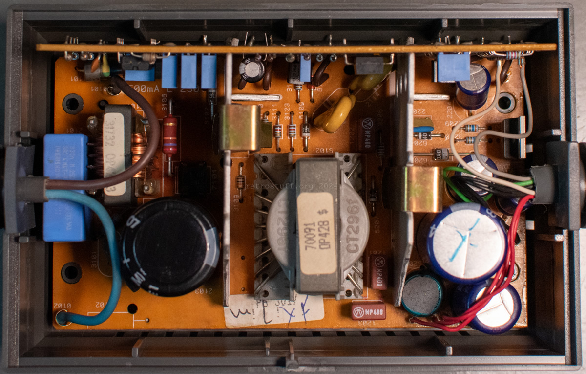
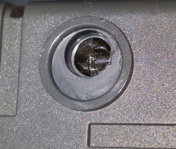
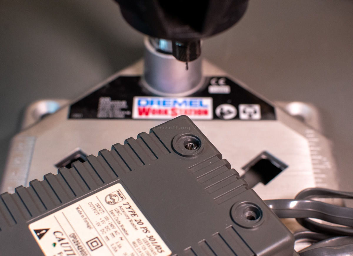
20PS301 (22ER9156)
External power supply unit for CDI 450 and 550, as well as all other top-loading CD-i players with Roboco mainboards. It is very similar to the PSU 20PS303, but has a few more components so that it can be controlled with the on/off switch in the CD-i player.
The PSU is connected to the CD-i player via an RJ45 (8P8C) plug.
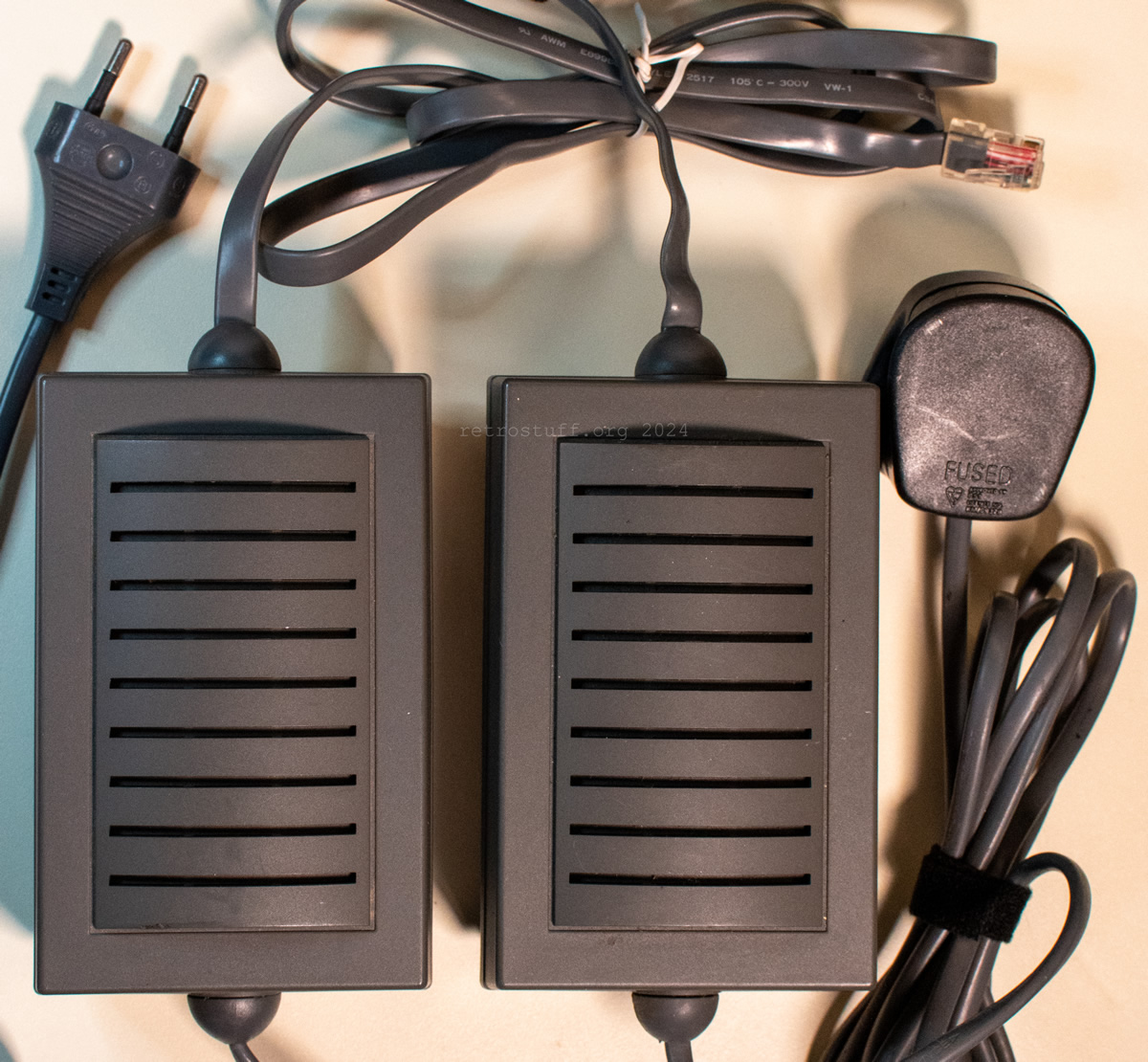
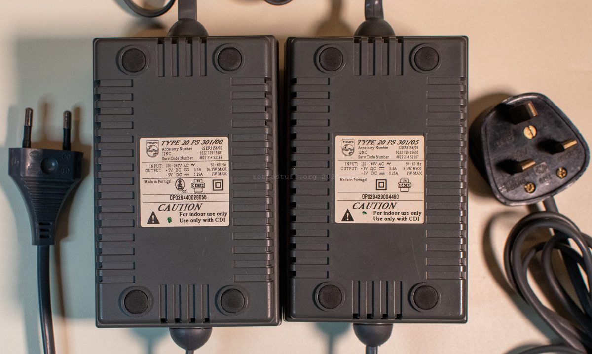
Known variants
- /00 (9022 729 15601, 4822 214 52166) – EU version with Europlug (Type C).
- /05 (9022 729 15605, 4822 214 52167) – UK version with BS 1363 plug (Type G).
- /11 (9022 729 15611, 4822 214 52168) – Japan version with polarised NEMA 1-15P plug (LT-301).
- /17 (4822 214 52169) – US version with polarised NEMA 1-15P plug. Neutral is connected to GND with resistor 3102 (10 MΩ “Use only in UL/CSA Version” according to the service manual).
Technical data
Service Manual: CDI 450/550 (/00/05/11/17)
Input: 110 – 240 V AC 50-60 Hz
Output: +5 V DC / 3,3 A / 16,5 W MAX, -5 V DC / 0,25 A / 2 W MAX
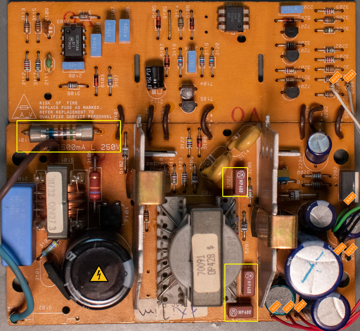
Fuses
- Main 1101 – T500mA L 250V glass fuse (5 x 20 mm)
- +5 V 1201 and 1203 – MP400 TE5 fuse
- -5 V 1202 – MP400 TE5 fuse
- (UK only: BS 1363 plug fuse “PMS 3A”)
Pinout
| PSU Pin | Signal | RJ45 Pin |
|---|---|---|
| 0202 red | +5 V | Pin 1 |
| 0201 white | sense / +5 V | Pin 2 |
| 0203 red | +5 V | Pin 3 |
| 0205 black | GND | Pin 4 |
| 0204 red | +5 V | Pin 5 |
| 0206 black | GND | Pin 6 |
| 0207 green | -5 V | Pin 7 |
| 0208 grey | ON/OFF | Pin 8 |
Disassembly, repair and alternatives
These power supply units are very robust and almost never need servicing. However, sometimes the tabs on the RJ45 plugs break off or the PSUs seemingly get lost on the second-hand market. This section will deal with these issues.
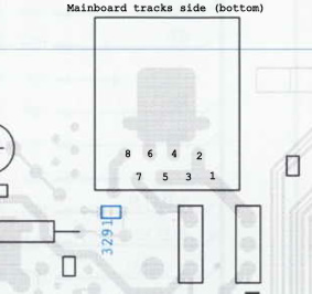
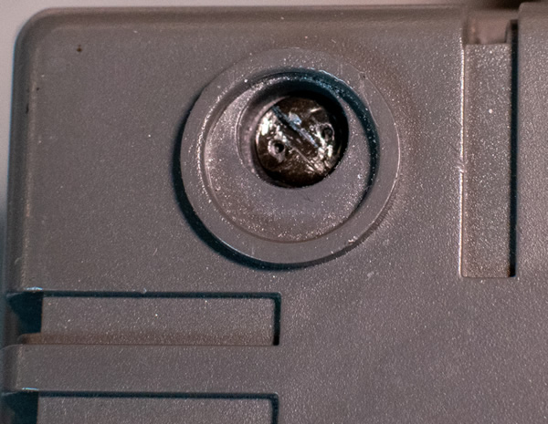
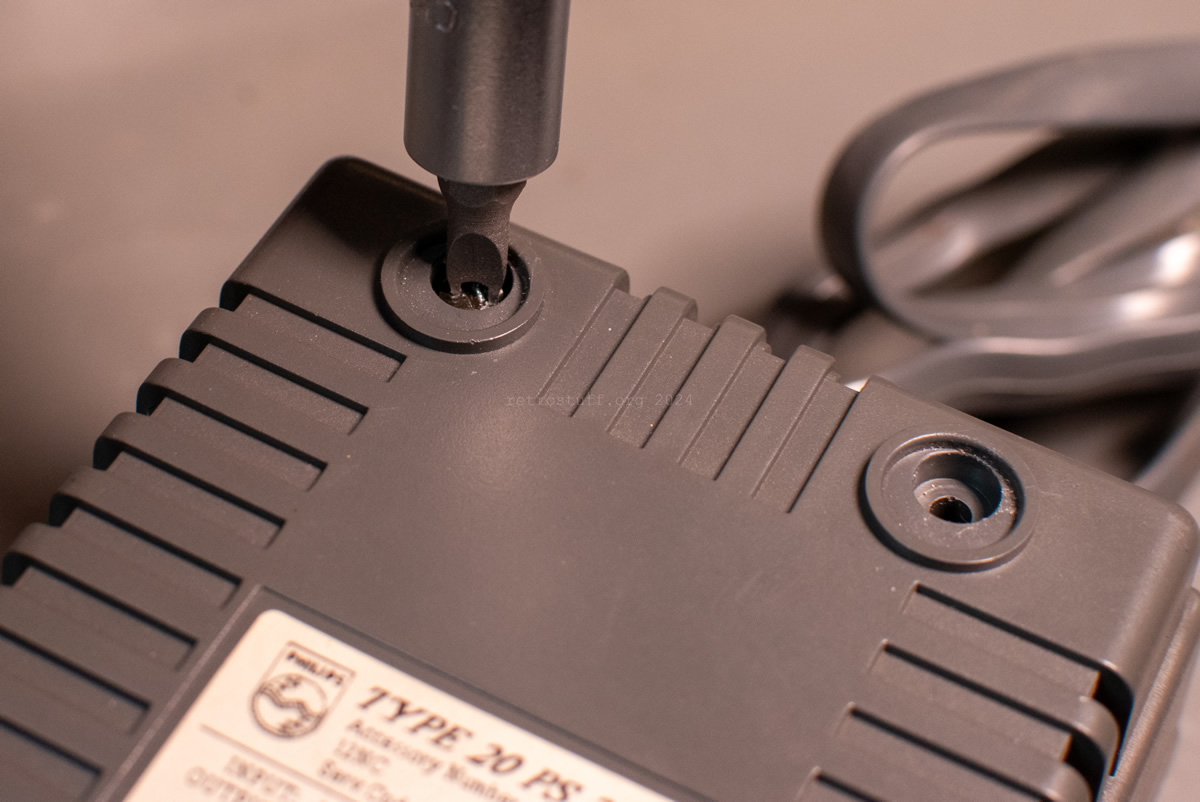
One-way screws
If you want to replace a blown fuse, you must first get inside. There are usually one-way screws under the rubber feet that are designed to prevent tampering (and in this case, maintenance). There are special tools and destructive methods to remove these types of screws. As these screws are recessed in the casing, there are not many options here. I decided to drill two small holes in the screws so that they can be unscrewed with a spanner screwdriver to finally get to the inside.
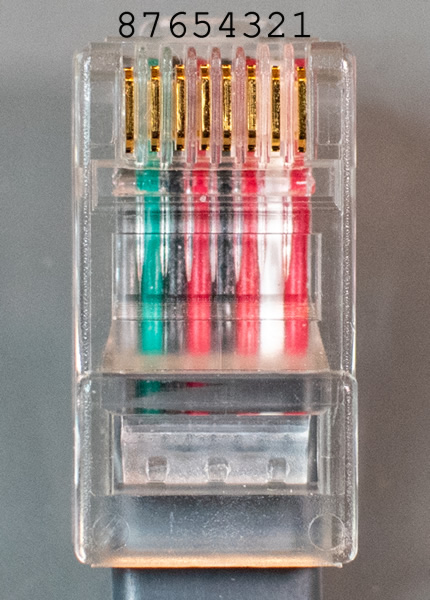
RJ45 tab
If the tab of the RJ45 connector breaks off, the power supply will still work properly and may not cause you any problems when playing CD-i. However, the connection is not very reliable and could be accidentally interrupted. There are two ways to re-establish a stable connectivity:
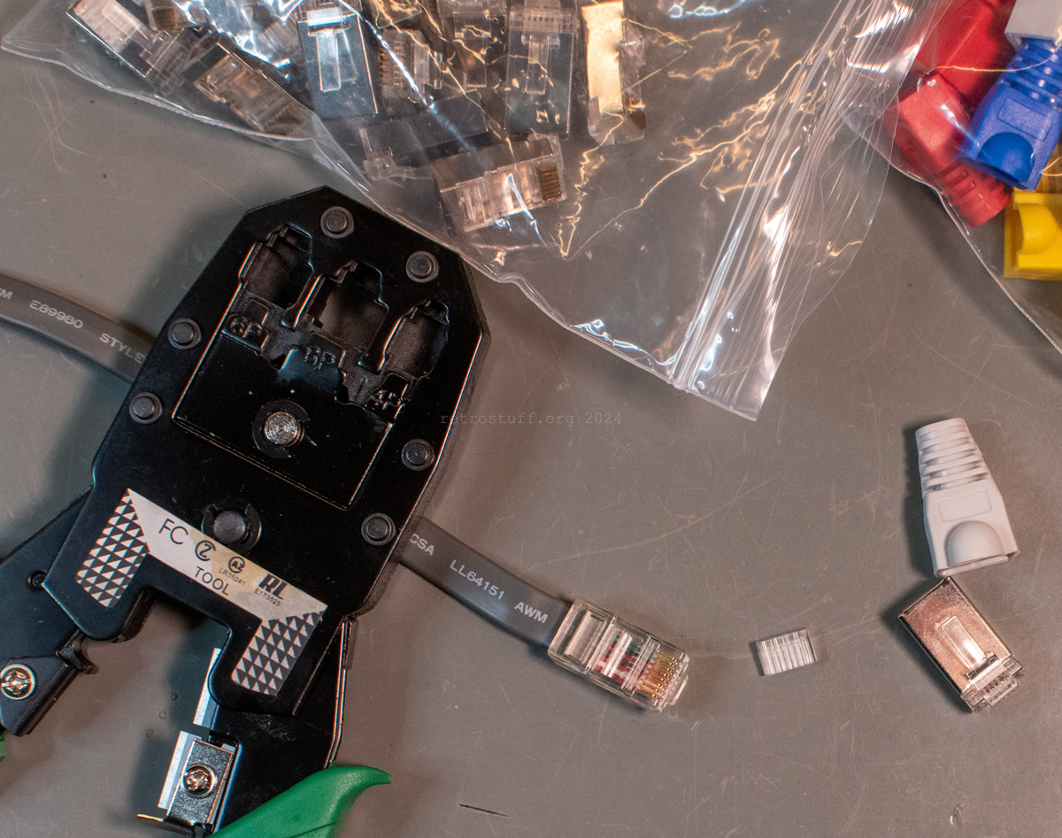
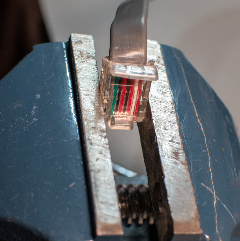
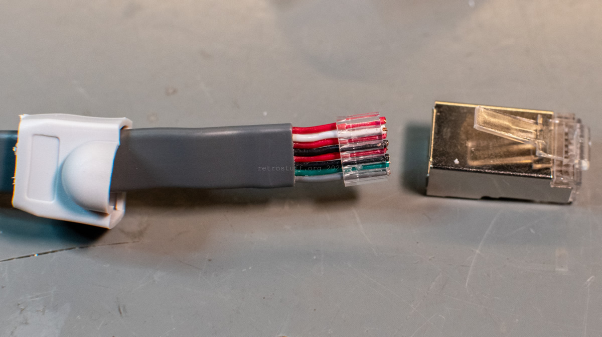
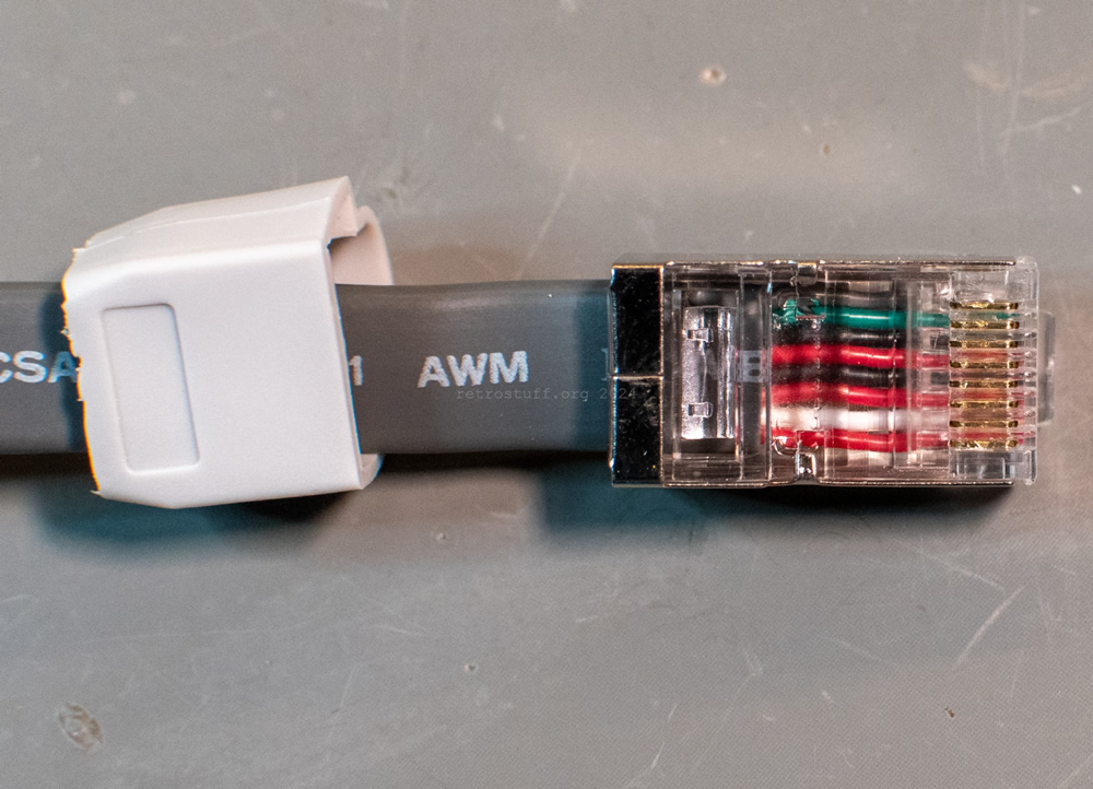
- Crimp a new plug
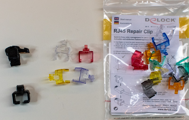
For this, the old plug must first be cracked, preferably without damaging the conductors. Then simply follow the instructions for your crimping set (the picture shows a very cheap set – totally sufficient). It is up to you whether you also attach the boot, as its actual function (strain relief) does not work here due to the shape of the power cable – the boot must be cut open so that it fits.
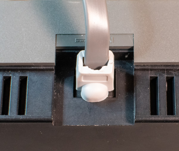
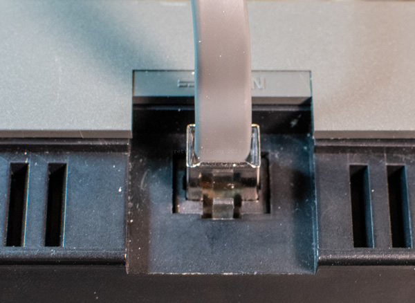
- Repair the tab
Here are two examples of the many clips you can either print yourself or buy: Ethernet | RJ45 clip to secure/repair/fix broken tab by guss67 and Delock RJ45 Secure Clip Starter Set 20 pieces.
Replacement power supplies
Finding a replacement PSU is not as straightforward because, apart from the plug, these CD-i players have very specific needs:
two voltages (+5 V / 3,3 A and -5 V / 0,25 A) and that it can be switched remotely by connecting pin 8 to GND. A very common substitute is an arcade power supply that provides both voltages but renders the built-in power switch useless. A breakthrough was made in 2022 by Jeff Chen, who first used an old ATX power supply and then developed a foolproof adapter for two regular +5 V power supplies.
Whichever solution you choose, make sure that you adhere strictly to the pin numbering and use separate conductors for all +5 V and GND lines – otherwise your equipment will be damaged.
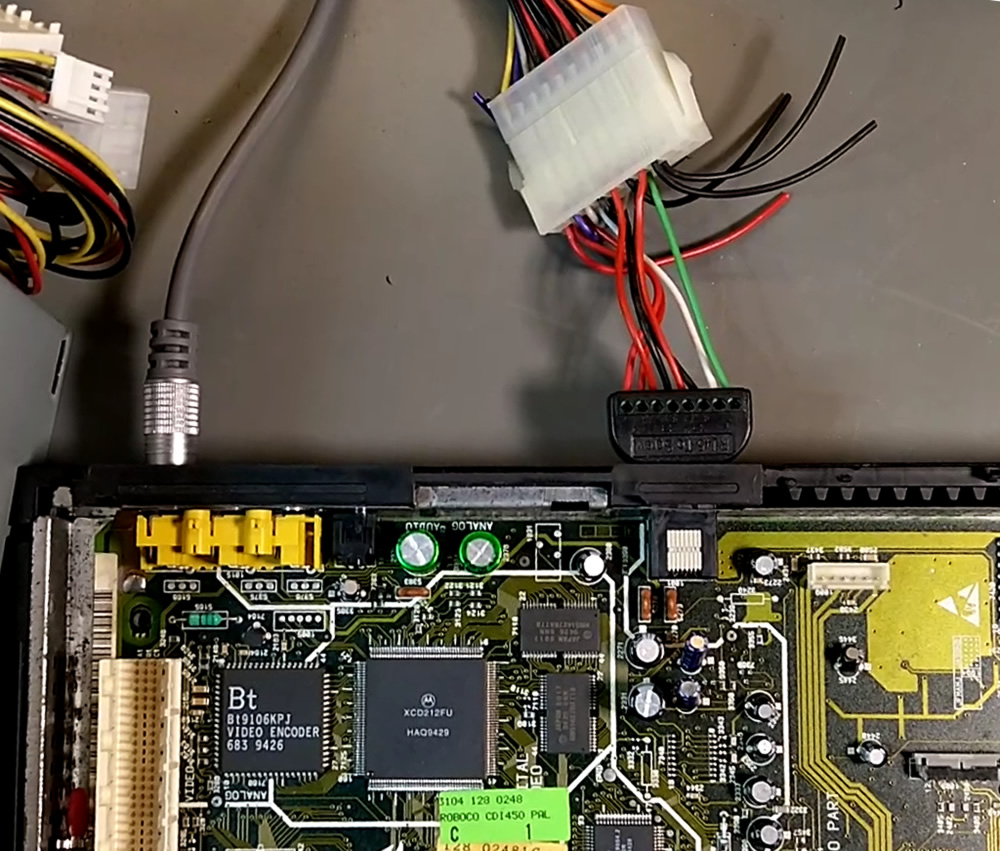
- Arcade power supply to RJ45
1 – +5 V (3,3 A)
2 – (+5 V optional)
3 – +5 V
4 – GND
5 – +5 V
6 – GND
7 – -5 V (0,25 A)
8 – n. c.
- ATX-1.x power supply to RJ45
Warning: There are several standard and non-standard wirings. Double-check the +5 V, -5 V, GND and PS_ON lines before plugging it into a CD-i player!
1 – +5 V (3,3 A)
2 – (+5 V optional)
3 – +5 V
4 – GND
5 – +5 V
6 – GND
7 – -5 V (pin 18)
8 – PS_ON (pin 14)
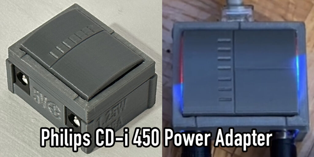
- Philips CD-i 450/550 Power Adapter
Jeff Chen’s GitHub repository with instructions, PCB design and STL files.
- G2 PSU for Philips CDi 450/550
This replacement PSU requires only one DC power supply and can be bought in zaxour’s Ko-fi Shop.
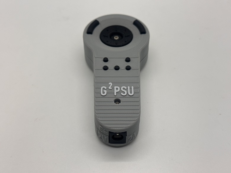
(The last two pictures are courtesy of Jeff Chen and Zaxour.)
20PS302
Power supply unit for Mono III CD-i players, e.g., CDI 210/40, 210/57 and 220/60, 220/77.
It is identical to the Mono IV PSU 20PS306, but has different fuse types on the power rails.
Known variants
- /00 (3122 137 21642) – EU version with C8 inlet.
- /17 – US version with polarised C8P inlet. Neutral (squared side) is connected to GND with resistor 3102 (10 MΩ “Use only in UL/CSA Version” according to the service manual).
Technical data
Service Manual: CDI 210 (/40/41/45) and CDI 220 (/60/62/65/77)
Input: 110 – 240 V AC
Output: +5 V, -5 V, +24 V
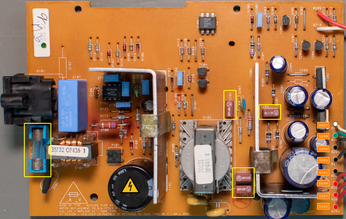
Fuses
- Main 1101 – T1.0A L 250V glass fuse (5 x 20 mm)
- +5 V 1201 and 1203 – MP400 TE5 fuse
- -5 V 1202 – MP400 TE5 fuse
- +24 V 1204 – MP400 TE5 fuse
Pinout
| PSU Pin | Signal | MB Pin |
|---|---|---|
| 0202 red | +5 V | 1001 Pin 1 |
| 0203 red | +5 V | 1001 Pin 2 |
| 0204 red | +5 V | 1001 Pin 3 |
| 0201 black | GND | 1001 Pin 4 |
| 0205 black | GND | 1001 Pin 5 |
| 0206 black | GND | 1001 Pin 6 |
| 0208 green | +24 V | 1001 Pin 7 |
| 0207 white | -5 V | 1001 Pin 8 |
20PS303
This is one of the two power supply units in the FW308i Mini System and only powers the CD-i part. It is very similar to the PSU 20PS301 (22ER9156), but has fewer components as it is controlled via the switch board.
Even though it is a multi-voltage PSU, this does not mean that the FW308i can be operated with other voltages without further ado. The second power supply (transformer for FW Part) is configured with wire jumpers for 220 – 230 V. However, according to the service manual, there is an unpopulated switch 1281 for switching between 120 V and 230 V.
For the time being, I will only provide information about the PSU for the CD-i part in this article. Further information on the other components can be found in the FW380i repair article.
Known variants
- (3122 137 21751) – EU version.
Technical data
Service Manual: FW380i (/00/00S/05)
Input: 100 – 240 V AC / 50/60 Hz
Output: +5 V, -5 V
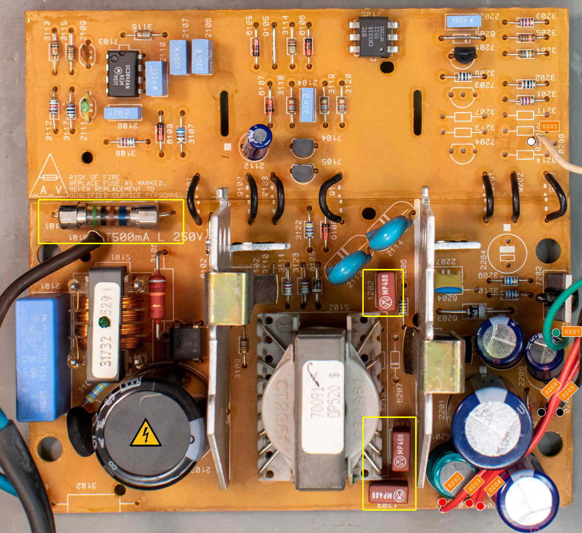
Fuses
- Main 1101 – T500mA L 250V glass fuse (5 x 20 mm)
- +5 V 1201 and 1203 – MP400 TE5 fuse
- -5 V 1202 – MP400 TE5 fuse
Pinout
| PSU Pin | Signal | MB Pin |
|---|---|---|
| 0201 white | sense / +5 V | 1013 Pin 1 |
| 0202 red | +5 V | 1013 Pin 2 |
| 0203 red | +5 V | 1013 Pin 3 |
| 0204 red | +5 V | 1013 Pin 4 |
| 0205 black | GND | 1013 Pin 5 |
| 0206 black | GND | 1013 Pin 6 |
| 0207 green | -5 V | 1013 Pin 7 |
| ./. | GND | 1013 Pin 8 |
Mono IV
There are many different power supply units for the Mono IV generation. These are also multi-voltage switched-mode PSUs and can be used in other regions of the world without step-up or step-down converters. Again, CD-i players built into TVs are an exception.
20PS304
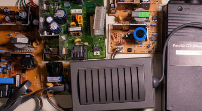
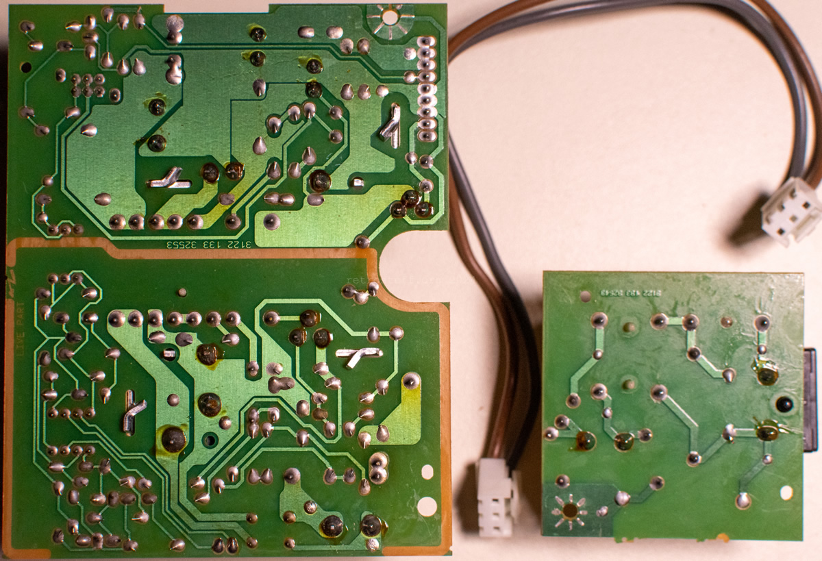
The power supply units for the small Mono IV CD-i players CDI 470 and 490 are divided into two parts. The small part with the power inlet is located at the rear of the player, the large part with the power switch at the front.
Known variants
- /00 (3122 137 21812) – EU version with C8 inlet.
- /17 – US version with polarised C8P inlet. Neutral (squared side) is connected to GND with resistor 3102 (10 MΩ “Use only in UL/CSA Version” according to the service manual).
Technical data
Service Manual: CDI 470 (/00/05/06)
Input: 100 – 240 V AC 50-60 Hz
Output: +5 V, -5 V
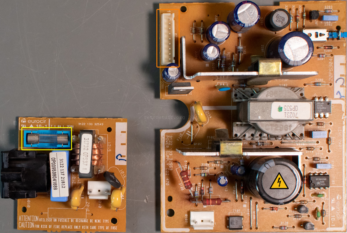
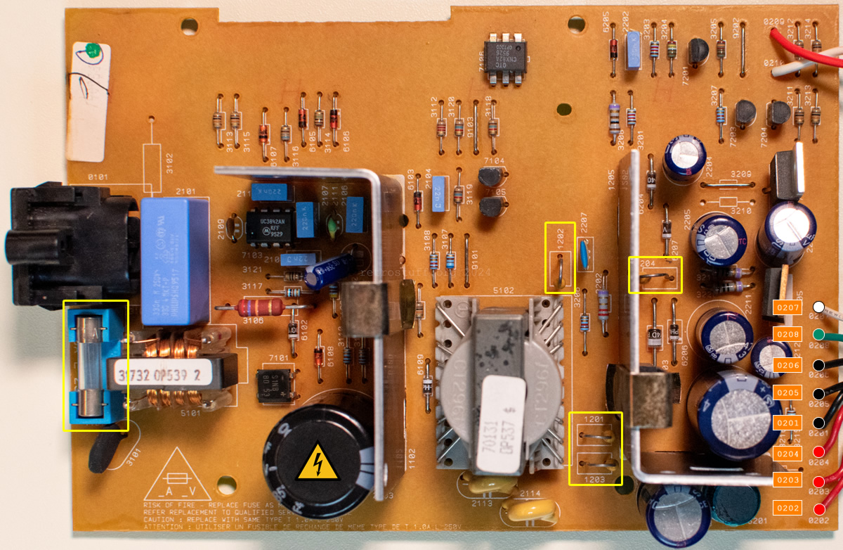
Fuses
- Main 1101 – T1.0A L 250V glass fuse (5 x 20 mm)
There are no additional fuses on the power supply PCBs. See this article about fuses on the mainboard.
Pinout
| PSU Pin | Signal | MB Pin |
|---|---|---|
| 0201 Pin 1 | +5 V | 1001 Pin 1 |
| 0201 Pin 2 | +5 V | 1001 Pin 2 |
| 0201 Pin 3 | +5V | 1001 Pin 3 |
| 0201 Pin 4 | sense / +5 V | 1001 Pin 4 |
| 0201 Pin 5 | GND | 1001 Pin 5 |
| 0201 Pin 6 | GND | 1001 Pin 6 |
| 0201 Pin 7 | GND | 1001 Pin 7 |
| 0201 Pin 8 | -5 V | 1001 Pin 8 |
| 0201 Pin 9 | n.c. | 1001 Pin 9 |
20PS305
Not yet discovered.
20PS306
Internal power supply unit for large Mono IV consumer players, such as CDI 220/80 and 220/97C.
It is identical to the Mono III PSU 20PS302, but has different fuse types on the power rails.
Known variants
- /00 (3122 427 20051) – EU version with C8 inlet.
- /17 – US version with polarised C8P inlet. Neutral (squared side) is connected to GND with resistor 3102 (10 MΩ “Use only in UL/CSA Version” according to the service manual).
Technical data
Service Manual: CDI 220 (/80/85/97)
Input: 100 – 240 V AC 50-60 Hz
Output: +5 V, -5 V, +24 V
Fuses
- Main 1101 – T1.0A L 250V glass fuse (5 x 20 mm)
- +5 V 1201 and 1203 – axial pico fuse 4000
- -5 V 1202 – axial pico fuse 4000
- +24 V 1204 – axial pico fuse 4000
Compared to 20PS302, this PSU does not have Littelfuse MP400 TE5 fuses, but axial pico fuses labelled “4000” on the power rails (thanks to Stovent for checking this first). However, the details in the parts lists in the service manuals are identical, “4822 252 51179 PROT DEV 65V 4A” for both fuse types.
Pinout
| PSU Pin | Signal | MB Pin |
|---|---|---|
| 0202 red | +5 V | 1001 Pin 1 |
| 0203 red | +5 V | 1001 Pin 2 |
| 0204 red | +5 V | 1001 Pin 3 |
| 0201 black | GND | 1001 Pin 4 |
| 0205 black | GND | 1001 Pin 5 |
| 0206 black | GND | 1001 Pin 6 |
| 0208 green | +24 V | 1001 Pin 7 |
| 0207 white | -5 V | 1001 Pin 8 |
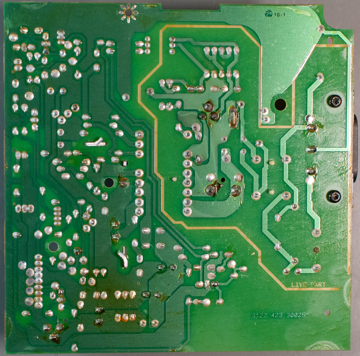
20PS307
Internal Class 1 power supply unit for all Mono IV professional players (CDI 615, 660 and 670).
Known variants
- /00 (3122 427 20082) – EU version with C14 inlet.
The 10 MΩ resistor 3102, which is only present in PSUs for North America, is also fitted here. Although most EU mains plugs are not polarised, there is no detrimental effect if earth is connected to live instead of neutral via the resistor.
Technical data
Service Manual: n/a
Input: 100-240 V AC 50-60 Hz
Output: +5 V, -5 V, +12 V
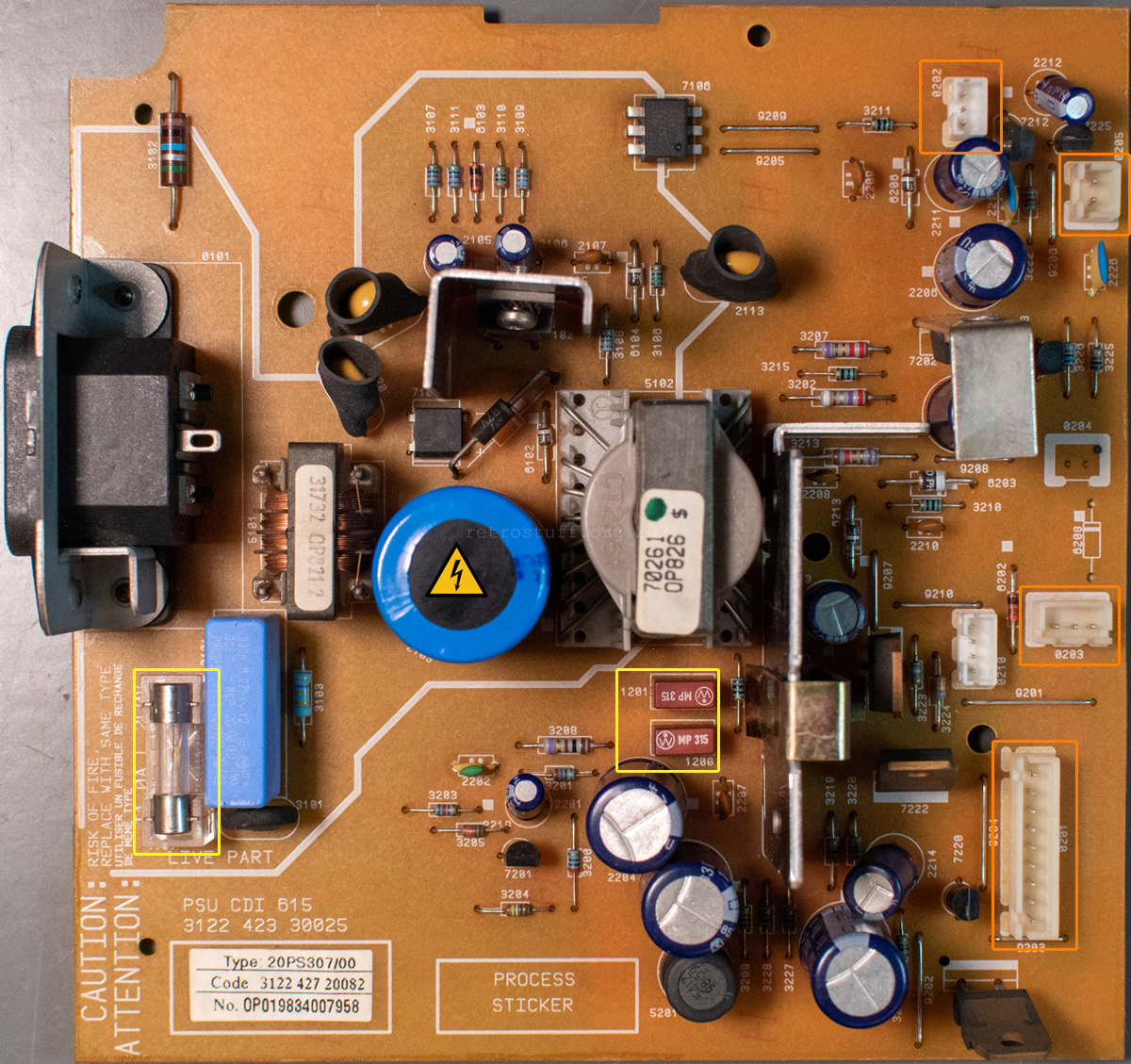
Fuses
- Main 1101 – T1.0A L 250V glass fuse (5 x 20 mm)
- +5 V 1200 and 1201 – MP315 TE5 fuse
Pinout
| PSU Connector/Pin | Signal | Destination |
|---|---|---|
| 0201 Pin 1 | +5 V | MB 1001 Pin 1 |
| 0201 Pin 2 | +5 V | MB 1001 Pin 2 |
| 0201 Pin 3 | +5VSTB | MB 1001 Pin 3 |
| 0201 Pin 4 | +5 V | MB 1001 Pin 4 |
| 0201 Pin 5 | GND | MB 1001 Pin 5 |
| 0201 Pin 6 | GND | MB 1001 Pin 6 |
| 0201 Pin 7 | GND | MB 1001 Pin 7 |
| 0201 Pin 8 | -5 V | MB 1001 Pin 8 |
| 0201 Pin 9 | STBV | MB 1001 Pin 9 |
| 0202 Pin1 | +12 V | Combi 1001 Pin 1 (goes to MB 1021 Pin 9) |
| 0202 Pin2 | GND | Combi 1000 Pin 2 |
| 0202 Pin3 | GND | Combi 1000 Pin 3 |
| 0203 Pin 1 | +5 V | (to be confirmed) |
| 0203 Pin 2 | GND | (to be confirmed) |
| 0203 Pin 3 | GND | (to be confirmed) |
| 0205 Pin 1 | +12 V | (to be confirmed) |
| 0205 Pin 2 | GND | (to be confirmed) |
20PS308
Internal power supply unit for the last Mono IV consumer player CDI 740. There is no service manual and not much is known about it. Fortunately, Jorne / MrMii6 was able to obtain one of these rare devices and took a lot of photos.
Known variants
- /00 (3122 427 20283) – EU version with C8 inlet.
Technical data
Service Manual: n/a
Input: 100-240 V AC 50-60 Hz
Output: +5 V, -5 V, +12 V (to be confirmed)
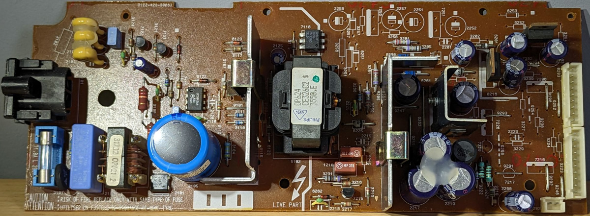
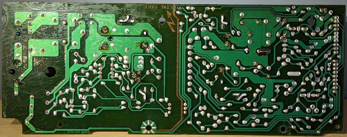
(Photos courtesy of Jorne / MrMii6.)
Fuses
- Main 1101 – T1.0A L 250V glass fuse (5 x 20 mm)
- +5 V 1215 and 1216 – MP315 TE5 fuse
Pinout
(to be confirmed)
GoldStar / LG
[Further details will follow.]
Kyocera
[Further details will follow.]
Sony
[Further details will follow.]
Changelog
2024-09-29: Initial version published.
2026-03-22: Added Mono I/II PSU section. Added zaxour’s G2 PSU. Added further information on fuses. Minor corrections and cleanup.
2 thoughts on “Philips CD-i Power Supply Units”