
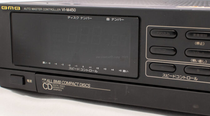
Master controller for Nikkodo / BMB CD karaoke systems. Like the BMB CDI-M1500 master controllers, it is similar to the Philips CDI 181 MultiMedia Controller (JNMS). The mainboards of these units were made by Kyocera. They all lack optical disc drives and require additional units (e.g. CDI 180 for JNMS and CDI-A1500 for BMB).
So far, four different hardware generations have been found, and there may be more. The hardware has evolved from being very similar to JNMS to something that hasn’t been seen in other CD-i players. This fourth generation moves away from Philips/Kyocera mainboards even more: Some components of the analogue video section have been moved to a separate PCB, and a Gate Array DVC (GMPEG) chipset has been added to the mainboard.
I use the first character of the CDI-M1500 serial numbers to identify different mainboards/generations. For the VI-M450, only one generation is currently known.
- CDI-M1500 A unit – mainboard PDCDG4001D
- CDI-M1500 L unit – mainboard PDCDG4002B
- CDI-M1500 V unit – mainboard PDCDG4003B
- VI-M450 unit – mainboard PDCDG4004A (this WIP Page)
Resources
- Service manual: N/A
- Previous listings with more hardware
- BMB company history
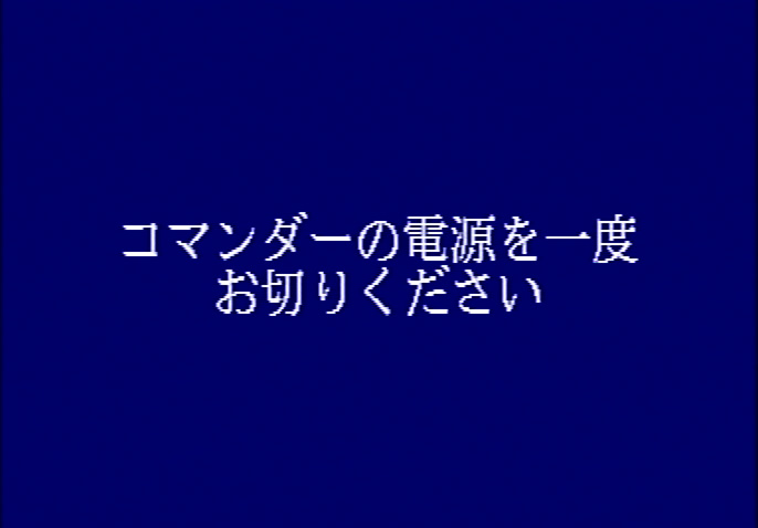
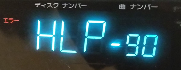
Player shell
I haven’t been able to convince this unit to display a shell like the CDI-M1500 units have so far. Instead, error messages are displayed 55 seconds after powering on:
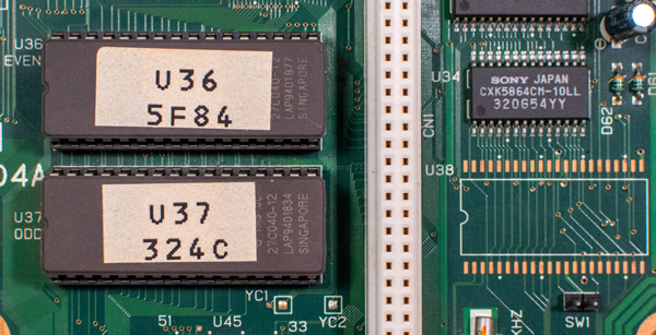
System ROM
The system ROM of the VI-M450 is 1 MB in size, which is twice the capacity of a CDI-M1500 system ROM. As with the V unit, this mainboard is also compatible with two types of system ROMs. In this instance, two TI TMS27C040-12 524288 by 8-bit EPROMs are populated (U36, EVEN and U37, ODD). There is an unpopulated space designated for a mask ROM (U38) with a jumper for CE (SW1).
Modules and checksums:
Addr Size Owner Perm Type Revs Ed # Crc Module name
-------- -------- ----------- ---- ---- ---- ----- ------ ------------
000010b2 26650 0.0 0555 Sys a000 83 090798 kernel
000078cc 364 0.0 0555 Sys 8002 22 2bc19a init
00007a38 1106 0.0 0555 Sys a013 19 df7e12 rp5c15
00007e8a 176 0.0 0777 5 8001 1 9e13b1 csd
00007f3a 4810 0.0 0555 Sys a000 30 fddadc csdinit
00009204 12328 0.0 0555 Sys a000 9 55d2a2 fpu
0000c22c 13236 0.0 0555 Prog e001 2 262444 p2init
0000f5e0 47098 1.0 0555 Trap c005 15 5dd885 csl
0001adda 18082 10.48 0555 Trap c00a 6 5f673d cio
0001f47c 7798 1.0 0555 Trap c001 13 46c5dc math
000212f2 2270 0.0 0555 Fman a000 35 d6a976 pipeman
00021bd0 5592 0.0 0555 Fman a000 17 63023d nrf
000231a8 4510 0.0 0555 Fman a003 96 a4d145 cdfm
00024346 2852 0.0 0555 Fman a010 36 f247db ucm
00024e6a 13594 0.225 0555 Fman a001 34 338178 mpfm
00028384 172 0.0 0555 Driv a000 1 407f81 null
00028430 774 0.0 0555 Driv a001 6 81a3e9 nvdrv
00028736 12300 0.0 0555 Driv a002 89 76bda8 cddrvm
0002b742 66622 0.0 0555 Driv a011 51 1fa0aa video
0003bb80 2674 0.0 0555 Driv a00c 12 ca4792 ptrdrv
0003c5f2 2012 0.0 0555 Driv a01c 28 9269a1 env68681
0003cdce 1724 0.0 0555 Driv a014 20 795eb1 tc68681
0003d48a 2948 0.0 0555 Driv a00a 10 ed1af5 comdrv
0003e00e 218 0.0 0555 Driv a000 1 5aa9f3 nill
0003e0e8 30310 0.0 0555 Driv a000 2 dd2fcc mpmoto
0004574e 102 0.0 0555 Desc 8000 2 cf450e pipe
000457b4 94 0.0 0555 Desc 8000 1 1ba307 nvr
00045812 130 0.0 0555 Desc 8000 1 e8a6c5 cd
00045894 130 0.0 0555 Desc 8000 1 96701a ap
00045916 130 0.0 0555 Desc 8000 1 876608 vid
00045998 128 0.0 0555 Desc 8000 1 66818a ptr
00045a18 132 0.0 0555 Desc 8000 1 652843 env
00045a9c 130 0.0 0555 Desc 8000 1 8e897c tc
00045b1e 128 0.0 0555 Desc 8000 1 f81b48 cmd
00045b9e 118 0.0 0555 Desc 8020 2 be7d14 nil
00045c14 798 0.0 0555 Desc 8000 1 c02224 mv
00045d24 526 0.0 0555 Prog a000 1 c02224 mv.9k
00045f32 804 0.0 0555 Desc 8000 1 3a9faa ma
00046042 532 0.0 0555 Prog a000 1 3a9faa ma.9k
00046256 16512 0.0 0333 Data 8002 1 83b435 dspcode
0004a2d6 2992 0.0 0555 Data 8020 1 191a59 FONT8X8
0004ae86 3424 0.0 0555 Data 8001 1 7941a6 stop.cl7
0004bbe6 19680 0.0 0033 Data 8000 1 64444d jidai.grlib.rl7
000508c6 20512 0.0 0033 Data 8000 1 79ff05 jikyoku.grlib.rl7
000558e6 18688 0.0 0033 Data 8000 1 c3d1fb request1.grlib.rl7
0005a1e6 18960 0.0 0033 Data 8000 1 1d9758 request2.grlib.rl7
0005ebf6 18720 0.0 0033 Data 8000 1 33b526 request3.grlib.rl7
00063516 15680 0.0 0033 Data 8000 1 81fa6f shinpu.grlib.rl7
00067256 17232 0.0 0033 Data 8000 1 f01906 yoyaku.grlib.rl7
0006b5a6 135904 0.0 0033 Data 8003 1 a84a27 BMB_IDX
0008c886 18992 0.128 0033 Data 8000 1 0e954d BMB_JID
000912b6 48418 300.302 0555 Prog 8006 22 13bb00 KARAOKE$.NK1
0009cfd8 133788 0.128 0555 Prog 8001 114 42b699 KYOCERA_CORP_CI16_h
000bda74 4820 0.128 0555 Prog c009 104 a4c1c8 seldisc
000bed48 24404 0.0 0555 Prog c001 10 59be48 cdg_aplk
000c4c9c 34668 0.0 0555 Prog c001 9 f0b9e1 kcmp
000cd408 33758 0.0 0555 Prog 8001 6 4bfd33 ps_aging
000d57e6 92276 0.0 0555 Data 8001 1 faeb0a stx.dyuv
File Addr Size Type Description
------------------ -------- ------ ------------------ ------------
vim450a00.rom 00000000 1024K vim450a.rom BMB VI-M450 system ROM
vim450a00.rom 00000000 1024K vim450a.mdl BMB VI-M450 Auto Master Controller
vim450a00.rom 00000000 1024K vim450.brd BMB VI-M450 board
vim450a00.rom 00000000 1024K vim450a.sum Sum: 5F84:324C
vim450a00.rom 00000000 1024K vim450a.crc CRC: 0F0BCEB2
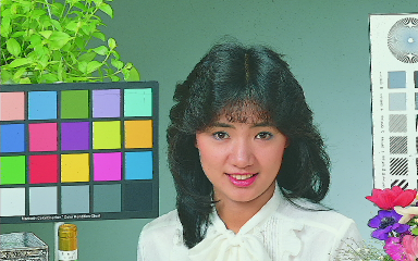
vim450a00.rom 00000000 1024K vim450a.md5 MD5: D4105F1021E6CCDA2555CE2116D90AADAn image (stx.dyuv) found in the system ROM, possibly for calibration purposes.
PCBs and markings
Photo after opening the unit for the first time (and removing the two metal supports). There is some dirt and a few insect parts.

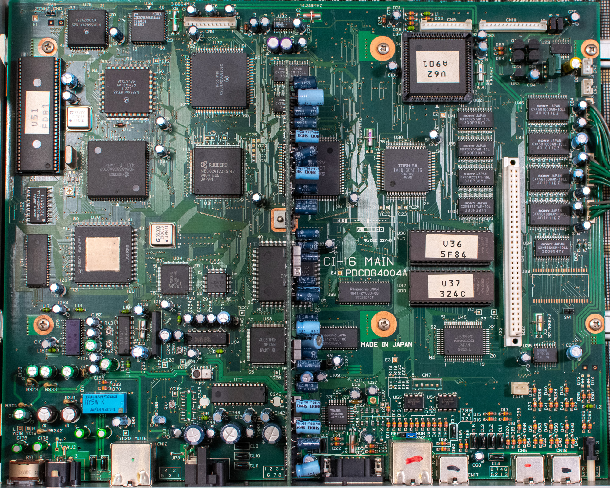
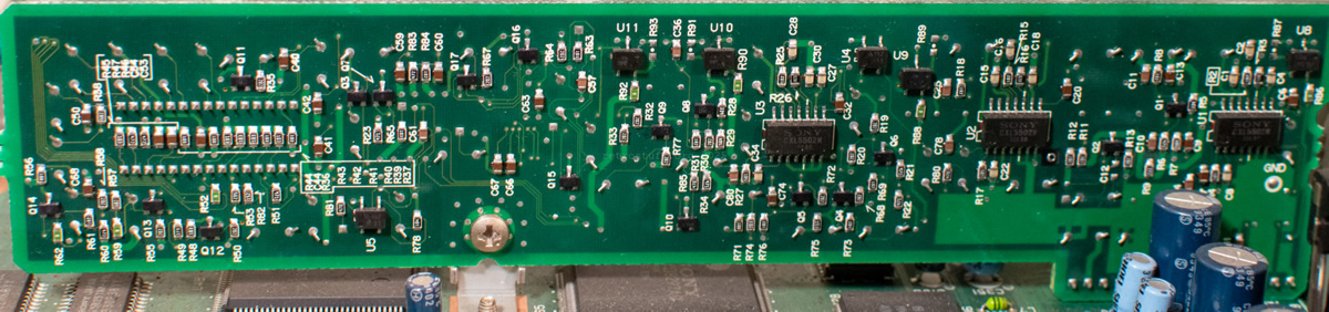
PDCDG4004A CI-16 MAIN (mainboard, front)
A better view of the mainboard after the initial cleaning. The video board in the center is soldered to the mainboard. Note the GMPEG DVC chipset on the left side (and compare it to the DVC found in this article).
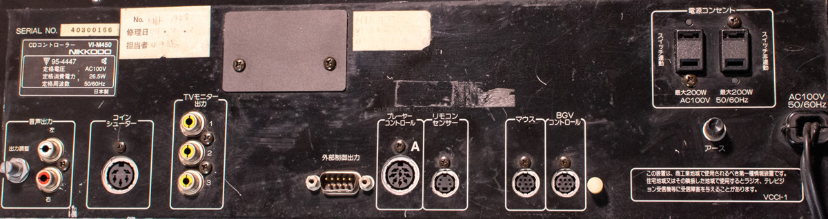
Back connectors
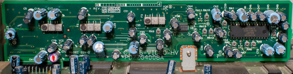
PDZZG4008A CI-16-VIDEO-HV (video board)
PSU Nichicon CI-1PS
The power supply is still working, but given the smell it emits, I suspect that it is in the same poor condition as the other units’ PSUs.
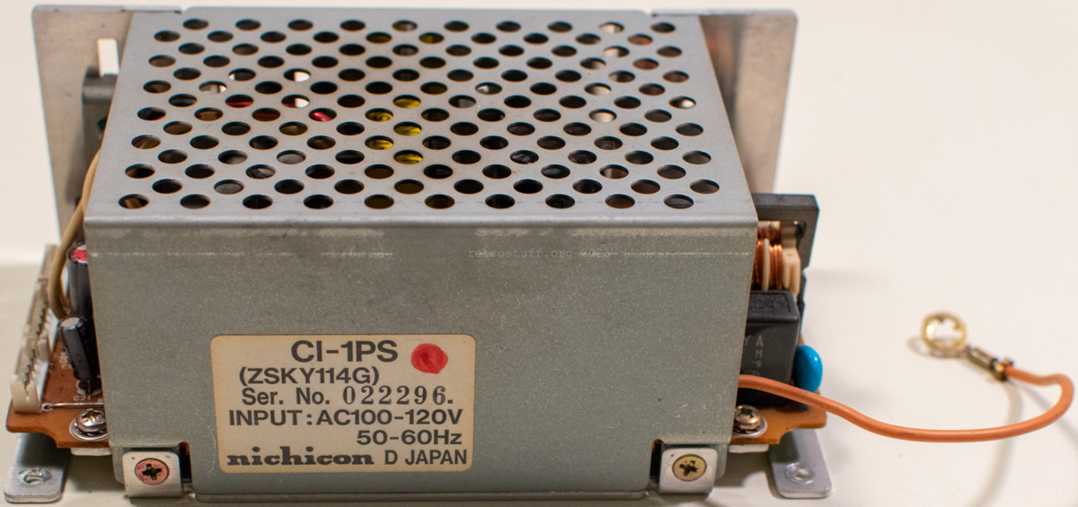
CI-1PS
(ZSKY114G)
Ser. No. 022296.
INPUT:AC100-120V
50-60Hz
nichicon D JAPAN
To-do
- Figure out how to boot the unit without it displaying error messages.
- Complete inspection of all PCBs and creation of chip marking lists.
- Inspection of the power supply unit and identification of all components.
- Replacement of all electrolytic capacitors in the PSU.
Credits
Many thanks to
– Zero for finding this unit
– CD-i Fan for pointing out the GMPEG chipset and doing ROM analysis
– ogarvey for converting stx.dyuv
History
2025-06-13: Initial WIP Page published
2025-06-14: Updated System ROM information