
When I finally fixed my consolized MV1FZS last month and was able to play some games again, I noticed that it outputs mono sound only. It is now time to make some additional modifications to it.
5V Mod
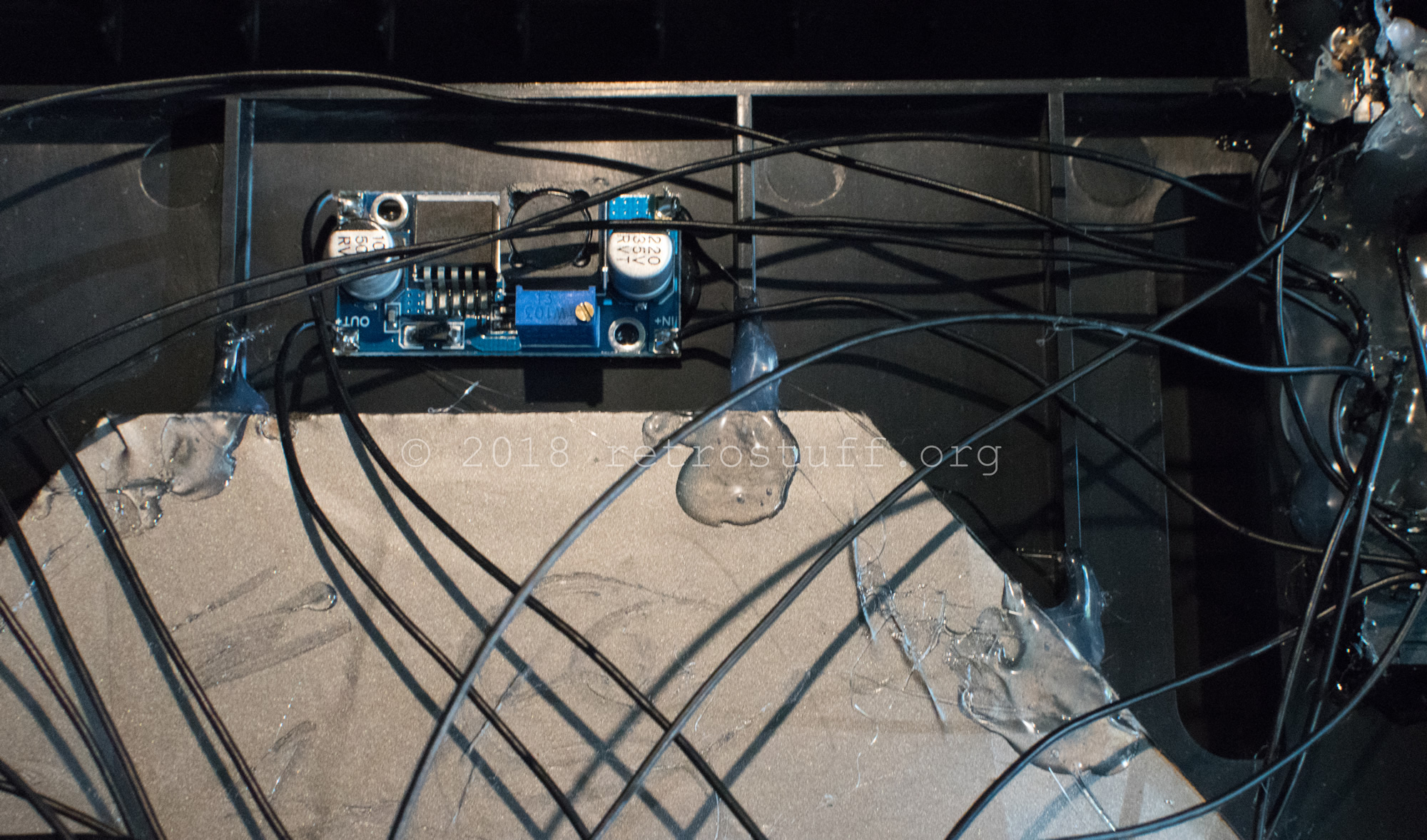
MVS boards need both 5V and 12V voltages, and 12V is used for the audio amp only. As I’m going to add a new stereo audio circuit, there is no need for the 12V feed anymore. This consolized MVS draws the 12V from the now obsolete XL6009E1 DC-DC converter:
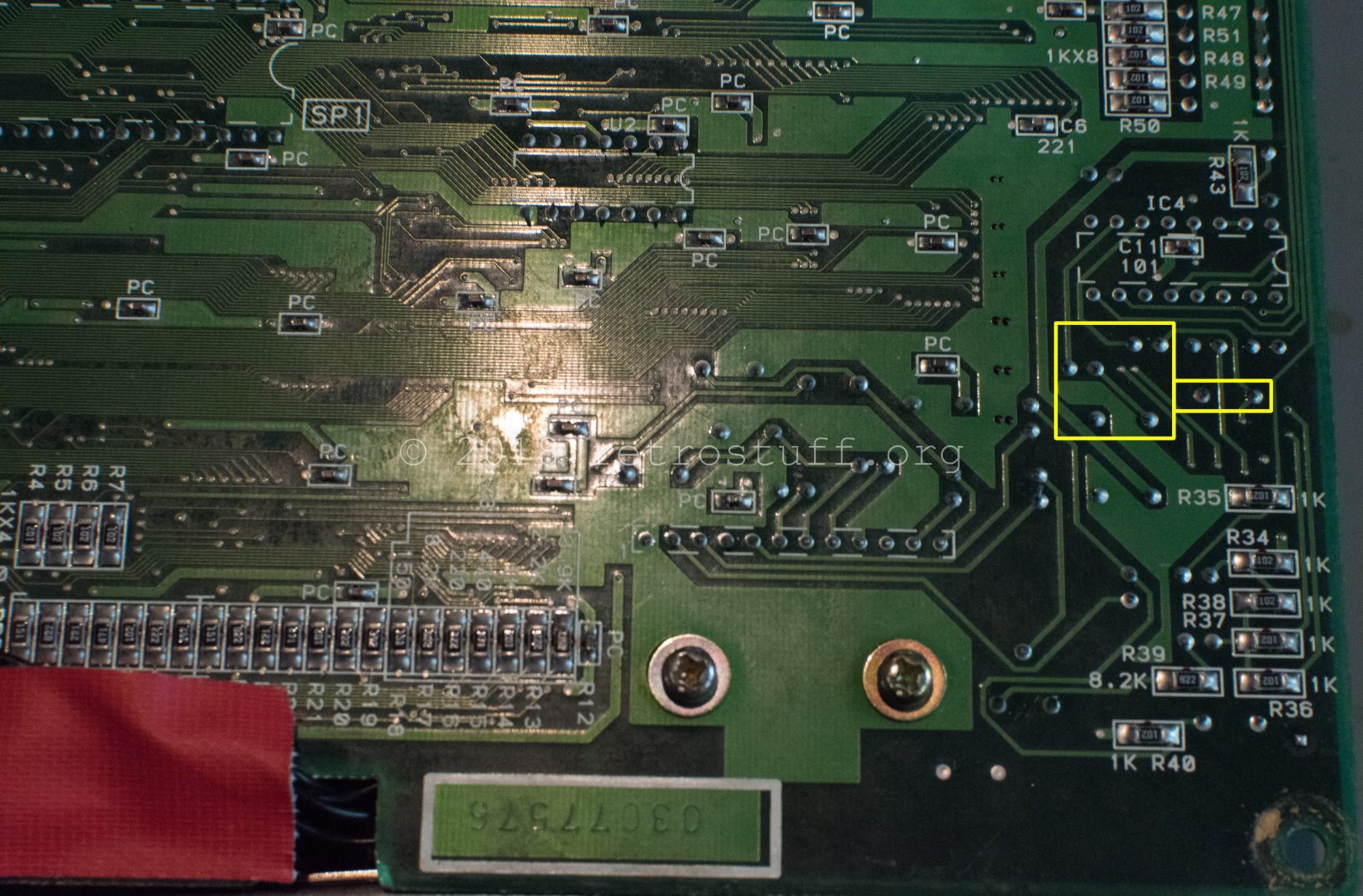
Once again, mmmonkey provides a good resource for the modification tutorials. I need to remove 4 components and change some traces. For full details, please read the tutorial ‘MV-1FZ 5V Only Mod’.
Stereo Mod
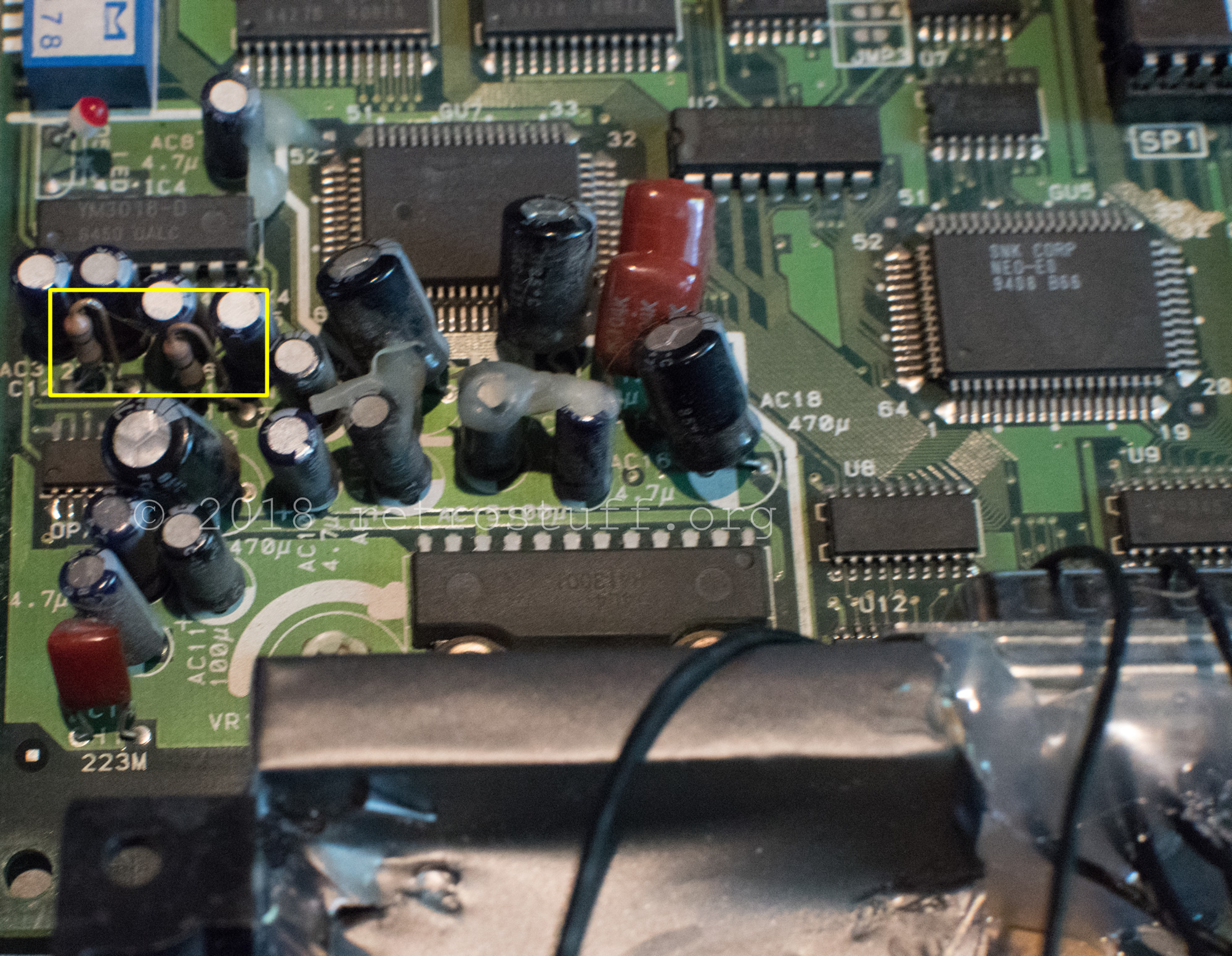
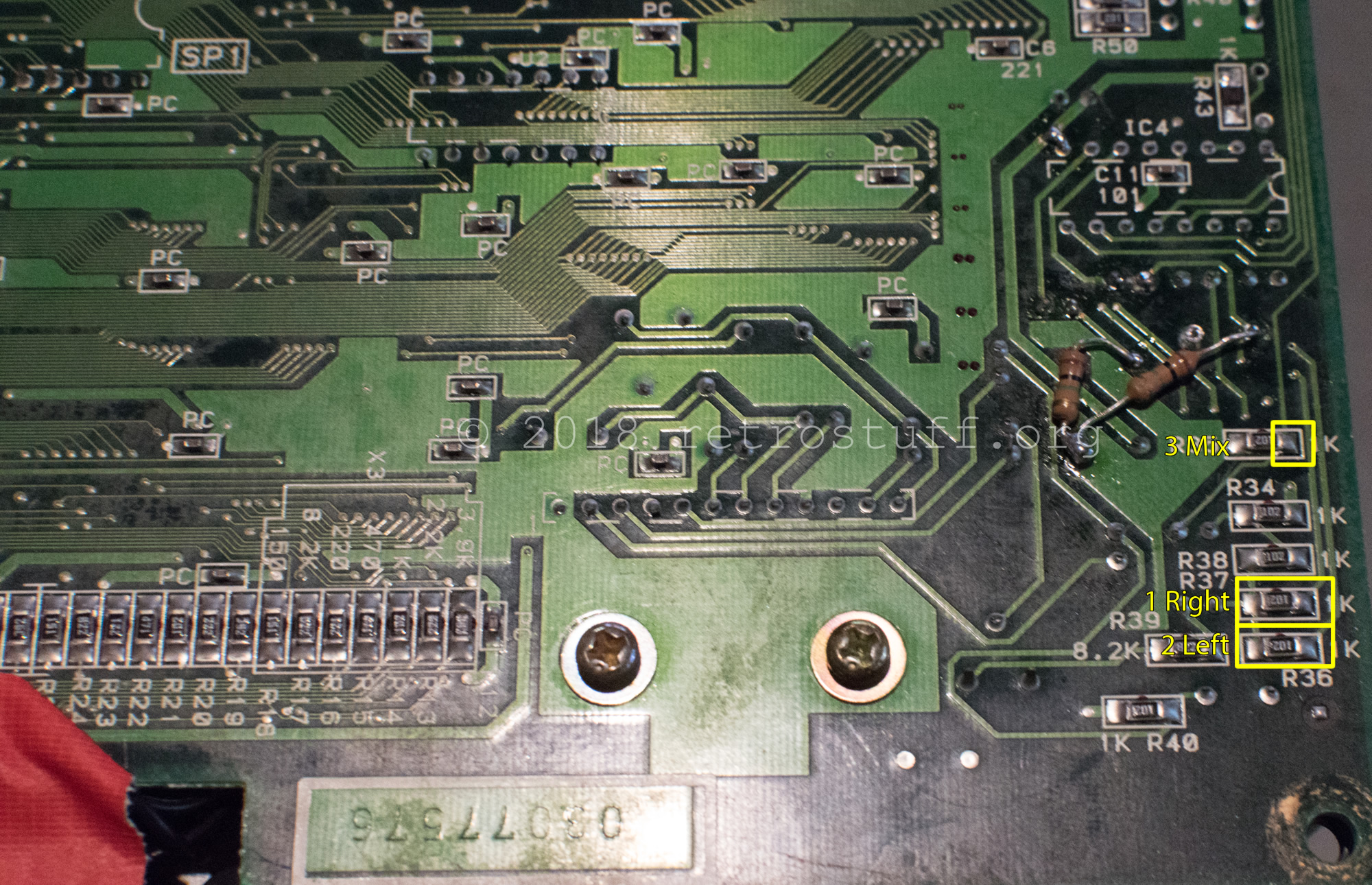
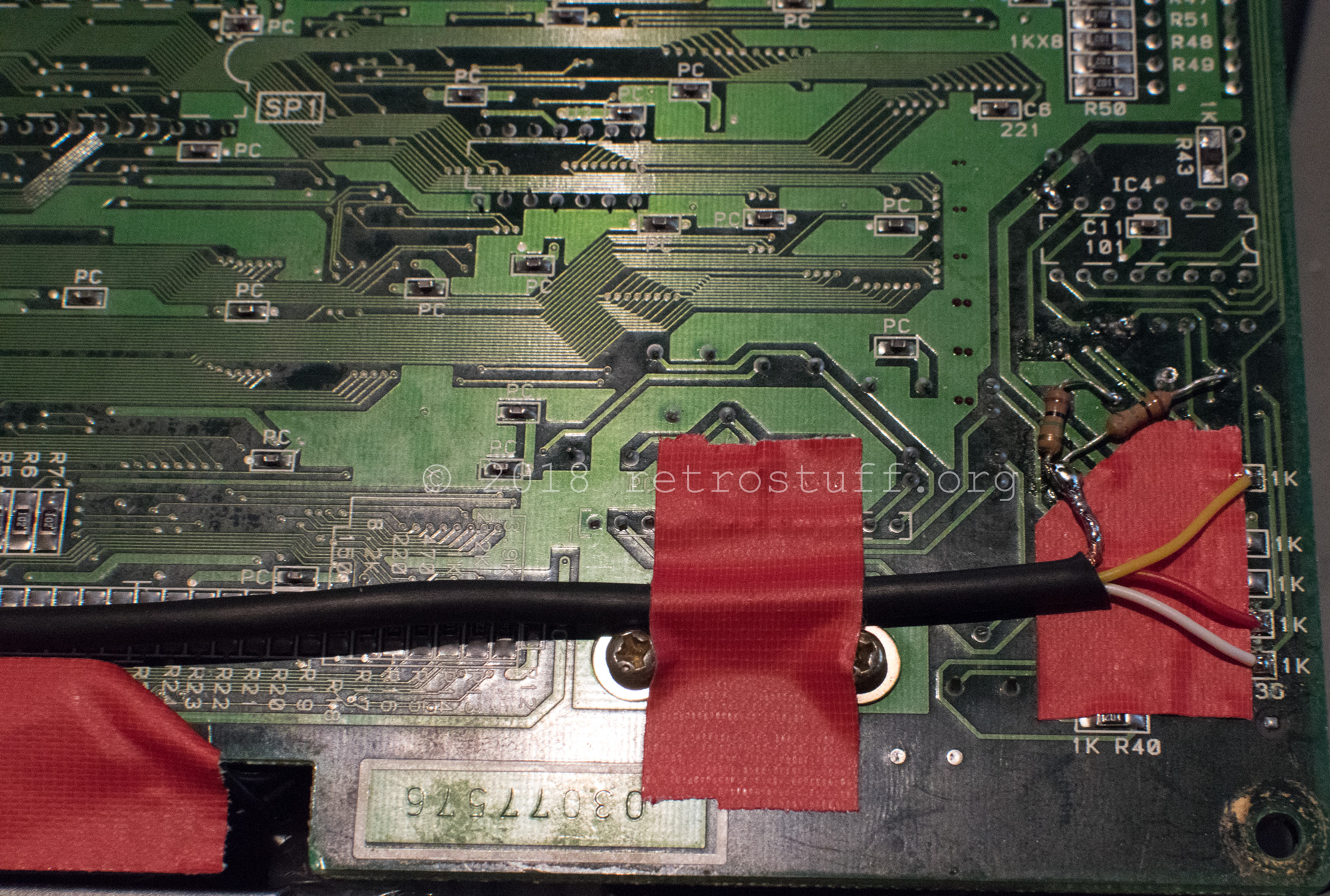
Once I was done, I was finally able to begin with the stereo modification. In order to achieve this, 3 audio signals needed to be tapped at the marked solder points, but first the connection between left and right audio channels needed to be broken by removing the two SMD resistors (1 and 2). Again, please read the tutorial ‘MV-1FZ Stereo Mod’ for details.
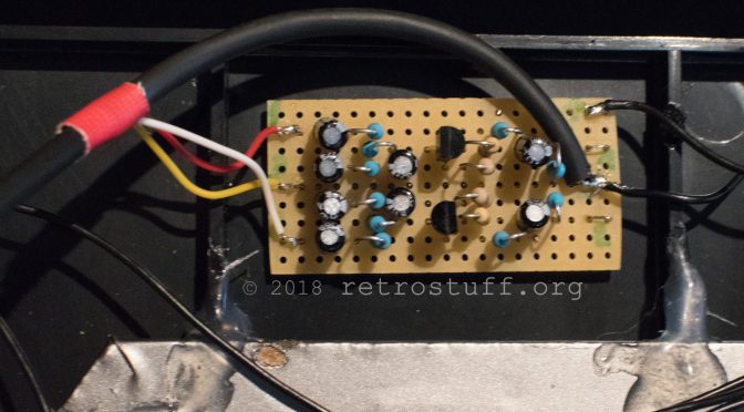
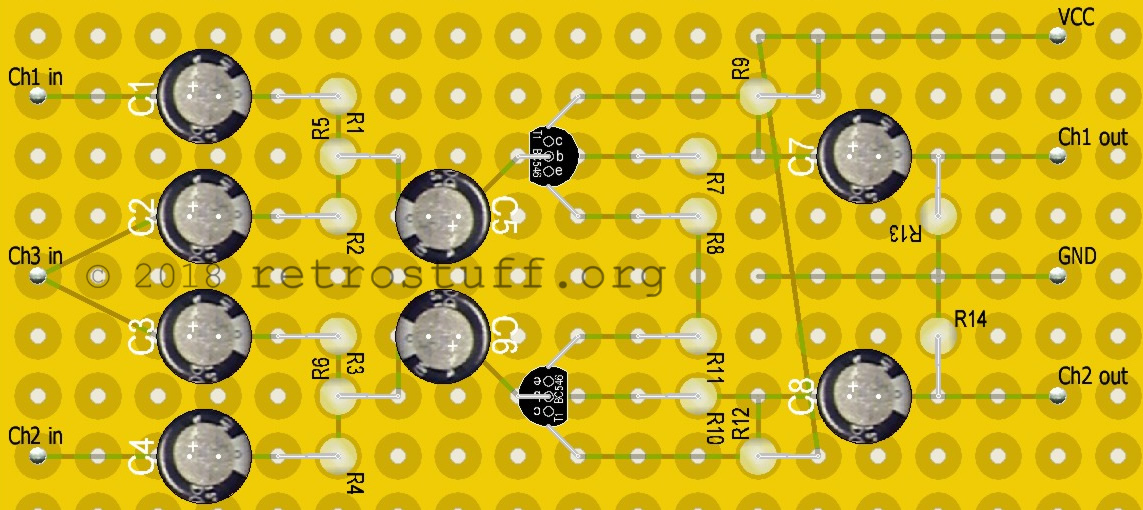
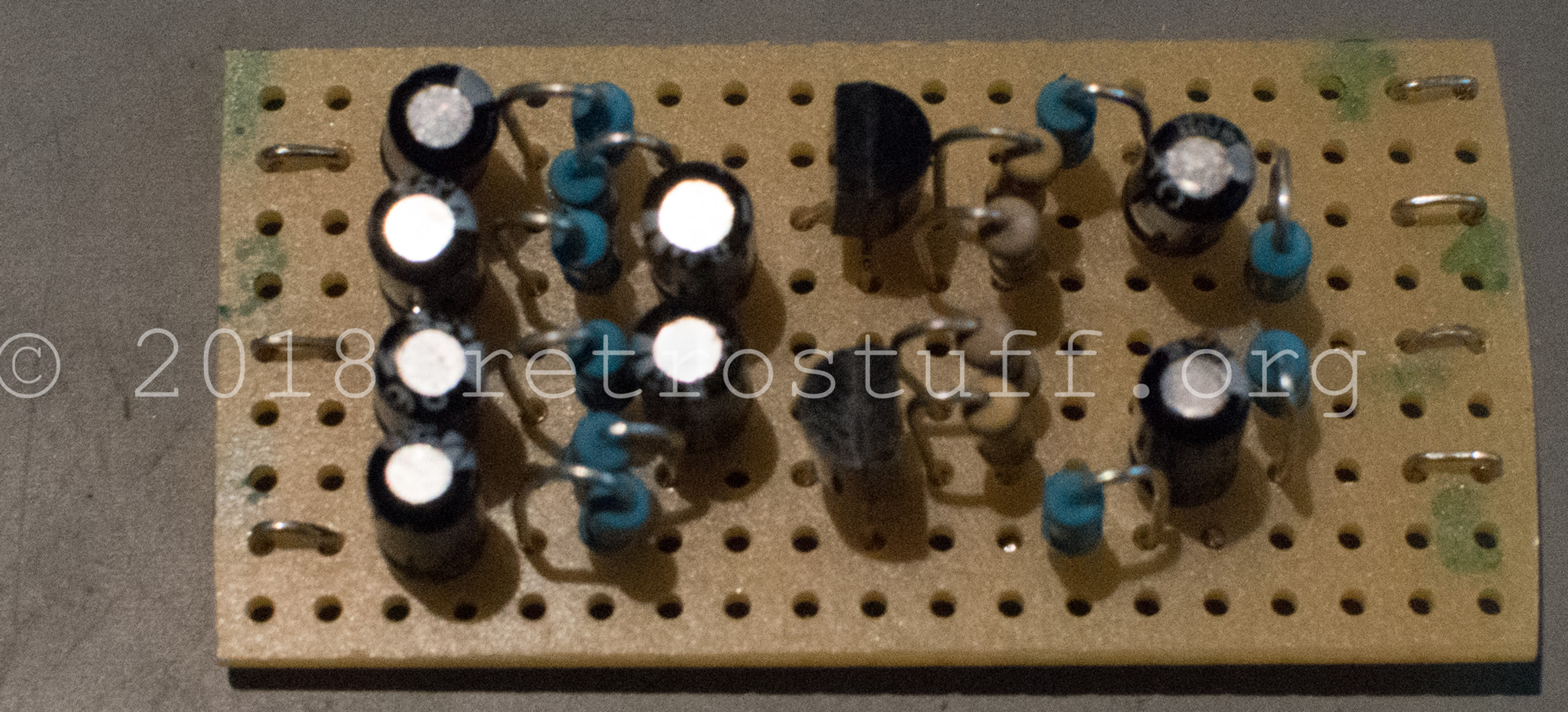
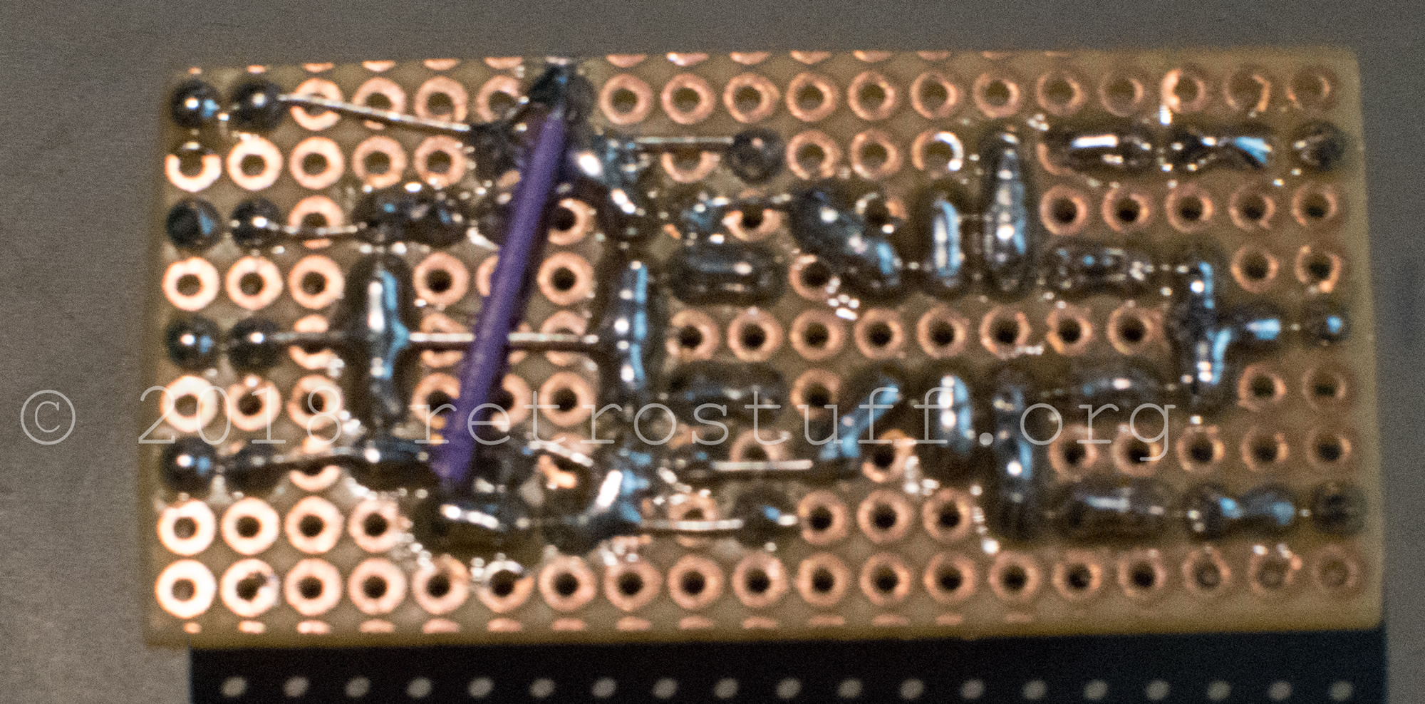
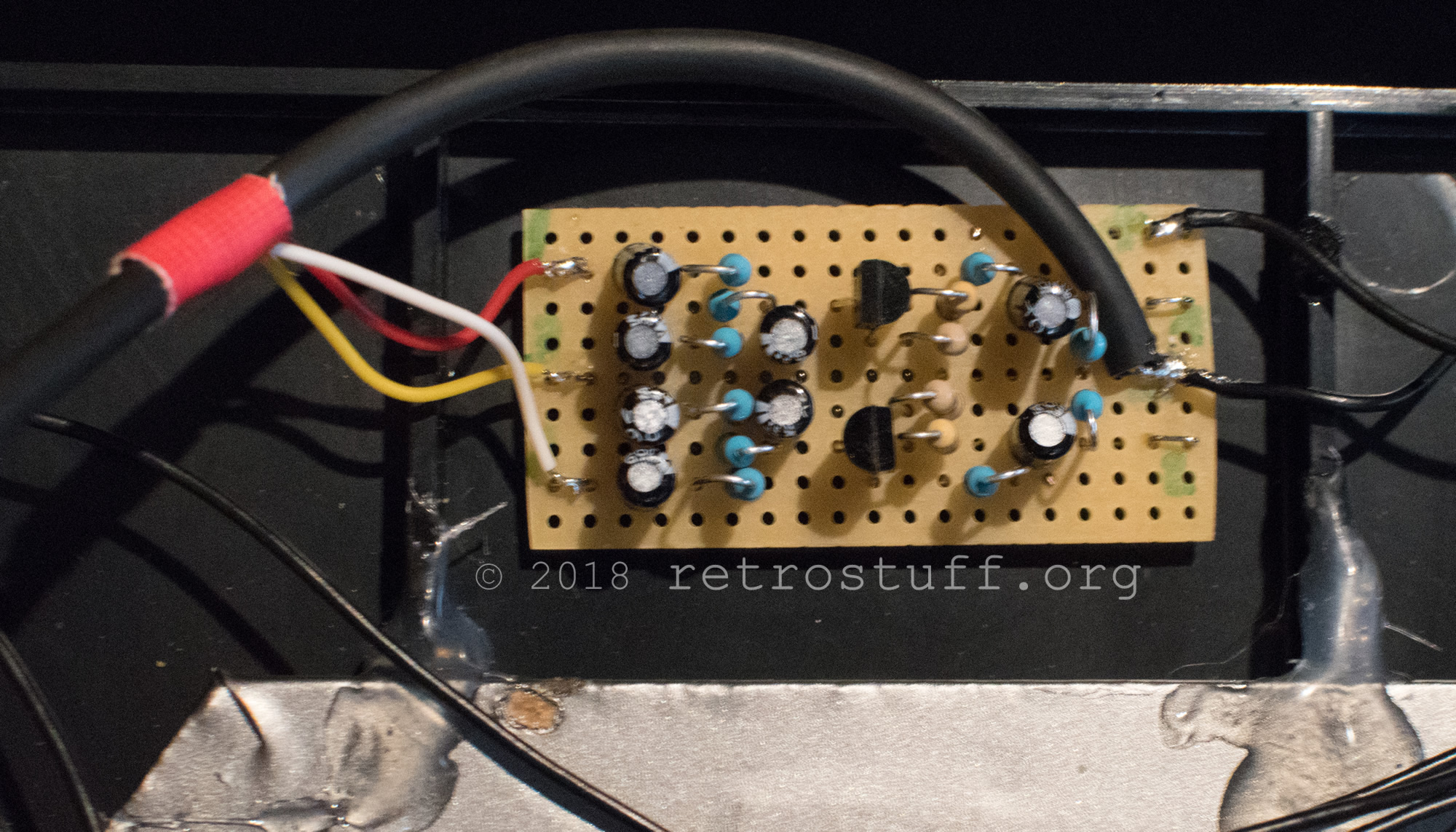
I went for the more sophisticated stereo splitter and amp by MKL. There is also a SMD variant, but I didn’t have the time to order and populate the PCB for it. Instead, I designed a perfboard for the components I had available. Pay attention to the NPN transistor, as I had to use a BC546 instead of a 2SC1815 and had to rotate it accordingly. I don’t like the 5V connection across the PCB, so if I ever have to do that again, I will probably rotate the transistors by 180° and have the VCC rail in the center of the PCB.

A shielded cable connects the 3 signals to the mixing PCB. I glued it in place where the DC-DC converter was before.
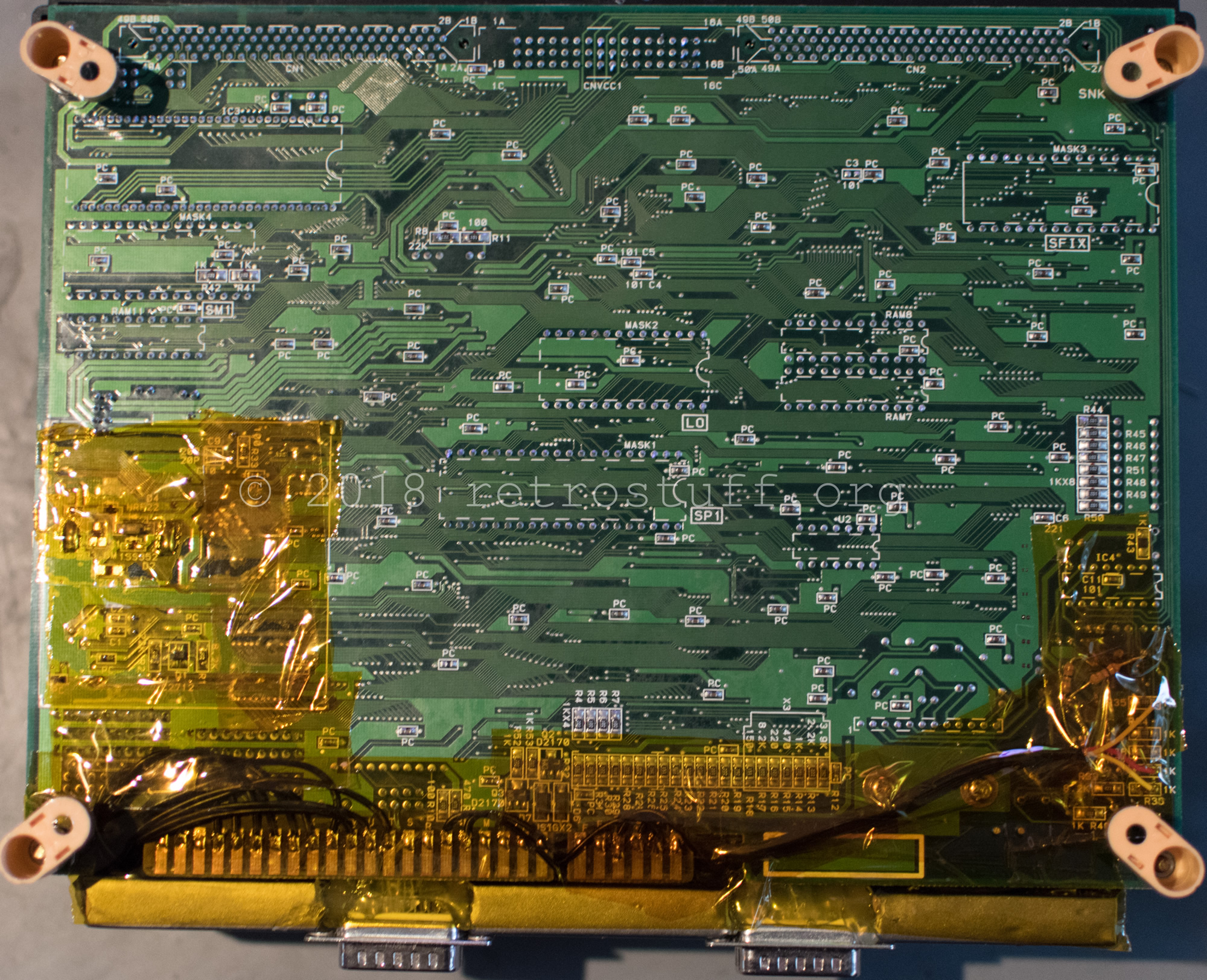
After I connected the separate audio channels to the SCART socket and play-tested it for a couple of hours, I finally removed the electrical tape and secured all sensitive areas with Kapton tape:
In the meantime, Universe BIOS v4.0 was released, so I took the opportunity to upgrade this board to the free version v3.3.